Physical Layer Network Coding for the -user Multiple Access Relay Channel
Abstract
A Physical layer Network Coding (PNC) scheme is proposed for the -user wireless Multiple Access Relay Channel (MARC), in which source nodes transmit their messages to the destination node with the help of a relay node The proposed PNC scheme involves two transmission phases: (i) Phase 1 during which the source nodes transmit, the relay node and the destination node receive and (ii) Phase 2 during which the source nodes and the relay node transmit, and the destination node receives. At the end of Phase 1, the relay node decodes the messages of the source nodes and during Phase 2 transmits a many-to-one function of the decoded messages. Wireless networks in which the relay node decodes, suffer from loss of diversity order if the decoder at the destination is not chosen properly. A novel decoder is proposed for the PNC scheme, which offers the maximum possible diversity order of for a proper choice of certain parameters and the network coding map. Specifically, the network coding map used at the relay is chosen to be a -dimensional Latin Hypercube, in order to ensure the maximum diversity order of Also, it is shown that the proposed decoder can be implemented by a fast decoding algorithm. Simulation results presented for the 3-user and 4-user MARC show that the proposed scheme offers a large gain over the existing scheme for the -user MARC.
I Background and Preliminaries
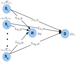
We consider the -user Multiple Access Relay Channel (MARC) shown in Fig. 1. Source nodes want to transmit messages to the destination node with the help of the relay node All the nodes are assumed to have half-duplex constraint, i.e., the nodes cannot transmit and receive simultaneously in the same frequency band. In a -user MARC, the maximum diversity order obtainable is two, since in addition to the presence of direct links, communication paths exist from the source nodes to the destination node through the relay node
I-A Background
In a fading scenario, Multiple Input Multiple Output (MIMO) antenna systems provide gain in terms of spatial diversity. However, in many practical scenarios, it is difficult to place multiple collocated antennas in a single terminal. An attractive alternative to obtain diversity gain without using multiple antennas, is the utilization of intermediate relay nodes which aid the transmission from the source nodes to the destination nodes. In order to exploit the presence of intermediate relay nodes to obtain diversity gain, the source nodes need to convey their messages to the relay nodes. Due to the superposition nature of the wireless channel, if the source nodes transmit simultaneously in the same frequency band, interference occurs at the relay nodes. A loss of spectral efficiency results, if the source nodes transmit in orthogonal time/frequency slots. A solution to this problem is the use of physical layer network coding, first introduced in [1], in which the nodes are allowed to transmit simultaneously. Physical layer Network Coding (PNC) has been shown to outperform traditional schemes which involve orthogonal transmissions [1]–[5]. So far, most of the works on PNC have mainly focussed only on the two-way relay channel. In our recent work [6], we proposed a scheme based on PNC for the two user MARC. In this paper, we present the generalization of the scheme proposed in [6] for the -user MARC.
For the MARC, a Complex Field Network Coding (CFNC) scheme was proposed in [7]. The CFNC scheme, like the PNC scheme, avoids the loss of spectral efficiency, by making the source nodes transmit simultaneously. But the major difference between the CFNC scheme and the proposed PNC scheme is that during the relaying phase, the CFNC scheme uses a signal set of size at whereas the proposed PNC scheme uses a signal set of size where is the size of the signal set used at the source nodes.
As noted in [7], if the relay node transmits a many-to-one function of the estimates of the messages transmitted by the source nodes and minimum squared Euclidean distance decoder is employed at D, a loss of diversity order results. This problem of loss of diversity order due to error propagation, is encountered in many other wireless scenarios as well and various solutions have been proposed to avoid this problem. Cyclic Redundancy Check bits are used so that the nodes forward only those packets which are decoded correctly [8]. Some works assume the knowledge of all the instantaneous fade coefficients or error probabilities associated with the intermediate nodes at the destination node, with the decoder at the destination using this knowledge to ensure full diversity [9],[10]. The CFNC scheme proposed in [7], uses a scaling factor at the relay node which depends on the instantaneous fade coefficients associated with the links from the source nodes to the relay node, with the scaling factor indicated to the destination using pilot symbols. The proposed scheme does not suffer from the disadvantages of any of the above methods, yet ensures the maximum possible diversity order. This is achieved by means of an efficient choice of the transmission scheme and the use of a novel decoder at the destination
For the proposed PNC scheme, making the source nodes also transmit during the relaying phase, combined with a novel decoder ensures the maximum possible diversity order of two. Furthermore, if certain parameters are chosen properly, the proposed decoder for the PNC scheme can be implemented with a decoding complexity order same as that of the CFNC scheme proposed in [7].
For the two-way relay channel, the network coding maps used at the relay node need to form a mathematical structure called Latin Squares, for ensuring unique decodability at the end nodes [11]. The structural properties of Latin Squares have been used to obtain the network coding maps in a two-way relay channel [11]–[13]. Interestingly, choosing the network coding map used at R to be a -dimensional Latin Hypercube, which is the generalization of the Latin Square to dimensions, helps towards achieving the maximum diversity order of two for the -user MARC.
The main advantages of the proposed scheme over the CFNC scheme proposed in [7] are summarized below:
-
•
In the CFNC scheme, transmits a complex linear combination of the estimate of the messages transmitted by the source node and the signal set used at during the relaying phase has points, where is the size of the signal set used at the source nodes. The minimum distance of the signal set used during the relaying phase vanishes as increases. In contrast, since the proposed PNC scheme uses a many-to-one map, the signal set used during the relaying phase has only points. The minimum distance of the signal set used at is more than that of the CFNC scheme and it remains the same irrespective of the number of source nodes Hence the proposed scheme performs better than the CFNC scheme. Simulation results presented for the 3-user and 4-user MARC confirm that the proposed PNC scheme provides a large gain over the CFNC scheme.
-
•
In the CFNC scheme, uses a scaling factor which is a function of the instantaneous fade coefficients associated with the links from the source nodes to the relay node, which needs to be indicated to using pilot symbols. Since the proposed PNC scheme does not involve any such scaling factor, there is no need of such pilot symbols.
Notations: Throughout, vectors are denoted by bold lower case letters and matrices are denoted by bold capital letters. The set of complex numbers is denoted by denotes a circularly symmetric complex Gaussian random variable with mean zero and variance and denotes a real Gaussian random variable with mean zero and variance For a matrix and denotes its transpose and conjugate transpose respectively. For a complex number denotes its conjugate and denotes its absolute value. For a vector denotes its Euclidean norm. The total transmission energy at a node is assumed to be equal to and all the additive noises are assumed to have a variance equal to By SNR, we denote the transmission energy For a signal set denotes the difference signal set of The all zero matrix of size is denoted by The natural logarithm of is denoted by denotes the expectation of denotes the complementary CDF of the standard Gaussian random variable.
I-B Signal Model
Throughout, a quasi-static fading scenario is assumed with the channel state information available only at the receivers. The source nodes want to transmit a binary vector of length to the destination node. At each one of the source nodes, the binary vector is mapped onto a point from a point signal set denoted by Let denote the mapping from bits to complex symbols used at the source nodes.
The proposed PNC scheme involves two transmission phases: Phase 1 during which the source nodes simultaneously transmit and, and receive, followed by the Phase 2 during which the source nodes and transmit to .
Phase 1
Let denote the complex symbol the source node wants to convey to During Phase 1, the source node transmits a scaled version of The received signal at and during Phase 1 are respectively given by,
| (1) |
where are constants and the additive noises and are assumed to be All the fade coefficients are Rayleigh distributed, with the fade coefficient associated with the - link and the fade coefficient associated with the - link
Based on the received complex number the relay node computes the Maximum Likelihood (ML) estimate of denoted by i.e.,
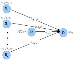
Phase 2
During Phase 2, the source node transmits a scaled version of and transmits where is a many-to-one function. The received signal at during Phase 2 is given by,
| (2) |
where are constants and the additive noise is assumed to be The fade coefficient associated with the - link is assumed to be
For the transmission energy at the source nodes to be equal to the constants and are chosen such that
From (1) and (2), the received complex numbers at during the two phases can be written in vector form as,
| (3) |
The matrix in (3) is referred to as the codeword matrix. The restriction of to the first rows, denoted by is referred to as the restricted codeword matrix, i.e., The difference between any two restricted codeword matrices is referred as the restricted codeword difference matrix, i.e., the restricted codeword difference matrices are of the form where
From (3), the vector can also be written as,
where is a matrix whose row is given by and all other entries are zeros. For the matrix the row is given by and all other entries are zeros. The matrices and are referred to as the weight matrices.
The contributions and organization of the paper are as follows: A novel decoder for the proposed PNC scheme is presented in Section II A. In Section II B, it is shown that the decoder presented in Section II A achieves the maximum diversity order of two if the following two conditions are satisfied: (i) the map used at the relay node forms a -dimensional Latin Hypercube and (ii) the constants and are such that every square submatrix of the restricted codeword difference matrices have rank two when takes non-zero values. In Section III, the condition under which the proposed decoder admits fast decoding is obtained. It is shown that when at least one of the weight matrices is Hurwitz-Radon orthogonal with the proposed decoder admits fast decoding, with the decoding complexity order same as that of the CFNC scheme proposed in [7]. Simulation results which show that the proposed PNC scheme provides large gain over the CFNC scheme are presented in Section IV.
II A Novel Decoder for the Proposed PNC Scheme and its Diversity Analysis
In the following subsection, a novel decoder for the proposed PNC scheme is presented.
II-A A Novel Decoder for the Proposed PNC Scheme
When uses the minimum squared Euclidean distance decoder given by,
a loss of diversity order results, since this decoder does not consider the possibility of decoding errors at the relay node.
Alternatively, we propose a novel decoder given by,
| (5) | ||||
| (6) | ||||
| (7) |
The idea behind the choice of this decoder is as follows: The optimal ML decoding metric at is equal to when the relay transmits the correct network-coded symbol. The relay transmits a wrong network-coded symbol, independent of if the joint ML estimate at the relay is such that Under this condition, the optimal ML decision metric at is given by At high SNR, the relay transmits a wrong network-coded symbol with a probability which is proportional to Hence, to the metric we add a correction factor of and the minimum of and is taken to be the decoding metric at .
The CFNC scheme proposed in [7] uses the minimum squared Euclidean distance decoder, which has a decoding complexity of Since the decoder given in (4) involves minimization over variables and it appears as though the decoding complexity order is In Section III, it is shown that by properly choosing the constants ’s and ’s, the decoding complexity order can be reduced to which is the same as that of the CFNC scheme.
II-B Diversity Analysis of the Proposed Decoder
The following theorem gives a sufficient condition under which the decoder given in (4) offers maximum diversity order two.
Theorem 1
For the proposed PNC scheme, the decoder given in (4) offers maximum diversity order two if the following two conditions are satisfied:
-
1.
The map satisfies the condition,
(8) for for all
-
2.
All submatrices of the restricted codeword difference matrices have rank two,
It is easy to verify that a map satisfying condition 1) above forms a Latin Hypercube of order and dimension
Definition 1
[14] A Latin Hypercube of order and dimension is an array of dimension with the indices for the dimensions as well as the entries filled in the array taking values from the symbol set Every symbol occurs exactly once along each one of the dimensions.
The dimension of the Latin Hypercube represents the transmission of the source node For simplicity, the points of the point signal set are indexed by integers from to The entries filled in the Latin Hypercube represent the transmission of the relay node.
| 0 | 1 | 2 | 3 | |
| 0 | 0 | 1 | 2 | 3 |
| 1 | 1 | 2 | 3 | 0 |
| 2 | 2 | 3 | 0 | 1 |
| 3 | 3 | 0 | 1 | 2 |
A Latin Hypercube of dimension 2 is a Latin Square. Fig. 2 shows an example of a Latin Square of order 4. It can be seen from Fig. 2 that no two entries repeat in a row as well as a column.
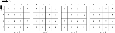
A Latin Hypercube of dimension 3 is a Latin Cube. The three dimensions of a Latin Cube are referred to as rows, columns and pages. Fig. 3 shows an example of a Latin Cube of order 4. It can be verified from Fig. 3 that in each one of the four pages, no two entries repeat in a row as well as a column. Similarly, for a fixed value of row index and a fixed value of column index, the entries in the four pages are distinct.

Fig. 4 shows a Latin Hypercube of dimension 4 and order 4. In Fig. 4 with a square for the which the indices of the third and fourth dimensions are fixed, no two entries repeat in a row as well as a column. Also, when the first three dimensions are fixed, no two entries repeat when the fourth dimension is varied. Similarly, fixing the first, second and fourth dimensions, the four entries obtained when the third dimension is varied are distinct.
For the 3-user MARC, the following example gives a choice of ’s and ’s for which Condition 2) given in Theorem 1 is satisfied.
Example 1
For the 3-user MARC, choosing and the restricted codeword difference matrices are of the form It can be verified that when and take non-zero values, the rank of every square submatrix of is two and hence condition 2) given in Theorem 1 is satisfied.
Example 2
For the 4-user MARC, choosing and the restricted codeword difference matrices are of the form It can be verified that when and take non-zero values, the rank of every square submatrix of is two and hence condition 2) given in Theorem 1 is satisfied.
In general, for the -user MARC, there are many possible ways of choosing ’s and ’s so that condition 2) given in Theorem 1 is satisfied. Choosing unit-norm vectors from such that for all ensures that condition 2) given in Theorem 1 is satisfied. One particular choice of ’s and ’s which satisfies the above condition for the -user MARC is given in the next example.
Example 3
Consider the set of vectors over given by
For the -user MARC, choosing and to be any distinct vectors from the set ensures that condition 2) given in Theorem 1 is satisfied.
III A Fast Decoding Algorithm for the Proposed Decoder
In this section, it is shown that if the constants ’s and ’s are chosen properly, the decoder given in (4) can be implemented using an efficient algorithm with a complexity order Note that for the CFNC scheme proposed in [7], the decoding complexity order at is
Before the algorithm is presented, some notations are introduced. The points in the signal set are denoted by
From (3), the vector can be written as,
The matrix can be decomposed using decomposition as where is a unitary matrix and is a matrix, with being upper-triangular of size and being a matrix. Let denote the entry of
Define Also, let
The following proposition gives a sufficient condition under which Algorithm 1 below implements the decoder given in (4).
Proposition 1
Algorithm 1111A algorithm exactly similar to Algorithm 1 can be used with the roles of and interchanged, if and are H-R orthogonal. implements the decoder in (4), if the constants ’s and ’s are such that the weight matrices and are Hurwitz-Radon (H-R) orthogonal, i.e.,
Proof:
The decoding metric of the decoder given in (4) can be written as,
In Algorithm 1, inside the nested for loops, the values of are fixed and the operations in lines 13, 14 and 15 involve a complexity order The operations from line 16 to line 23 involve constant complexity, independent of Hence the complexity order for executing the nested for loops from line 1 to line 29 is The operation in line 30 involves a complexity order Hence the overall complexity order of Algorithm 1 is which is the same as that of the CFNC scheme proposed in [7].
Example 4
Continuing with Example 1, for the 3-user MARC, when and and the weight matrices are given by, and It can be verified that the matrices and are H-R orthogonal, i.e., Hence, for this case, Algorithm 1 can be used to implement the decoder given in (4).
IV Simulation Results
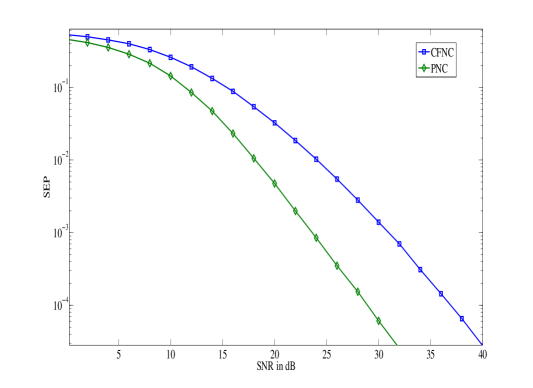
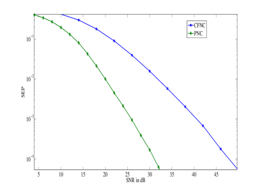
Simulation results presented in this section compare the performance of the proposed PNC scheme with the CFNC scheme proposed in [7], for the 3-user and 4-user MARC. In the simulation results presented for 3-user MARC, the values of the constants ’s and ’s are chosen to be the ones in Example 1 with 4-PSK signal set is used at the nodes and the Latin Cube given in Fig. 3 is used as the network coding map at the relay node. For the 4-user MARC, the values of the constants ’s and ’s are chosen to be the ones in Example 2 with 4-PSK signal set is used at the nodes and the Latin Hypercube of dimension 4 given in Fig. 4 is used as the network coding map at the relay node.
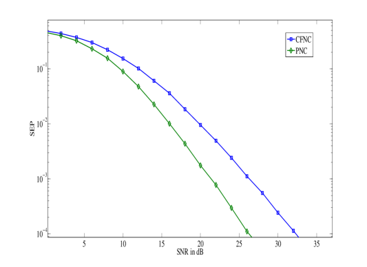
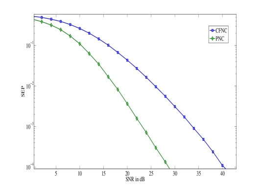
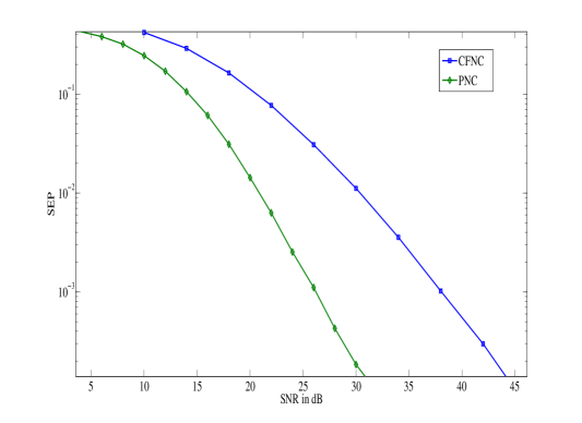
For the 3-user MARC, for the case when the variances of all the fading links are 0 dB, the SNR Vs. Symbol Error Probability (SEP) plots are shown in Fig. 5. It can be seen from Fig. 5 that the PNC scheme performs better than the CFNC scheme and offers a large gain of 8 dB, when the SEP is Fig. 6 shows a similar plot for the case when dB and dB, where It can be seen from Fig. 6 that for this case, the PNC scheme offers a gain of nearly 6 dB, when the SEP is Fig. 7 shows the plots for the case when the - link is stronger than all other links, i.e, and dB. For this case, the PNC scheme offers a large gain of about 12 dB, when the SEP is Also, it can be verified from the plots that the proposed decoder for the PNC scheme offers the maximum possible diversity order of two.
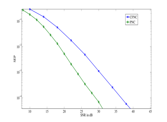
Fig. 8, Fig. 9 and Fig. 10 show similar plots for the 4-user MARC with 4-PSK signal set. When the variances of all the fading links are 0 dB, from Fig. 8, it can be seen that the proposed PNC scheme offers a gain of 13 dB, when the SEP is For the case when and all other variances are dB, from Fig. 9 it can be seen that the PNC scheme offers a gain of nearly 7.5 dB, when the SEP is For the case when the link from to is stronger the other links by 10 dB, it can be seen from Fig. 10 that the PNC scheme offers an advantage of 17 dB over the CFNC scheme.
V Discussion
A physical layer network coding scheme was proposed for the -user Multiple Access Relay Channel. For the proposed scheme, a novel decoder was presented and it was shown that the decoder offers the maximum possible diversity order of two if the network coding map used at the relay forms a -dimensional Latin Hypercube and every submatrix of a restricted codeword difference matrix has a rank two. Also, it was shown that the proposed decoder can be implemented using a fast decoding algorithm, if a weight matrix is Hurwitz-Radon orthogonal with for some The problem of finding the constants ’s and ’s which minimize the error probability in addition to ensuring maximum diversity order remains open. Extension of the proposed scheme for the case when there are multiple relay nodes is a possible direction for future work.
References
- [1] S. Zhang, S. C. Liew and P. P. Lam, “Hot topic: Physical-layer network coding,” in Proc. ACM Annual Int. Conf. Mobile Computing and Networking, Los Angeles, 2006, pp. 358–365.
- [2] P. Popovski and H. Yomo, “The anti–-packets can increase the achievable throughput of a wireless multi–hop network,” in Proc. IEEE Int. Conf. Communications, Istanbul, 2006, pp. 3885–3890.
- [3] P. Popovski and H. Yomo, “Physical network coding in two-Way wireless relay channels,” in Proc. IEEE Int. Conf. Communications, Glasgow, 2007, pp. 707–712.
- [4] M. P. Wilson, K. R. Narayanan, H. D. Pfister, and A. Sprintson, “Joint physical layer coding and network coding for bi-directional relaying,” IEEE Trans. Info. Theory, vol. 56, pp. 5641–-5654, Nov. 2010.
- [5] T. Koike-Akino, P. Popovski and V. Tarokh, “Optimized constellation for two-way wireless relaying with physical network coding,” IEEE J. Sel. Areas Commun., vol. 27, pp. 773–787, June 2009.
- [6] Vijayvaradharaj T. Muralidharan and B. Sundar Rajan, “Physical Layer Network Coding for the Multiple Access Relay Channel,” available online at arXiv: 1210.0490 [cs.IT], Oct. 2012.
- [7] T. Wang and G. B. Giannakis, “Complex field network coding for multiuser cooperative communications,” IEEE J. Sel. Areas Commun., vol. 26, pp. 561–571, April 2008.
- [8] M. Janani, A. Hedayat, T. Hunter, and A. Nosratinia, “Coded cooperation in wireless communications: space-time transmission and iterative decoding,” IEEE Trans. Signal Process., vol. 52, pp. 362-–371, Feb. 2004.
- [9] T. Wang, A. Cano, G. B. Giannakis and J. N. Laneman, “High-performance cooperative demodulation with Decode-and-Forward relays,” IEEE Trans. Commun., vol. 5, pp.1427–1438, July 2007.
- [10] M. Ju and I.- M. Kim, “ML performance analysis of the Decode-and-Forward protocol in cooperative diversity networks,” IEEE Trans. Wireless Commun., vol. 8, pp. 3855–3867, July 2009.
- [11] V. Namboodiri, V. T. Muralidharan and B. S. Rajan, “Wireless bidirectional relaying and Latin Squares,” in Proc. IEEE Wireless Communications and Networking Conf., Paris, 2012, pp. 1404–1409 (a detailed version is available in arXiv: 1110.0084v2 [cs.IT], 16 Nov. 2011).
- [12] V. T. Muralidharan and B. S. Rajan, “Wireless network coding for MIMO two-way relaying using Latin Rectangles,” in Proc. IEEE Int. Symp. Inf. Theory, Cambridge, 2012.
- [13] V. Namboodiri and B. S. Rajan, “Wirless network coding for QAM bidirectional relaying and Latin Squares,” in Proc. IEEE Global Telecommunications Conference, Anaheim, 2012.
- [14] K. Kishen, “On Latin and Hyper-Graeco-Latin Cubes and Hyper Cubes,” Current Science, vol. 11, pp. 98-–99, 1942.
- [15] K. P. Srinath and B. S. Rajan, “Low ML Decoding Complexity, Large Coding Gain, Full Rate, Full-Diversity STBCs for 2 2 and 4 2 MIMO systems,” IEEE J. Sel. Topics Signal Process., vol. 3, pp. 916–927, December 2009.
- [16] V. Tarokh, N. Seshadri and A. R. Calderbank, “Space–-time codes for high data rate wireless communication: Performance criterion and code construction,” IEEE Trans. Info. Theory, vol. 44, pp. 744–765, March 1998.
APPENDIX - Proof of Theorem 1
Let denote a particular realization of the fade coefficients. Throughout the proof, the subscript in a probability expression indicates conditioning on the fade coefficients. For simplicity of notation, it is assumed that the variances of all the fading coefficients are one, but the result holds for other values as well.
Let denote an error event that the transmitted message -tuple is wrongly decoded at D.
The probability of conditioned on given in (12), can be upper bounded as in (13) (eqns. (12) and (13) are shown at the next page). and respectively denote the probabilities that transmits the correct and wrong network coded symbol during Phase 2, for a given Also, the probability and the probability in (12) respectively denote the probabilities of given that transmitted the correct and wrong network coded symbol for a given can be upper bounded as in (14), where denotes the probability that the network coded symbol transmitted by is and the probability is the probability of given that R transmits for a given Taking expectation of the terms in (14) w.r.t we get (15).
| (12) | ||||
| (13) | ||||
| (14) | ||||
| (15) |
The rest of the proof of Theorem 1 is presented in two parts as Lemma 1 and Lemma 2. In Lemma 1, it is shown that the probability has a diversity order two. Lemma 2 shows that the probability has a diversity order one. Since has a diversity order one, Lemma 1 and Lemma 2 together imply that has a diversity order two.
Lemma 1
When the two conditions in the statement of Therorem 1 are satisfied, the probability has a diversity order two.
Proof:
Recall that the decoder used at D given in (4) in Section II A, involves computation of the metrics and defined in (5) and (6). Under the condition that transmitted the correct network coding symbol, a decoding error occurs at only when or for some Hence, the probability can be upper bounded as in (16), which can be upper bounded using the union bound as in (17) (eqns. (16) and (17) are given at the next page).
| (16) | ||||
| (17) |
The probability is equal to the Pair-wise Error Probability (PEP) of a space time coded collocated MISO system, with the codeword difference matrices of the space time code used at the transmitter being of the form where and When for at least two values of these codeword difference matrices are of rank 2, other wise condition 1) given in the statement of Theorem 1) will be violated. When and the codeword difference matrices are full rank, otherwise condition 2) in the statement of Theorem 1 will be violated. Since the codeword difference matrices are full rank, the probability has a diversity order two [16].
| (18) |
| (19) | ||||
| (20) | ||||
| (21) | ||||
| (22) |
Let be a metric as defined in (18), given in the next page. The probability can be written in terms of the metrics and as in (19), which can be upper bounded as in (20) (eqns. (19) – (22) are given in the next page).
Let The probability can be written in terms of the additive noise and as given in (21).
Let Also, let and Then (21) can be simplified as in (22), where is distributed according to In terms of the function, the probability in (22) can be written as Note that depends on the fade coefficients. To complete the proof, it suffices to show that has a diversity order two.
The vector x can be written as,
| x | |||
Since is Hermitian, it is unitarily diagonalizable, i.e, where is unitary and is a diagonal matrix. Since has a maximum rank two, the number of non-zero diagonal entries of has to be less than or equal to two. Let and denote the two diagonal entries of which are possibly non-zero, with We have Let The vector has the same distribution as that of since is unitary.
Since the rank of is at least one, We consider the two cases where and
Case 1:
For this case, upper bounding by which is upper bounded by we have
| (23) |
Taking expectation w.r.t and from (23), we get, Hence has a diversity order two.
Case 2:
For this case Hence,
| (24) |
Let Taking expectation w.r.t from (24), we get,
In the rest of the proof, we show that the integrals and have diversity order two. Note that as a function of attains the minimum value when and the minimum value equals Since, is a decreasing function of we have, Hence, we have,
Since for small can be approximated as at high we have Since has a diversity order at least two.
Let The integral can be upper bounded as, Let As a function of is monotonically increasing for Also, for can be written in terms of as, We have, Since can be upper bounded in terms of as,
Upper bounding by can be shown to be upper bounded as which falls as Upper bounding by and using the transformation can be upper bounded as,
where the second inequality above follows from the facts that and for sufficiently large The last equality follows from the fact that where is the integral, Since, has a diversity order 2. This completes the proof of Lemma 1. ∎
Lemma 2
When the two conditions in the statement of Theorem 1 are satisfied, the probability has a diversity order one.
Proof:
| (25) |
Let denote the metric as defined in (25), given at the top of the next page. Under the condition that transmitted the wrong network coded symbol a decoding error occurs at only when or for some and Hence, the probability can be upper bounded as in (26) (eqns. (26) – (29) are shown at the top of the next page). Using the union bound, from (26), we get (27).
| (26) | ||||
| (27) |
Since the matrix has rank at least one for where and the probability has a diversity order at least one.
can be written in terms of the additive noise and as given in (28).
| (28) | ||||
| (29) | ||||
Let Also, let and Then (28) can be simplified as in (29), where is distributed according to Hence,
| (30) |
Taking expectation with respect to the fade coefficients in (30), can be upper bounded as,
| (31) |
The vector x can be written as,
| x | |||
Since is Hermitian, it is unitarily diagonalizable, i.e, where is unitary and is diagonal with and denoting the two possible non-zero diagonal entries, where Since the rank of is at least one, We have Let The vector has the same distribution as that of since is unitary. Hence, we have,
Since, is exponentially distributed,
At high SNR, can be approximated as has a diversity order at least one since Since the integral on the right hand side of (31) can be upper bounded as,
| (32) |
We consider the following two cases when and
Case 1:
For this case, from the integral in (32), we get,
which falls as at high SNR.
Case 2:
For this case,
| (33) |
The above inequality follows from the fact that for Let From (33), since the integral can be upper bounded as,
| (34) |
Since
Since and can be approximated as one at high substituting for and we get,
Since the above upper bound on falls as at high SNR, has a diversity order at least 1. This completes the proof of Lemma 2. ∎