Black-Box Verification for GUI Applications
Abstract
In black-box testing of GUI applications (a form of system testing), a dynamic analysis of the GUI application is used to infer a black-box model; the black-box model is then used to derive test cases for the test of the GUI application. In this paper, we propose to supplement the test with the verification of the black-box model. We present a method that can give a guarantee of the absence of faults, i.e., the correctness of all test cases of the black-box model. The black-model allows us to formulate a parametrized verification problem. As we will show, it also allows us to circumvent the static analysis of the GUI tool kit. We have implemented our approach; preliminary experiments indicate its practical potential.
1 Introduction and Overview
Many of today’s applications provide a GUI (Graphical User Interface) which allows a user to interact with the system. A GUI consists of a set of widgets, e.g., buttons and check boxes. A user interacts with the system by manipulating these widgets, e.g., clicking a button, or selecting a check box. Each user interaction triggers an event. An event is a message generated by the GUI toolkit. A GUI application responds to a message with the execution of an event handler (e.g., a Java method).
The GUI application must not be confused with the GUI toolkit. In the fashion of an operating system, the GUI toolkit (through a message loop) continuously listens for events and, each time an event is triggered, initiates the execution of the corresponding event handler.
Until now, the topic of GUI applications as a target of formal, static analysis-based verification has received little attention (see, however, [7, 12, 14] for initial attempts). It is generally agreed that a static analysis cannot adequately account for the GUI toolkit (even its source code was fully available, which is generally not the case). The GUI toolkit is, however, an integral part of a GUI application. Without accounting for the GUI toolkit, it already seems impossible to infer what event sequences are executable (an event sequence models a user interaction). Not every event sequence is executable; for example, an event may lead to closing a window and thus disable another event.
In contrast, testing of GUI applications (which is a form of system testing) has become a very active research topic; see e.g., [1, 15, 16, 17, 4, 21] and the references therein. Within the setting of black-box system testing, a dynamic analysis of the GUI application is used to infer a black-box model. Subsequently, the black-box model is used to derive the test cases.
In this paper, we base ourselves on the notion of the Event Flow Graph (EFG), which is the particular black-box model in the popular approach of [17]. The nodes in an EFG are events. Its edge translate the is-followed-by relation between events. The EFG represents a set of event sequences (the labelings of the paths in the graph).
The EFG can be inferred automatically. A so-called GUI Ripper systematically explores the space of possible executions of the GUI application and records the is-followed-by relation between events during those executions through the edges of the EFG. Note that the exploration can never be guaranteed to be exhaustive (this is inherent to the black-box setting; an event can be missed, for example). Thus, the EFG is not guaranteed to include every possible event sequence of the GUI application.
In this paper, we take the view where the actual test of a GUI application is separated from the construction of the EFG. I.e., the test refers to the previously inferred EFG. The EFG serves to prescribe a set of potential test cases; i.e., the EFG defines an upper bound on the set of event sequences to be checked. Continuing this view, the EFG defines a specific verification problem: does there exist an event sequence in the given EFG that, if run on the GUI application, leads to a faulty execution?111The problem formulation (as well as our use of the term completeness) reflects the perspective of testing, which is falsification rather than verification. However, we view the problem as a verification problem.
The test of the GUI application with test cases derived from the given EFG provides an incomplete solution for the verification problem (incomplete because at no point, no matter how many test cases are derived from the EFG, the absence of faults can be guaranteed). In this paper, we present a complete solution to the verification problem.
The motivation is to supplement testing. Testing is known to be indispensable but it comes with the notorious deficiency of being incomplete. At some point during the test-debug cycle, the tester may desire a formal guarantee of the absence of faulty event sequences (in the set prescribed by the given EFG). Given such a guarantee, the tester can stop testing: no test case derived from the given EFG will yield to a positive.
As usual with an undecidable verification problem, the terminology complete solution refers to an abstraction-based verification algorithm with or without iterated abstraction refinement, i.e., with the possibility of non-termination or with the possibility of a don’t know answer.
From the perspective of the programmer, a GUI application consists of the family of event handlers but, as explained above, verification needs to also account for the effect of the GUI toolkit on the executability of event sequences. Thus, a static analysis-based verification method seems a no-go. However, and this is a basic observation put forward in this paper, at least some of the information about the effect of the GUI toolkit on the executability of event sequences is encoded in the EFG (simply by the fact that the EFG has been constructed by executing the GUI application).
In this paper, we propose a way to make this information available. Moreover, we can formally show that it is sufficient to solve our verification problem.
Given the EFG and the family of event handlers, one can construct a program that contains the event handlers and a mock-up of the GUI toolkit (of its message loop). The program mimicks the behavior of the GUI application as far it is represented by the EFG. We can show that by applying a static analysis-based verification method to the program, we obtain a complete solution for the verification problem for the GUI application and the given EFG.
We will next discuss another issue, an issue that leads us to enhancing the above verification method. That is, not every event sequence in the set represented by the EFG needs to be executable on the GUI application. This is because, although an event may be executable after another one in one path, this may no longer hold in another path (for an example, see Section 2). Formalized in the framework of abstract interpretation [10], the construction of the EFG uses an abstraction of the (finite) set of executed paths by a graph which denotes a larger (infinite) set of paths.
The program that we have constructed as input for verification accounts for the behavior of (the message loop of) the GUI toolkit according to the EFG. I.e., not every execution of the program may be executable on the GUI application. As a consequence, if the verification of the program returns a counterexample (a faulty execution of the program), then this counterexample may not be executable on the GUI application. In our setting of abstraction-based verification, we thus have two notions of spuriousness. The first spuriousness is due to the abstraction used by the static analysis (the path may be infeasible because of data dependencies). The second spuriousness is due to the use of a graph (i.e., the EFG) as a representation of a set of paths (the path may be not executable because of the behavior of the GUI toolkit).
There is no way to detect the non-executability statically (other than by the static analysis of the GUI toolkit). In the dynamic setting of testing, however, the non-executability of an event sequence is detected by nature. Having introduced a first heresy (by formally verifying a program that is inferred from a black-box model), we may be as well introduce a second heresy and use dynamic analysis in an abstraction refinement iteration. I.e., if the verification of the program detects a counterexample (i.e., an execution of the program that violates the correctness condition) and if the dynamic analysis determines the non-executability of the counterexample by the GUI application, then, as we will shown, the program can be refined so that the counterexample is no longer a possible execution of the new program. We thus enhance the verification method with a program refinement iteration.
Even without the program refinement iteration, the verification of the program constructed from a given EFG provides a guarantee of the absence of faults: no test case derivable from the EFG can lead to a faulty execution of the GUI application. The enhanced verification method (with the program refinement iteration) satisfies also the no false positives requirement. I.e., if a counterexample is returned then it indeed corresponds to an (“executable”) faulty execution, and if the GUI application does not have a faulty execution, then the method will not return a counterexample. This means that we can use our method not only for verification but also for falsification, i.e., as an enhancement of testing (it may find errors that testing might not find).
We have implemented our overall approach and we have evaluated it on a number of existing benchmarks from GUI testing. Our preliminary experiments indicate a promising potential of our method as supplement and enhancement to testing.
2 Motivating Example
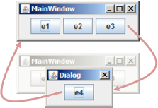
In this section we illustrate the application of our approach on an example of a GUI application. The example application depicted in the screenshot in Figure 1 consists of a MainWindow and a Dialog. The MainWindow contains three buttons that can fire the events , , and . The Dialog contains one button which can fire event .
In the first step of our approach we incorporate an Event Flow Graph (EFG) in order to model possible user interactions of the GUI application. An EFG is a directed graph where each node represents an event of the GUI. An edge between two events states that the corresponding events can be executed consecutively. The EFG of the example application depicted in Figure 2 consists of the four events , , , and . Such a graph represents the black-box model that is used to generate test cases in [17]. The idea is that a path in the EFG encodes a sequence of user interactions. The marking of , , and as initial nodes encodes how a user interaction can start. In our approach we automatically infer an EFG using reverse engineering [18]. Moreover, we apply our tool, called Gazoo [1], in order to extract the event handlers of each event.
The set of event handlers and the EFG serve as input for the translation of the GUI application into a verifiable program. That is, we apply our tool, called Joogie [2], in order to construct the program depicted in Figure 3 which represents the event handlers and a mock-up of the message loop as far it is represented by the EFG. The program starts with the block START which initializes the used variables. Furthermore, the block START provides a goto statement which allows the non-deterministic choice of the blocks e1, e2, and e3. The blocks that can be chosen within the block START conform to the initial events that can be chosen from the EFG. In this program, each event handler is encoded as a set of blocks. For example, the event is encoded in block e1, and event is encoded in the blocks e2, e2_THEN, e2_ELSE, and e2_ENDIF. The last block of each event handler contains a goto statement which allows a non-deterministic choice of possible succeeding events according to the EFG. The block EXIT contains a property, encoded as an assertion, which must hold after the execution of each event handler (the goto statement in each event handlers provides the possibility of choosing the block EXIT).
In the third step of our approach we apply a static analysis, called Kojak [13], on the program constructed in the previous step. We inject different assertions (that is, properties of the GUI application) and show the outcome of the static analysis.
If we inject the assertion assert(x != 7), the static analysis outputs the result UNSAFE, that is, a violation of this assertion is found in the program. In particular, the static analysis outputs the shortest sequence of events which leads to the violation, namely the event sequence .
In order to validate whether this event sequence is actually executable, we replay the event sequence on the GUI application using a replayer. That is, we apply the tool GUITAR [17], which takes as input a sequence of events to mimmick user interactions in a black-fashion on the GUI application. The result of the replayer states, whether the event sequence was successfully replayed or not.
In the case of the assertion assert(x != 7), the event sequence is not executable on the GUI. The reason is that the last event in the event sequence disables the event (which refers to line 17) in Figure 3. The fact that the event sequence is not executable causes our approach to automatically refine the used EFG.
The refinement step of our approach modifies the EFG, such that the detected non-executable event sequence (encoded as a path in the graph) is not contained in a refined EFG. In order to achieve this goal, we first convert both the EFG and the non-executable event sequence into automata, which allows us to apply operations from regular languages on these automata. In particular, the non-executable event sequence is encoded as an accepting word of the EFG automaton. We construct the complement of the accepting word and intersect it with the EFG automaton. The result is a refined EFG automaton which does not accept the non-executable event sequence. Finally, we convert the refined EFG automaton back into an EFG, which we call Extended EFG as depicted in Figure 4.
The extended EFG is now used to construct a new program. The static analysis is again applied to verify whether the assertion assert(x != 7) is violated. In this case, the output of the static analysis is SAFE, since there exist no sequence of events in the program which leads to the violation of the property.
For completeness we inject one further assertion: For the property assert(x != 3), the static analysis outputs the result UNSAFE and the event sequence which leads to the violating state. Unlike our first example, this event sequence is indeed executable on the GUI application without a further iteration of the refinement loop.
3 Approach
The runtime behavior of event-driven applications is determined by the occurrence of events. In our context, events can be triggered by the user interacting with the graphical user interface of the application. The GUI restricts the events that may be executed at any given time by, for example, enabling and disabling controls or displaying modal dialog boxes. An event flow graph effectively encodes those restrictions.
The goal of a tester is to determine whether, among the set of event sequences encoded by the event flow graph, all those that are executable in the application satisfy a property of interest. That is, whether they are correct. It is evident that testing cannot efficiently provide a guarantee that all test sequences are correct. We thus propose to encode the set of sequences represented by the EFG as a program, which traces correspond to event sequences of the EFG. The program can then be statically analyzed to efficiently determine whether all traces are correct, from which we can deduce that all sequences of the EFG are also correct. If a violating sequence is found, we use a replayer to dynamically check whether the sequence found is an executable one. In order to automate the process, a non-executable event sequence triggers a refinement loop where the EFG is modified to exclude all event sequences that start with the one found by the static analyzer.
The verification algorithm (see Algorithm 1) of our approach takes as input a system and an event flow graph . The system contains the GUI application to be tested (including the properties to be checked), the underlying GUI toolkit, the operating system, etc. The EFG can be created manually or automatically [18]. The algorithm starts with the extraction of the set of event handlers using the system and the EFG ; see line 2 and Section 3.1. Then, the algorithm constructs a program which represents a mock-up of the message loop by employing the set of event handlers and the EFG ; see line 4 and Section 3.2. In line 5, a static analysis is applied which returns a sequence of events ; see Section 3.3. If the event sequence is empty, then the static analysis did not find a violation of a property, and success is returned from the verification algorithm (line 14). In contrast, if the event sequence is not empty, then the static analysis found an event sequence which violates a property. Thus, the violating event sequence is replayed on the system ; see line 7, Section 3.4. The replayer returns a boolean flag indicating the executability of the sequence, and the non-executable prefix of the sequence . If was executable, the verification algorithm returns fail (line 11). If was not executable, the non-executable prefix of the event sequence is removed from the EFG; see line 9 and Section 3.5. The result of the refinement is an extended EFG, which is used to construct a new program .
We start by formalizing the problem of verification of GUI applications. We then describe the details of the steps involved in our proposed algorithm.
3.0.1 Extended Flow Graphs
In the literature [17], an event flow graph is defined as a directed graph where is the set of events, is the set of initial events and is the event flow relation. An edge between two events states that the event can be executed after the event . If there is no edge between events then event cannot be executed after event .
In order to support our refinement approach, we extend the classical definition of event flow graphs to enable having multiple nodes labeled with the same event.
Definition 1 (Extended Event Flow Graph)
An extended event flow graph is a labeled, directed graph where is the set of locations, the set of initial locations, the transition relation and a labeling function that assigns an event from the set of events to every location in .
We additionally define the set as the set of sequences of the form where , and .
An extended event flow graph (EEFG) thus encodes a set of event sequences that are considered possible in an application. That is, that the user interactions represented by the event sequence can be observed during the execution of the application.
Definition 2 (Possible Event Sequence)
Let be the set of all paths in the extended event flow graph . A sequence of events is called a possible event sequence if and only if there exists a path such that .
For brevity, we denote all possible event sequences for a given EEFG with the set .
3.0.2 Verification of GUI Applications
As usual, we define the states of an application as pairs where is the value of the program counter (the program location) and is a valuation function that assigns values to the program’s variables in their corresponding domains. There is a special state denoted by that is the state corresponding to the application’s entry point and the initial variable valuation.
An application trace is a sequence of states where and every , is the effect of executing the instruction at location under valuation . We assume the usual operational semantics of program instructions.
Some intermediate states in a trace correspond to the entry points of event handlers. Event handlers are program functions that are executed whenever an interaction with the graphical interface (an event) is triggered. We define the handler map function where is the set of events of the graphical interface and the set of locations that correspond to the entry points of the functions of the application.
For simplicity, and without loss of generality, we consider only events whose handlers change the program state without considering user inputs such as, e.g., scroll bars or text boxes. Those events that read user inputs can be replaced by a family of events where there is one for every possible input value. With that consideration we can construct the trace that corresponds to an event sequence.
Definition 3 (Traces from event sequences)
Let be an event sequence, the corresponding trace is
where the states are part of the initialization sequence of the application, states are the states at the entry point of the handler of event and the states are the states resulting from executing instruction of the event handler .
In our setting, assertions are special instructions of the form assert that have no effect on valuations and simply update the program counter to the following instruction. Arguments to assertions are boolean formulas over the application variables. A state satisfies the assertion at location if and only if and the interpretation of under valuation is (denoted ). We also introduce to denote the set of assertions in the code of application .
An event sequence is called correct if and only if every state in satisfies all assertions in the application’s code.
A GUI application, due to the restrictions imposed by its graphical interface, defines a set of event sequences that can be executed. We denote the set of executable event sequences of an application with . We thus redefine the notion of correctness.
Definition 4 (Application Correctness)
A GUI application is considered correct with respect to an EEFG if and only if all possible event sequences of the event flow graph that are executable, are correct. I.e.,
We thus aim to provide a guarantee of correctness with respect to an EEFG by applying the algorithm steps described in detail in the following sections.
3.1 Extracting Event Handlers
Each event in a GUI (e.g., a click on a button OK) is encoded as an event handler (e.g., OnClickOK). The step Event Handler Extraction mixes aspects of black-box and white-box approaches in order to extract the GUI’s event handlers. First, as in a black-box approach, we execute the GUI application and enumerate the GUI’s widgets (e.g., windows, buttons, and text fields). Then, leaving a pure black-box approach, we apply Reflection222http://java.sun.com/developer/technicalArticles/ALT/Reflection/ in order to obtain the Java object corresponding to each widget (e.g., JButton. We ask the Java object to invoke the method getActionListeners. The method invocation returns the widget’s event handlers (which are called action listeners in Java). In order to have a unique identifier for the event, we use the widget ID of the GUI application. If the Java object does not provide the method getActionListeners, there exists no registered event handler to this widget. In this case, we simply discard the handler event for this event. However, in the program construction the is-followed-by relation between events is considered.
3.1.1 Discussion
We use a dynamic approach to extract the event handlers. In principle it would be possible to extract these event handlers via a static approach by analyzing the source code. However, since GUI code is written in so many ways, looking for ActionListeners did not suffice as the event handlers might also be registered using callbacks, virtual function calls, or even external resource files.
3.2 Program Transformation
In order to encode the testing problem as a verification task, we construct a Boogie [3] program that incorporates the information of an EFG to simulate the message loop of the underlying GUI toolkit.
Given an EEFG , the program is constructed by first inlining all initialization functions to make sure the application’s variables have their initial values set correctly before simulating the message loop of the GUI toolkit. Subsequently, entry and exit labels for the message loop are added to the program. For each location in the EFG, the corresponding event handler is inlined. At the end of the block, a non deterministic goto statement is added. The target labels of the goto statement are the labels of the locations in the set . The jump to the exit label is necessary to simulate event sequences of finite length in the case of a cyclic EFG. Assertions in the application code are translated as assertions in .
To better illustrate the program transformation, the control flow graph of the program generated for the example in Section 2 is shown in Figure 5, a simplified version of the source code is shown in Figure 3. Note the similarity of the control flow graph of the generated program and the original EFG (see Figure 2).
Theorem 3.1
Let be an EEFG and be the set of traces feasible in the program . For every possible event sequence in , the corresponding application trace is feasible in the program . I.e.,
Proof
(sketch) For an arbitrary sequence , use Definition 3 to produce the corresponding trace . By the construction of , define a mapping from states of to states in the application. Also map instruction labels in the application correspond to instruction labels in .
Assuming , every subsequent application state is justified by an instruction in the application, show by the construction of that the mapped program state is justified by the corresponding instruction in . Split into cases for the initialization phase and the execution of event handlers.
Corollary 1
If a trace in violates an assertion (denoted , the corresponding event sequence calculated using the mappings from the previous proof and the inverse of Definition 3 is not correct.
In order to solve our problem of interest (see Definition 4), we apply static analysis to determine whether a trace that violates an assertion exists. By Corollary 1, the result of the analysis solves the problem
If a violating event sequence is found, it only remains to check whether it is executable.
3.2.1 Implementation
We implemented our translation approach for GUI applications written in Java, we integrate the generation of models as an option in Joogie [2], which translates Java bytecode into Boogie. Our implemented translation is available for download at joogie.org.
3.3 Static Analysis
In the following we will explain how static analysis processes the produced Boogie program to verify its safety wrt. assertions or to retrieve an event sequence . For our purposes we need a tool that can handle complex looping structures in programs well. In the case that the Boogie program has a feasible error trace, the tool should return the shortest trace that leads to the error, thus ensuring that the biggest possible trace sets are excluded from the EFG in every refinement step.
Additionally, the counterexample must be complete in the sense that it must document the error trace beginning from the initial location of the Boogie program to the failing assertion. We use the model checker Kojak (a loose homophone of “codecheck”) which is based on Ultimate [13]. Kojak uses a splitting algorithm with large block encoding(LBE) [6]. This combination has proven itself to be very efficient on programs with complex looping structures in program code. Kojak uses a breadth first search on the program. Therefore it always finds the shortest failing trace in the program. The interpolating splitting algorithm does not guess overapproximations of loops. It rather constructs an invariant for each loop. The invariant is constructed by splitting the loop using interpolation. A possible counterexample is encoded in a FOL formula and passed over to the interpolating theorem prover SMTInterpol [8]. If the formula is unsatisfiable the model checker obtains Craig interpolants for each node on the spurious counterexample and splits each node by partitioning its state space. On loops the splitting can be considered as an unwinding. Hence, due to the splitting, the counterexample is always complete in our sense and the corresponding trace is easy to comprehend from initial location to error location. As such Kojak fullfills all our requirements.
From Error Trace to Event Sequence.
The model checker Kojak constructs the control flow graph(CFG) of the Boogie program. As a preprocessing step the entire program is transformed into a simple goto-program. This eases the mapping of control locations in the code to the CFG. Each label becomes a node in the CFG. All other statements are encoded as transitions between those nodes. There exist 3 possible outcomes, (1) Safe, (2) Unsafe, and (3) Unknown (Figure 6).
| (1) Safe | Kojak has proved that the specified assertion is not violated in the program. Hence, there is no error trace to derive an event sequence from. |
|---|---|
| (2) Unsafe | Kojak has found a counterexample and its corresponding error trace. Kojak will derive the event sequence from the error trace and report that the assertion has been violated. The event sequence is returned as the witness of the error. |
| (3) Unknown | Kojak is neither able to verify the program nor to find a feasible counterexample. This can be caused e.g. by an unknown result from the theorem prover or a timeout etc. |
The result types (1) and (3) stop the computation and the overall algorithm. If the result is Unsafe, the event sequence must be derived from the error trace. The error trace is an alternating sequence of nodes and transitions. According to our prior explanation, each node corresponds to a label in the Boogie program. Specially marked labels of the Boogie program correspond to event handlers. Hence, we can easily derive the event sequence by mapping each marked label on the error trace back to its original event. This event sequence is handed over to the Replayer.
3.4 Replaying an Event Sequence
The replayer takes as input a sequence of events and embeds it into a GUI test case. A GUI test case consists of four components: (1) a precondition that must hold before executing an event sequence; (2) the event sequence to be executed; (3) possible input-data to the GUI; and (4) a postcondition that must hold after executing the event sequence. The step Replayer ensures the precondition, executes the event sequence on the GUI application, inserts input data where necessary, and checks if the postcondition holds. For (1), as a precondition we define that all user settings of an AUT have to be deleted before executing the event sequence. For (3), we generate random data, i.e., random strings for text boxes. The computation of suitable input values (see [14]) for widgets represents an orthogonal problem and is not in the scope of this paper. For (4), we use an executability monitor as an oracle, that is, the GUI test case is marked as passed if the event sequence is executable on the GUI application. The GUI test case is marked as failed if the event sequence is not executable on the GUI application. Furthermore, the replayer recognizes which event in the event sequence is not executable anymore. Then, the replayer stops the execution and extracts the shortest non-executable prefix of the event sequence. The replayer forwards the prefix (a sequence of events) to the refinement procedure, which removes the prefix from the used EFG.
3.5 EFG Refinement
An extended event flow graph can be seen as a finite representation of the regular language over the alphabet of events that contains possible event sequences of the program being analyzed (see Definition 2). We transform the extended event flow graph into a non-deterministic finite automaton (NFA) that accepts the regular language where:
-
•
The input alphabet is the set of events. I.e.,
-
•
For every location in there is a state in the NFA. I.e.,
-
•
An initial state is introduced.
-
•
All states except for the initial state are accepting states,
-
•
The transition relation is built from the transition relation of . Every edge in has a corresponding entry in the transition relation of . The successor event of the event flow relation is used as input symbol for the edge. Additionally, to account for multiple initial locations, an edge is introduced between the initial state and the states corresponding to those locations. I.e.,
Lemma 1
The language accepted by is exactly .
Proof
(sketch) Prove that any event sequence is accepted by . Apply induction over the prefixes of and the description of the construction of given .
A sequence of events returned as non-executable prefix of a violating sequence, is a word accepted by (see Section 3.2). If is a non-executable sequence, we exclude from the regular language of all sequences prefixed with , i.e., sequences of the form .
For that purpose, we construct an automaton that accepts exactly those sequences. By using the complement and intersection operations on finite automata, we obtain a new automaton that accepts exactly the language . The new automaton can be transformed back into an EEFG as follows:
-
•
There is a location for each state except for the initial state.
I.e., -
•
Every location is labeled with the input event of its incoming edges.333By construction, it is guaranteed that all incoming edges to a location are labeled with the same event. I.e., where is the input event of all incoming edges of , .
-
•
The initial locations are those connected to the initial state.
I.e., -
•
The transition relation is reconstructed from the transition relation of :
Lemma 2
is exactly the language accepted by .
Proof
(sketch) Analogous to Lemma 1. Prove that any sequence is accepted by by induction on the prefixes of and the construction of .
Having defined a translation of event flow graphs to and from NFA enables us to use the method to provide the refinement step of our algorithm (see line 9, Algorithm 1).
Theorem 3.2
The possible event sequences of the refined EEFG are the event sequences of the original EEFG without all sequences that start with . I.e., .
The refined event flow graph can thus be used for the subsequent iteration of our verification algorithm.
4 Evaluation
We apply our prototype implementation of the verification algorithm presented to some samples of the benchmark set UNL.Toy.2010 from the COMET benchmark repository444Available at comet.unl.edu. We modified each benchmark by adding a variable and assertions to the source code to specify the reachability of some value, analogous to our motivating example. For each sample we added an assertion that is never violated, and one where an executable event sequence leads to a violation.
The results of our experiments are summarized in Table 1. We report the number of events; the injected assertion; the time needed for the static analysis; the number of calls to the theorem prover; the number of refinement iterations (that is, the number of sequences that were replayed by our approach); the number of sequences of a pure black-box approach; and the final result of the benchmark.
In the case of an UNSAFE result of the static analysis, we compare the number of event sequences tested by our approach (the number of iterations) with the number of event sequences in a pure black-box approach that would be needed to guarantee correctness of the applications, that is, the detection of a violated assertion. Note, that in the case of a SAFE result of the static analysis, a pure black-box approach cannot guarantee the correctness of the application. Thus, we express the number of event sequences with .
| Benchmark | Events | Assertion | Time(secs) | TP Calls | Iterations | Sequences | Result |
|---|---|---|---|---|---|---|---|
| repair-2-cons | 3 | x!=8 | 1,802 | 267 | 2 | SAFE | |
| x!=9 | 0,216 | 33 | 1 | 9 | UNSAFE | ||
| repair-2-excl | 3 | x!=3 | 14,961 | 1482 | 4 | SAFE | |
| x!=4 | 0,066 | 33 | 1 | 9 | UNSAFE | ||
| repair-3-cons | 4 | x!=13 | 0,028 | 25 | 1 | SAFE | |
| x!=35 | 1,019 | 119 | 1 | 16 | UNSAFE | ||
| repair-3-excl | 5 | x!=13 | 0,021 | 36 | 1 | SAFE | |
| x!=25 | 0,505 | 116 | 1 | 25 | UNSAFE | ||
| repair-cmpd | 5 | x!=17 | 0,009 | 36 | 1 | SAFE | |
| x!=55 | 1,56 | 352 | 1 | 25 | UNSAFE |
5 Related Work
An approach which comes closest to our work is [19, 20] which incorporates planning from the domain of artificial intelligence to generate test cases for GUI applications. The input to the planning system is a set of operators (namely, the event handlers), an initial state, and a goal state of the application. The planning system outputs a sequence of operators that lead from the initial state to the goal state. However, in this approach a test engineer has to manually define the preconditions and effects of each operator. Our approach extends this idea as follows: First, we propose an automatic translation of the operators of a GUI application into a Boogie program. Second, the static analysis of our approach can be replaced by other techniques. Third, our approach replays an event sequence in a black-box fashion on the GUI application. Fourth, an event sequence which is not executable on the GUI is used to refine the model which is then again used to translate the GUI application.
The work in [5] presents a general approach to specify user interactions in GUI applications from a design perspective. This technique allows the analysis of user interactions using model checking, and the synthesis of user interactions to executable GUI applications. Since the work in [5] presents a high-level approach, it obviates the efforts of extracting models, e.g., from the source code of an existing application. In our case, we focus on supporting a test engineer which usually deals with executable GUI applications instead of abstract models. Hence, the translation of an existing application into a verifiable program presents one of the main technical contribution of this paper. In particular, our approach allows the analysis of an executable GUI application, e.g., even in the phase of release-to-manufacturing within a software release life cycle.
An approach which identifies useful abstractions of existing GUI applications is presented in [11]. Those abstractions are based on structural features of GUI applications, e.g., the enabledness of a button (enabled or disabled) using a boolean value, or the current value of slider control using an integer value. First, the abstractions are inferred manually from a GUI application. Then, the abstractions are used to build a model which is checked by SMV [9]. In order to overcome the manual identification abstractions, the work in [12] focuses on the automatic analysis of interaction orderings with model checking. In the work [12] the model is inferred via analyzing the code statically. The static analysis is tailored to a specific GUI toolkit, namely Java Swing. Our approach uses a dynamic approach: a model (the EFG) is created during the execution of the GUI application. Furthermore, our approach introduces a refinement loop which allows to improve the initial model by replaying event sequences obtained from the step static analysis. Since GUI code is written in many ways, a static analysis technique must be tailored to comprehend the behavior of each GUI toolkit. The use of a black-box model is justified by the reasonable trade-off between applicability and precision of a black-box model. Furthermore, the EFG is a black-box model which works independently from a currently used GUI toolkit.
The work in [1] (with shared co-authors) presents a lightweight static analysis, which generates all event sequences that are at the same time executable and justifiably relevant. First, the approach infers a model which expresses dependencies of events of the GUI application. Second, event sequences of bounded length are generated from this dependency model. Third, an event flow graph is incorporated in order to convert event sequences from the dependency model into executable event sequences. This paper represents a consistent further development: it uses an advanced static analysis which is able to reason about properties of a GUI application, instead of generating all event sequences that might violate a specific property.
6 Conclusion
In this paper, we have presented a method that can give a guarantee of the absence of faults, i.e., the correctness of all test cases of the black-box model of a GUI application. We have shown that the black-model allows us to circumvent the static analysis of the GUI tool kit, namely by constructing a program which is amenable to static analysis. We have implemented our approach and we have presented preliminary experiments which indicate its practical potential. The technical contribution of the paper is to make things work. This includes the construction of the program from a given EFG as input to a static analysis-based verification procedure and the program refinement procedure.
The main contribution of the paper is perhaps a conceptual one: the realization that formal, static analysis-based verification methods can have an interesting potential for GUI applications, namely as a supplement to GUI testing. The crux is to take the perspective of the GUI tester who, after having constructed the black-box model of the GUI application, is faced with what can be phrased as a verification problem.
In the future, we would like to explore efficient abstractions to support events with user inputs. In our implementation, an enhanced bytecode translation could increase the efficiency of static analysis by using a memory model optimized for the verification of GUI applications.
References
- [1] S. Arlt, A. Podelski, C. Bertolini, M. Schaef, I. Banerjee, and A. M. Memon. Lightweight Static Analysis for GUI Testing. In ISSRE. IEEE, 2012.
- [2] S. Arlt and M. Schaef. Joogie: Infeasible Code Detection for Java. In P. Madhusudan and S. A. Seshia, editors, CAV, volume 7358 of Lecture Notes in Computer Science, pages 767–773. Springer, 2012.
- [3] M. Barnett, B.-Y. E. Chang, R. DeLine, B. Jacobs, and K. R. M. Leino. Boogie: A Modular Reusable Verifier for Object-Oriented Programs. In F. S. de Boer, M. M. Bonsangue, S. Graf, and W. P. de Roever, editors, FMCO, volume 4111 of Lecture Notes in Computer Science, pages 364–387. Springer, 2005.
- [4] F. Belli. Finite-State Testing and Analysis of Graphical User Interfaces. In ISSRE, pages 34–43. IEEE Computer Society, 2001.
- [5] J. Berstel, S. Crespi-Reghizzi, G. Roussel, and P. S. Pietro. A Scalable Formal Method for Design and Automatic Checking of User Interfaces. In H. A. Müller, M. J. Harrold, and W. Schäfer, editors, ICSE, pages 453–462. IEEE Computer Society, 2001.
- [6] D. Beyer, A. Cimatti, A. Griggio, M. E. Keremoglu, and R. Sebastiani. Software model checking via large-block encoding. In FMCAD, pages 25–32. IEEE, 2009.
- [7] J. Chen. Formal Modelling of Java GUI Event Handling. In C. George and H. Miao, editors, ICFEM, volume 2495 of Lecture Notes in Computer Science, pages 359–370. Springer, 2002.
- [8] J. Christ, J. Hoenicke, and A. Nutz. SMTInterpol: An Interpolating SMT Solver. In SPIN, pages 248–254, 2012.
- [9] E. M. Clarke, O. Grumberg, and D. E. Long. Model Checking and Abstraction. In R. Sethi, editor, POPL, pages 342–354. ACM Press, 1992.
- [10] P. Cousot and R. Cousot. Abstract Interpretation: A Unified Lattice Model for Static Analysis of Programs by Construction or Approximation of Fixpoints. In R. M. Graham, M. A. Harrison, and R. Sethi, editors, POPL, pages 238–252. ACM, 1977.
- [11] M. B. Dwyer, V. Carr, and L. Hines. Model Checking Graphical User Interfaces Using Abstractions. In M. Jazayeri and H. Schauer, editors, ESEC / SIGSOFT FSE, volume 1301 of Lecture Notes in Computer Science, pages 244–261. Springer, 1997.
- [12] M. B. Dwyer, Robby, O. Tkachuk, and W. Visser. Analyzing Interaction Orderings with Model Checking. In ASE, pages 154–163. IEEE Computer Society, 2004.
- [13] E. Ermis, J. Hoenicke, and A. Podelski. Splitting via Interpolants. In V. Kuncak and A. Rybalchenko, editors, VMCAI, volume 7148 of Lecture Notes in Computer Science, pages 186–201. Springer, 2012.
- [14] S. R. Ganov, C. Killmar, S. Khurshid, and D. E. Perry. Event Listener Analysis and Symbolic Execution for Testing GUI Applications. In K. Breitman and A. Cavalcanti, editors, ICFEM, volume 5885 of Lecture Notes in Computer Science, pages 69–87. Springer, 2009.
- [15] F. Gross, G. Fraser, and A. Zeller. EXSYST: Search-based GUI testing. In ICSE, pages 1423–1426. IEEE, 2012.
- [16] L. Mariani, M. Pezzè, O. Riganelli, and M. Santoro. AutoBlackTest: Automatic Black-Box Testing of Interactive Applications. In G. Antoniol, A. Bertolino, and Y. Labiche, editors, ICST, pages 81–90. IEEE, 2012.
- [17] A. M. Memon. An event-flow model of GUI-based applications for testing. Softw. Test., Verif. Reliab., 17(3):137–157, 2007.
- [18] A. M. Memon, I. Banerjee, and A. Nagarajan. GUI Ripping: Reverse Engineering of Graphical User Interfaces for Testing. In A. van Deursen, E. Stroulia, and M.-A. D. Storey, editors, WCRE, pages 260–269. IEEE Computer Society, 2003.
- [19] A. M. Memon, M. E. Pollack, and M. L. Soffa. Using a Goal-Driven Approach to Generate Test Cases for GUIs. In B. W. Boehm, D. Garlan, and J. Kramer, editors, ICSE, pages 257–266. ACM, 1999.
- [20] A. M. Memon, M. E. Pollack, and M. L. Soffa. Hierarchical GUI Test Case Generation Using Automated Planning. IEEE Trans. Software Eng., 27(2):144–155, 2001.
- [21] L. J. White and H. Almezen. Generating Test Cases for GUI Responsibilities Using Complete Interaction Sequences. In ISSRE, pages 110–123. IEEE Computer Society, 2000.