Development of a SQUID-based 3He Co-magnetometer Readout for a Neutron Electric Dipole Moment Experiment
Abstract
A discovery of a permanent electric dipole moment (EDM) of the neutron would provide one of the most important low energy tests of the discrete symmetries beyond the Standard Model of particle physics. A new search of neutron EDM, to be conducted at the spallation neutron source (SNS) at ORNL, is designed to improve the present experimental limit of ecm by two orders of magnitude. The experiment is based on the magnetic-resonance technique in which polarized neutrons precess at the Larmor frequency when placed in a static magnetic field; a non-zero EDM would be evident as a difference in precession frequency when a strong external electric field is applied parallel vs. anti-parallel to the magnetic field. In addition to its role as neutron spin-analyzer via the spin-dependent n+3He nuclear capture reaction, polarized helium-3 (which has negligible EDM) will serve as co-magnetometer to correct for drifts in the magnetic field. In one of the two methods that will be built into the apparatus, the helium-3 precession signal is read out by SQUID-based gradiometers. We present a design study of a SQUID system suitable for the neutron EDM apparatus, and discuss using very long leads between the pickup loop and the SQUID.
Index Terms:
EDM, T violation, magnetic-resonance, 3He co-magnetometer, SQUIDI Introduction
The search for a permanent electric dipole moment (EDM) of elementary particles is an attempt to answer one of the most outstanding questions in the understanding of fundamental physics and the physics universe [1]. The existence of an EDM requires the violation of both the time-reversal (T) and the parity-inversion (P) symmetries due to their different transformation properties under discrete symmetry operations [2]. Hence, the EDM search provides direct information about the nature of T violation which is essential for explaining the observed baryon asymmetry of the universe. The Standard Model (SM) predicts a neutron EDM (nEDM) on the order of 10-31ecm [3], well below the current experimental limit of 10-26ecm [4], while many theories of physics beyond the SM lead to a sizable nEDM. The EDM search presents a powerful tool for tests of theoretical extensions to the SM [5].
In the attempt to improve the present experimental limit by two orders of magnitude, a new experimental search of nEDM, to be conducted at the spallation neutron source (SNS) at Oak Ridge National Laboratory, has been proposed [6]. In this paper, we describe the new nEDM experiment and focus on efforts to design a SQUID system into the nEDM cryostat for helium-3 magnetometer readout.
II Experimental Details
II-A Background
The technique to determine the nEDM, , is based on magnetic-resonance. Polarized neutrons precess at the Larmor frequency when placed in a static magnetic field, and a non-zero EDM would induce a shift in the precession frequency when the neutrons are subject to a strong external uniform electric field applied parallel or antiparallel to the magnetic field. The frequency shift due to an EDM is given by
| (1) |
where is the strength of the electric field applied along the magnetic field. Using the experimental goal precision of 10-28ecm as the size of the nEDM and an electric field of 50 kV/cm, the EDM-induced frequency shift is 2 nHz, equivalent to a precession frequency shift due to a change in the magnetic field of 0.1 fT. Thus, an EDM measurement to this level of precision requires extremely accurate monitoring of the magnetic field that the neutrons experience. Also required are a strong electric field, long observation times, and a large number of neutrons for statistical precision.
II-B Experimental Method
The experimental concept, due to Golub and Lamoreaux [7], employs ultracold neutrons (UCNs) — very low kinetic energy neutrons that can be confined to a material trap [8] — and 3He atoms dissolved in superfluid 4He. The 3He has a negligible EDM due to Schiff screening [9] of the nucleus and serves as a magnetometer over the same volume occupied by the UCNs, a so-called co-magnetometer. The 3He acts as neutron spin-analyzer via the spin-dependent nuclear capture reaction keV, which proceeds with a rate proportional to , where is the angle between the spin directions of the neutron and 3He. The triton and proton recoil products scintillate in the helium-4, and these flashes of light are detected.
To extract the nEDM signal, the apparatus will be capable of two different methods that we refer to as “dressed spin” and “free precession” modes. In the dressed spin mode, a relatively strong, high frequency alternating magnetic field (“dressing field”) is applied transverse to the static magnetic field . The parameters of the dressing field are chosen such that the neutron and 3He acquire the same effective gyromagnetic ratios. A modulation-feedback scheme, acting on the dressing field parameters and based on the observed capture reaction scintillation signal, measures the nEDM (see Ref. [7] for an extensive discussion of this technique).
The free precession mode is conceptually simpler and will be treated in the remainder of this paper: no dressing field is applied, and the UCNs and 3He are allowed to precess in a static magnetic field and parallel or anti-parallel electric field for a given measurement period, while scintillation events are recorded (3He as neutron spin-analyzer) and the 3He magnetization signal is directly detected (3He as magnetometer). The scintillation rate from neutron capture on 3He will be modulated as the polarization vectors of the neutron and 3He ensembles come into and out of alignment,
| (2) |
where and are polarization vectors, is the difference between the 3He () and neutron () precession frequencies, and is a constant phase. The 3He and neutron gyromagnetic ratios , differ by about 10%. Hence, in a static, uniform magnetic field, the scintillation event rate is modulated at about 10% of the 3He precession frequency. After correcting for any changes in the magnetic field, a difference in the scintillation modulation frequency, , when the electric field is reversed would indicate a non-zero nEDM signal. The nEDM, therefore, is extracted by the equation:
| (3) |
where the symbols () refer to the electric field parallel (antiparallel) to the magnetic field. The EDM sensitivity is estimated via error propagation to be
| (4) |
We note that the closeness of the gyromagnetic ratios of the two species relaxes the measurement precision requirement on by a factor of 10.
The 3He precession signal will be read out with SQUID gradiometers. An estimate of the resolution of the measurement, in the limit that transverse relaxation time is much longer than the measurement period, is [10]
| (5) |
where is the signal flux in the SQUID loop, is the flux noise spectral density in the SQUID at the signal frequency, and is the measurement period. Taking into account the expected statistical precision of the measurement, the goal of the co-magnetometer readout is Hz per 800 second measurement period, such that does not contribute significantly to the overall uncertainty of the experimental result.
II-C Experimental Parameters
The choice of operating conditions — cell temperature and geometry, magnetic field, 3He density, etc. — is driven by the statistics requirement of the neutron spin-analyzer events ( captures) that measure the beat frequency , and by known systematic errors that must be minimized. Here, we will describe the conditions, in which the co-magnetometer readout must operate, and leave further explanations to Refs. [6] and [7]. Two independent, identical, rectangular ( cm3) measurement cells are arranged symmetrically on either side of a high-voltage (500 MV) electrode with ground electrodes on the outboard sides of the cells, as shown in Fig. 1.
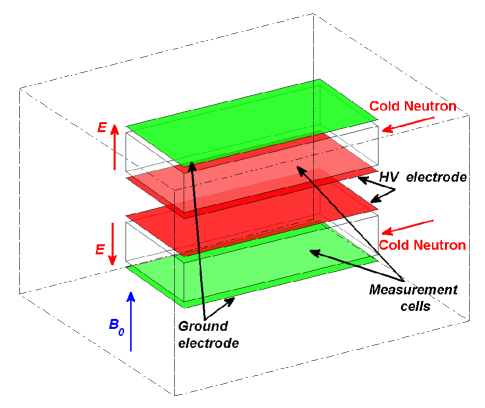
An applied, highly uniform magnetic field T is common to both cells; thus, the and fields are parallel in one measurement cell and antiparallel in the other. The cells are filled with isotopically purified helium-4 at nominal temperature mK (which may changed to as low as 300 mK for systematics studies) and contained in a 1000-liter, helium-4-filled G10/composite vessel cooled to the operating temperature by a dilution refrigerator. Approximately 100%-polarized 3He from an atomic beam source are filled into both cells to a number density /cm3. UCNs are produced in the cells in situ, starting with a cold neutron beam from the ORNL Spallation Neutron Source, by a phonon recoil process with the superfluid helium-4; up to 100 UCN/cc are expected.
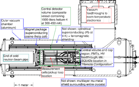
The infrastructure to create these experimental conditions and perform the measurement cycles is considerable. Research and development, and preliminary engineering, have led to the apparatus depicted in Fig. 2.
II-D Magnetic Field
Even with the co-magnetometer, control of the magnetic field environment is critically important. The holding field will be produced with an optimized cosine-theta magnet coil with superconducting windings cooled to 4 K. Surrounding the coil is a cylindrical ferromagnetic shield that improves the uniformity of the field over the measurement cells. Proceeding radially outward, next is a cylindrical superconducting shield (Pb at 4 K), then the aluminum vacuum vessel of the cryostat, and finally a multilayer high-permeability shield surrounding the entire cryostat.
Known systematic effects in this experiment are caused by magnetic field non-uniformities in the measurement cells. The “ false-EDM” effect, a frequency shift linear in that mimics an EDM, is caused by an interplay of motional fields (where is an individual particle velocity) with gradients in the static magnetic field [11]. This and other known systematic effects sets the magnetic field uniformity requirement of roughly fT/cm, where the brackets with subscript indicate volume averaging over the measurement cell. The amount and geometry of magnetic and superconducting materials near the cells must be restricted, since they could distort the field.
III Helium-3 Co-magnetometer Readout
In the free-precession version of the nEDM experiment, the 3He magnetization signal will be directly detected with superconducting gradiometers coupled to SQUIDs. With T, the signal frequency is approximately 100 Hz. Applying Eq. 5 with measurement time seconds and requiring Hz, we find the signal-to-noise ratio in the SQUID must satisfy . The available signal is quite small because of the very low helium-3 concentration. Furthermore, the pickup loops must be positioned behind the ground electrodes of each cell to avoid high-electric-field regions. The feasibility of SQUID detection of the 3He precession frequency in these conditions has been demonstrated (by extrapolation) with a simple setup [12]. However, the nEDM apparatus presents technical challenges to full implementation of a SQUID-based co-magnetometer readout, such as 1) the long distance (7 meters) between the measurement cells and room-temperature electronics, 2) limitations on shielding such as superconducting conduit near the measurement cells, 3) other devices (photomultiplier tubes, temperature sensors), which could potentially emit RF inteference, must operate during the measurement period.
III-A Pickup Loops
We propose a thin-film planar gradiometer as a pickup loop consisting of two series-configured 3 cm6 cm pickup loops with center-to-center spacing of 9 cm. The pickup loop is fabricated on a 150 mm Si wafer, and the inductance is estimated to be 540 nH. Eight individual gradiometers behind each ground plane and distributed across the cell face, with a nominal distance of 3 cm between the nearest part of the gradiometer and the inside of the cell, are considered.
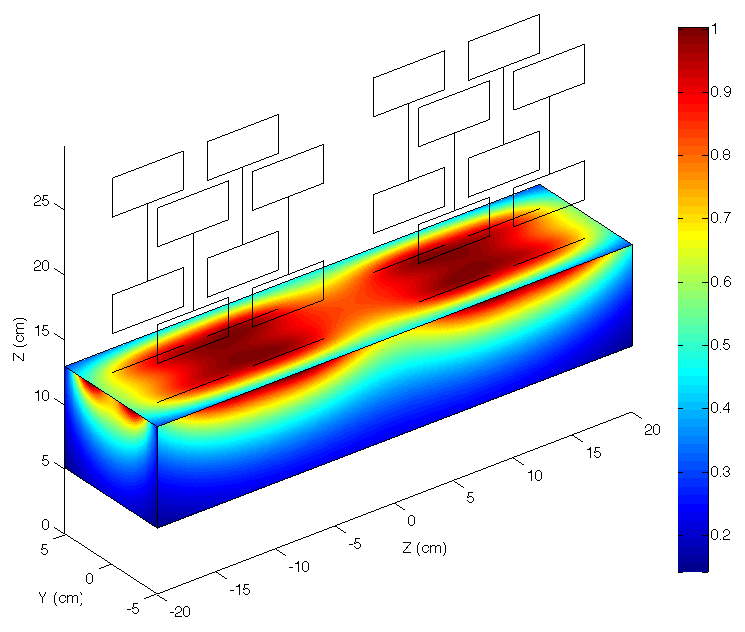
We calculate the signal flux amplitude through the array of eight gradiometers for one EDM cell with 3He concentration atoms/cm3. The magnetic flux through each pickup loop due to a 3He dipole aligned with the -axis and located at is computed. Then, numerical integration of over the cell volume, appropriately scaled with the helium-3 number density, gives the total flux expected in the pickup loops. The average flux through each pickup (total through the gradiometer array divided by number of pickups) is calculated to be 2000 , where is the magnetic flux quantum; dividing by the half-gradiometer area 18 cm2 gives an equivalent average signal amplitude of 2.3 fT. The relative sensitivity of the gradiometer array to voxel position is shown in Fig. 3. We see that the coverage is good across the ground-side face of the cell but falls off fairly quickly for sources deeper in the cell. However, because of the large diffusion constant of dilute 3He in 4He at the measurement temperatures (400 cm2/s at 0.45 K [13]), each spin traverses the cell many times during the measurement period, and thereby samples the whole cell volume.
III-B SQUID Configuration
The signal in the pickup loop must be coupled into a SQUID for detection. The flux in the SQUID is related to the flux in the pickup by
| (6) |
where is the SQUID input loop coupling, is the SQUID input loop inductance, is the pickup loop inductance, and is parasitic inductance in the leads connecting the pickup loop to the SQUID input loop.
We consider two SQUID configurations with the gradiometer pickup loops. One we term the “Piggybacked SQUID,” in which the SQUID mounted atop the gradiometer pickup and connected with very short leads. The other is the “Remote SQUID” configuration in which the SQUID is mounted outside the Central Volume and connected with long (3.5 m) superconducting twisted-pair leads.
The advantage of the Piggybacked SQUID configuration is to maximize the possible signal-to-noise ratio (SNR) by minimizing parasitic inductance. On the other hand, more wires (six or eight per SQUID) to control the SQUID outside the nEDM cryostat must be inside the Central Detector volume; it would be much more difficult to replace the SQUID if damaged because the Central Detector volume would have to be opened; and heating the SQUID to expel trapped flux may be difficult (though perhaps possible with suitable insulation) since it is immersed in the 1000-liter superfluid helium-4 bath.
In the case of the Remote SQUID configuration, there are more advantages in spite of the reduction of SNR due to the large parasitic inductance of the twisted-pair leads (we measured 2.3 nH/cm for 3-mil Nb wires): (a) only two wires per SQUID would be in the Central volume; (b) minimal superconducting material near the measurement cells; (c) replacement of SQUIDs is easier; (d) the SQUID itself can be housed in a superconducting enclosure. We are presently pursuing this configuration because of these advantages and indications that the SNR will be sufficient.
For the Remote SQUID configuration, a high-inductance SQUID (StarCryo SQ2600, with of 2585 nH and of 21 nH) has been chosen to increase the SNR because the parasitic inductance is relatively less important. We measured the intrinsic noise in the SQUID sensor with a dummy load of 2600 nH to be 3.4 at 1 kHz and 4 Kelvin. Furthermore, we tested the flux noise with a 3.5 m niobium twisted-pair lead connected to the input coil. The far end of the leads was shorted. We confirmed that the noise is roughly the same as with the above, which means long leads do not degrade the SQUID’s performance. We find the optimal number of pickup loop turns by scaling the signal flux by and the pickup loop inductance by in Eq. 6, with nH for the 3.5 m leads. Two or three turns give the same, optimal SNR of , satisfying the nEDM requirement. Owing to eight gradiometers, the SNR may be further increased by a factor of . In addition, the SQUID intrinsic noise may be improved at the operating temperature, , much lower than 4.2 K as much as a factor of [14].
IV Future Work
We plan to study experimentally the Remote SQUID configuration with shielding and magnetic fields similar to the planned nEDM apparatus. Furthermore, we will test the compatibility of low-noise SQUID operation with other devices that are potential sources of electromagnetic interference, especially photomultiplier tubes, which are necessarily operating during the measurement period.
V CONCLUSION
A new search for nEDM aiming to 100-fold improvement in the present experimental limit is described. This experiment employs polarized helium-3 as neutron spin-analyzer and co-magnetometer. In one operating mode of the experiment, the 3He co-magnetometer is read out by first-order planar gradiometers. A configuration in which the gradiometer pickup loop is attached to the SQUID by very long leads appears feasible and offers some advantages over a piggybacked configuration.
Acknowledgment
We thank Robin Cantor, Michelle Espy and Andrei V. Matlashov for assistance with SQUID system tests as well as very helpful discussions. This work was supported by the US DOE Office of Science, Nuclear Physics.
References
- [1] E. M. Purcell and N. F. Ramsey, “On the possibility of electric dipole moments for elementary particles and nuclei,” Physical Review, vol. 78, p. 807, 1950.
- [2] L. Landau, “On the conservation laws for weak interactions,” vol. 3, p. 127, 1957.
- [3] I. B. Khriplovich and S. K. Lamoreaux, CP-Violation Without Strangeness. Springer, 1997, pp. 113–114.
- [4] C. A. Baker et al., “Improved experimental limit on the electric dipole moment of the neutron,” Physical Review Letters, vol. 97, p. 131801, 2006.
- [5] V. Cirigliano, Y. Li, S. Profumo, and M. J. Ramsey-Musolf, “MSSM baryogenesis and electric dipole moments: an update on the phenomenology,” Journal of High Energy Physics, vol. 2010, p. 1, 2010.
- [6] Neutron EDM Collaboration, “A new search for the neutron electric dipole moment,” Los Alamos National Laboratory, Tech. Rep. LA-UR 02-2331, 2002, http://p25ext.lanl.gov/edm/pdf.unprotected/EDM_proposal.pdf.
- [7] R. Golub and S. K. Lamoreaux, “Neutron electric dipole moment, ultracold neutrons, and polarized 3He,” Physics Reports, vol. 237, 1994.
- [8] R. Golub, D. J. Richardson, and S. K. Lamoreaux, Ultracold Neutrons. Adam-Hilger, Bristol, 1991.
- [9] L. I. Schiff, “Measureability of nuclear electric dipole moments,” Physical Review, vol. 132, p. 2194, 1963.
- [10] Y. Chibane, S. K. Lamoreaux, J. M. Pendlebury, and K. F. Smith, “Minimun variance of frequency estimations for a sinusoidal signal with low noise,” Measurement Science Technology, vol. 6, p. 671, 1995.
- [11] A. L. Barabanov, R. Golub, and S. K. Lamoreaux, “Electric dipole moment searches: Effect of linear electric field frequency shifts induced in confined gases,” Physical Review A, vol. 74, p. 052115, 2006.
- [12] I. Savukov, A. Matlashov, P. Volegov, M. Espy, and M. Cooper, “Detection of 3He spins with ultra-low field nuclear magnetic resonance employing squids for application to a neutron electric dipole moment experiment,” Journal of Magnetic Resonance, vol. 195, p. 129, 2008.
- [13] S. K. Lamoreaux et al., “Measurement of the 3He mass diffusion coefficient in superfluid 4He over the 0.45-0.95 K temperature range,” Europhysics Letters, vol. 58, p. 718, 2002.
- [14] M. A. Espy, A. N. Matlashov, R. H. K. Jr., F. Balakirev, and J. Betts, “The temperature dependence of SQUID noise at temperatures below 4 K,” Physica C, vol. 368, p. 185, 2002.