1 \Yearpublication2012 \Yearsubmission2012 \Month1 \Volume333 \Issue10 \DOI10.1002/asna.2012xxxxx
later
A retrospective of the GREGOR solar telescope in scientific literature
Abstract
In this review, we look back upon the literature, which had the GREGOR solar telescope project as its subject including science cases, telescope subsystems, and post-focus instruments. The articles date back to the year 2000, when the initial concepts for a new solar telescope on Tenerife were first presented at scientific meetings. This comprehensive bibliography contains literature until the year 2012, i.e., the final stages of commissioning and science verification. Taking stock of the various publications in peer-reviewed journals and conference proceedings also provides the “historical” context for the reference articles in this special issue of Astronomische Nachrichten/Astronomical Notes.
keywords:
telescopes – instrumentation: high angular resolution – instrumentation: adaptive optics – instrumentation: spectrographs – instrumentation: interferometers – instrumentation: polarimeters1 GREGOR solar telescope project
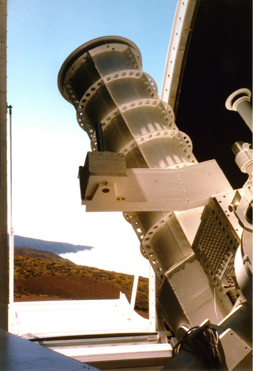
The GREGOR solar telescope (see e.g., von der Lühe et al. 2000, 2001a, 2001b, for early design concepts) supplanted the Gregory-Coudé Telescope (GCT, see Fig. 1) at Observatorio del Teide, Tenerife, Spain in 2002. In a brief history of the GCT, Wiehr (2003) emphasized the outstanding straylight properties of Gregory-type telescopes and pointed to the GCT’s excellent polarimetric properties, which are related to its German-type coudé mounting and various optical means to compensate instrumental polarization. The GREGOR project inherited the optical design that had been developed for a scaled-down, open-telescope version of the Large Earth-based Solar Telescope (LEST, Andersen, Engvold & Owner-Petersen 2002), while the LEST foundation had to be resolved due to insufficient funding. The science objectives as laid out in the original GREGOR proposal and recounted by Schmidt et al. (2012) are: (1) the interaction between convection and the magnetic field in the photosphere, (2) solar magnetism and its role in driving solar variability, (3) the enigmatic heating mechanisms of the chromosphere, and (4) the search for solar twins during nighttime.
A series of review articles and status reports accompanied the construction and commissioning phases of the GREGOR telescope (Balthasar et al. 2007; Schmidt et al. 2012; Volkmer et al. 2003b, 2004, 2005, 2006, 2007, 2010a, 2010b). Substantial efforts were devoted to the design and construction of the main optics from advanced Cesic® ceramics (e.g., Volkmer et al. 2003b, 2006). Problems in manufacturing such a mirror ultimately led to a significant delay of the GREGOR project, which finally reverted to a light-weighted Zerodur® mirror (Volkmer et al. 2010a, b). The progress of the project can be tracked in the reviews as critical milestones were reached: remodeling of the GREGOR building, installation of the foldable tent dome, telescope control systems (Volkmer et al. 2004); completion and installation of the telescope structure with subsequent pointing, tracking, and thermal tests (Volkmer et al. 2005); preparation of the optical laboratory for the adaptive optics (AO) system and post-focus instruments, start of integration of the main optics (Volkmer et al. 2006); installation of the interim 1-meter SolarLite mirror and cooling system tests, integration of AO system and post-focus instruments, start of commissioning (Volkmer et al. 2010a, b).
2 Foldable tent dome
The Dutch Open Telescope (DOT) already included many ingredients of the “open principle” (Hammerschlag et al. 2009), which were ultimately integrated into the GREGOR telescope, i.e., wind-flushing of the main optical path, a cooled field/heat stop in the primary focus, removal of all heat sources from the observing deck, passive means to keep the telescope structure in thermal equilibrium with its surroundings, a sturdy structure to prevent telescope shake by winds, and absence of any large objects near the telescope.
The GREGOR foldable-tent dome consists of double membranes stretched between a movable steel-bow structure (Bettonvil et al. 2007, 2008). The double-clothed tent improves thermal insulation and prevents condensation, while the tension force stabilizes the structure when the two shells of dome are closed. The dome has been in operation since 2006 and already survived major storms with strong winds of up to 70 m s-1. The two halves of the dome can be opened and closed at wind speeds of up to 30 m s-1. The smooth Teflon coating of the polyvinylidene fluoride (PVDF) tent cloth minimizes snow and ice loads.
The DOT and GREGOR domes are prototypes (Hammerschlag et al. 2010, 2012) envisioned for even larger constructions such as the European Solar Telescope (EST). Therefore, both domes were equipped with a suite of sensors, e.g., wind and pressure sensors as well as optical triangulation sensors (Jägers et al. 2008) to measure deformations of the tent dome and its performance in harsh/severe weather conditions. First results from the three-dimensional dome displacement (3DD3) sensors were presented in Sliepen et al. (2008), which was followed up by a comprehensive analysis including all sensors (Sliepen et al. 2010).
3 Telescope structure
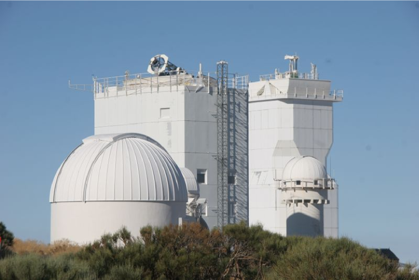
The GREGOR telescope (see Fig. 2) with its open-truss steel structure has to operate at wind speed of up to 20 m s-1, once the tent dome is completely opened. In this environment, telescope seeing has to be avoided and the influence of the wind blowing through the open telescope structure has to be minimized. Emde et al. (2003) carried out finite element analyses and time-history simulations of the structural response to static and dynamic wind loads. They concluded that the absolute pointing accuracy is better than 1\arcsec (rms) for all combinations of elevation and azimuth. Furthermore, the rms-wavefront errors resulting from static and dynamic deformations of the telescope are less than .
4 Thermal control
An open-telescope design requires a strict control of the thermal environment. The telescope structure should be within to K with the ambient temperature, and the temperature differential of the primary mirror should be less than 2 K. Emde et al. (2004) introduced the active and passive measures taken to offset the deleterious effects of telescope and mirror seeing. These precautions include sunshields to protect the telescope structure from direct sunlight and surface coatings (TiO2 paint and metallic foils). The thermal control concept for telescope structure and primary mirror (air cooling from the backside) were validated with finite element analyses (Emde et al. 2004) and direct as well as contactless measurements (Volkmer 2008). The most recent cooling system tests (Volkmer et al. 2010a, b) indicate only negligible temperature differentials between ambient air and primary mirror.
5 Telescope optics
The light-weighted primary mirror made from Zerodur® ceramics has an aperture with a diameter mm. It is a paraboloid with a focal length of mm (e.g., von der Lühe et al. 2001a). The double Gregory configuration with two elliptical Cesic® mirrors ( mm, mm, mm, and mm) facilitates placing a field stop in the primary focus and a polarization calibration unit in the secondary focus. Volkmer et al. (2003b) illustrated the tight geometry of the light beam in the vicinity of the heat stop (primary focus) and the polarization calibration unit (secondary focus). The alignment of the secondary mirror with respect to the primary mirror is critical for the optical quality of the telescope. Therefore, the secondary mirror is mounted on a hexapod, where it can be positioned with high precision in the micrometer and 10-rad range. Alignment constraints are less critical for the tertiary mirror, which is mounted behind the primary mirror and illuminated through a central hole with a diameter of 380 mm. Accordingly, the tertiary is used for focusing the telescope. The effective focal length of the telescope is mm resulting in a focal ratio and an image scale of 3.5\arcsec mm-1 in the science focus. A field-of-view (FOV) with a maximal diameter of 300\arcsec can be observed. Currently, the heat stop restricts the FOV to a circular area with a diameter of 180\arcsec. A comparison of the VTT and GREGOR thoeretical modulation transfer functions was presented in Soltau et al. (2003).
5.1 Ceramic mirrors
The GREGOR telecope was the first major solar telescope condering Cesic® ceramics for its main optics. The initial optical design envisioned that the primary, secondary, and tertiary mirrors were all made from this silicon-carbide composite material. This choice was driven by the desire to have a light-weight, stiff optics that can be effectively cooled to avoid mirror seeing (see Volkmer et al. 2003a). In the end, only the secondary and tertiary mirrors used this advanced material. The manufacturing process of the Cesic® ceramic mirrors is described in Krödel, Luichtel & Volkmer (2006), who recount all manufacturing steps from creating, light-weighting, milling, and fusing the greenbody segments – over Si-infiltration of the mirror blanks and coating of the mirror surfaces with a Si-SiC slurry – to finally, lapping, polishing, and testing of the mirrors. Once it became clear that the Cesic® technology was not sufficiently mature to create a large-aperture primary mirror, a more conventional approach was chosen using Zerodur® as the mirror substrate. The impacts on mirror design and support cell are laid out in Süß, Volkmer, & Eisenträger (2010), whereas fabrication issues were presented by Westerhoff et al. (2010), who also discuss aggressively light-weighted designs for mirrors with up to 4-m diameter.
5.2 GREGOR polarimetric unit
The polarimetric projects at the GREGOR solar telescope were summarized in Hofmann (2007, 2008). The general formalism to calibrate the instrumental polarization of the GREGOR telescope was set forth in Balthasar et al. (2011), which accounts for all mirrors of the alt-azimuthally mounted telescope, the mirrors and vacuum windows of the coudé train, and an optional image derotator. The goal is to reach a polarimetric sensitivity at the level in terms of the continuum intensity. The GREGOR Polarimetric Unit (GPU, Hofmann & Rendtel 2003) was developed to this end, serving all post-focus instruments in the visible and near-infrared. The GPU is located in the shadow of the Nasmyth mirror close to the secondary focus of the telescope, where it calibrates all instrumental polarization occurring between the tertiary mirror and the polarimeters of the post-focus instruments. The instrumental polarization introduced by the on-axis primary and secondary mirrors is at or below the level and can be neglected. The GPU is also used to evaluate the performance of the polarimeters used in the post-focus instruments. The GPU consists of two motorized wheels, which contain positions for a pinhole, a target, free apertures, and precision rotation mounts for a linear polarizer (Marple-Hess prism) and polymethylmetcrylat (PMMA) waveplates. The GPU was initially tested at the solar observatory “Einsteinturm” in Potsdam. The procedures to derive the extinction ratios of the linear polarizer, the wavelength dependency of the retarders, and their efficiency to generate circular polarized light were meticulously described in Hofmann, Rendtel & Arlt (2009).
5.3 Adaptive optics
The scientific potential of modern solar telescope is substantially enhanced by AO systems. The first design specifications for a “first-light” AO system were laid out by von der Lühe, Berkefeld & Soltau (2002) aiming at a diffraction-limited performance of the GREGOR solar telescope for the quarter of observing time with the best seeing conditions. The final design evolved significantly over the years (Berkefeld, Soltau & von der Lühe 2004, 2005, 2006; Berkefeld et al. 2012) and inherited many features of the Kiepenheuer Adaptive Optics System (KAOS), which has been reliably operated at the Vacuum Tower Telescope (VTT, see Fig. 2) for many years. This decade-long activity to develop solar AO systems also spun off to projects such as EST and the balloon-borne SUNRISE telescope (Berkefeld et al. 2010).
The GREGOR AO system uses a correlating Shack-Hartmann wavefront sensor. A high-cadence camera and high-performance computer provide a 2.5-kHz control loop frequency to achieve a 0-dB bandwidth of correction at about 130 Hz. The correction of the image motion is offloaded to a separate tip-tilt mirror so that the deformable mirror actuators can effectively correct the non-linear wavefront aberrations. The optical design also includes an option for multi-conjugate adaptive optics (MCAO, e.g., Berkefeld et al. 2010; Schmidt et al. 2009, 2010; Schmidt & Berkefeld 2012). The MCAO system has been extensively tested at the Kiepenheuer-Institut and the VTT, which led to substantial improvements in the optical design, namely the location of the on- and off-axis wavefront sensor. Thus, intensity fluctuations of a few percent (“flying-shadows”) caused by a warped pupil image could simply be removed by a slightly undersized pupil stop. The controlled FOV of the MCAO system has a diameter of about 60\arcsec, which is about ten times larger than what can be achieved with conventional AO.
The primary mirror’s small radius of curvature necessitates a high-degree of control over the secondary that is mounted on a hexapod. The DC components of the wavefront sensor signals encompass the wavefront aberrations of all optical elements in front of the wavefront sensor. Soltau, Berkefeld & Volkmer (2006) described the use of the AO system as commissioning tool for telescope alignment by solving the inversion problem of extracting the alignment parameters from the response matrix of the actuators.
6 Post-focus instruments
The initial plans for the GREGOR post-focus instrumentation (e.g., Kneer et al. 2001) included proposals for visible-light and infrared spectrographs, slit-jaw devices, polarimeters, broad-band imagers, and an imaging spectropolarimeter. Only the visible-light Czerny-Turner spectrograph and an adaption of the Polarimetric Littrow Spectrometer (POLIS, Schmidt et al. 2003) were not included in the suite of “first-light” instruments. Dichroic pentaprisms are used to split the light between the visible and infrared wavelengths. This photon-efficient set-up enables simultaneous multi-wavelength observations with several instruments. Similarly, a high-performance notch filter using thin-film optical coatings on a pentaprism (Schallenberg et al. 2010) sends only light within a band of 10–15 nm centered at 500 nm to the wavefront sensor of the AO system.
6.1 Grating Infrared Spectrograph (GRIS)
The Grating Infrared Spectrograph (GRIS, Collados et al. 2008) is a Czerny-Turner spectrograph designed for high-spectral resolution ( 300,000–450,000) observations in the wavelength range from 1.0–1.8 m, e.g., the Si i m, He i m, and Fe i m () spectral lines. The spectrograph can be combined with the Tenerife Infrared Polarimeter (TIP-2). The slit-length is 70\arcsec and the image scale amounts to 0.135\arcsec pixel-1. Scanning a FOV of will take less than 20 min while recording full-Stokes spectra with signal-to-noise ratio of 1000:1. GRIS reaches the diffraction-limit of the telescope at m. Multi-wavelength observations are enabled by slit-jaw cameras and in combination with the GREGOR Fabry-Pérot Interferometer (GFPI).
6.2 GREGOR Fabry-Pérot Interferometer (GFPI)
Conceptually, Fabry-Pérot interferometers can be placed in a telecentric or collimated mounting. Kneer & Hirzberger (2001) discussed advantages and disadvantages of this choice and presented the first general ideas for an imaging spectrometer at the GREGOR solar telescope. The final optical layout of the GFPI (Denker et al. 2010; Puschmann et al. 2012a; Puschmann 2012b) can be found in Puschmann et al. (2007). The new instrument is based on the “Göttingen” Fabry-Pérot Interferometer, which received upgrades of the etalons, cameras and software in 2005 (Puschmann et al. 2006) and was outfitted with a polarimeter based on ferro-electric liquid crystals and a modified Savart plate in 2007 (Bello González & Kneer 2008; Balthasar et al. 2009). The GFPI was transferred from the VTT to the GREGOR solar telescope in 2009. The spectral resolution of the GFPI is about 250,000 in the wavelength range from 530–860 nm. Two spectral lines can be observed sequentially while covering a FOV of . A second Fabry-Pérot interferometer for the blue spectral region was proposed by Denker (2010), who addressed the opportunities but also the challenges for imaging spectropolarimetry brought forth by new large-format, high-cadence camera systems.
6.3 Broad-Band Imager (BBI)
A recently installed Broad-Band Imager (BBI) records large-format, high-cadence images, which are suitable for image restoration. Schmidt et al. (2012) presented its optical layout including a Foucault channel to measure the optical quality and performance of the telescope.
6.4 Gregor@night
Nighttime operation was foreseen since the inception of the GREGOR telescope (Volkmer et al. 2003a). The initial plans included a fiber-fed echelle double spectrograph with a spectral resolution of 100,000 covering two wavelength regions at 360–490 nm and 510–870 nm (Strassmeier et al. 2007). The unrestricted availability of the GREGOR telescope at night makes it an ideal choice for surveys of solar-type stars, the search for solar twins, and monitoring of stellar activity cycles (e.g., in the Ca ii H & K lines). Current plans call for an adaptation of the SOFIN spectrograph of the Nordic Optical Telescope (NOT).
7 Conclusions
The design, construction, and commissioning phases of the GREGOR project were described in about 60 articles in refereed journals and conference proceedings. This article summarizes this body of work and serves as a reference to this special issue of Astronomische Nachrichten/Astronomical Notes, which sums up the state of the GREGOR project at the end of the science verification phase in 2012.
Acknowledgements.
The 1.5-meter GREGOR solar telescope was build by a German consortium under the leadership of the Kiepenheuer-Institut für Sonnenphysik in Freiburg with the Leibniz-Institut für Astrophysik Potsdam, the Institut für Astrophysik Göttingen, and the Max-Planck-Institut für Sonnensystemforschung in Katlenburg-Lindau as partners, and with contributions by the Instituto de Astrofísica de Canarias and the Astronomical Institute of the Academy of Sciences of the Czech Republic. CD was supported by grant DE 787/3-1 of the Deutsche Forschungsgemeinschaft (DFG).References
- Andersen, Engvold & Owner-Petersen (2002) Andersen, T., Engvold, O., Owner-Petersen, M.: 2002, LEST Technical Report No. 64, Institute for Theoretical Astrophysics, University of Oslo
- Balthasar et al. (2007) Balthasar, H., von der Lühe, O., Kneer, F., et al.: 2007, in: P. Heinzel, I. Dorotovič, R.J. Rutten (eds.), The Physics of Chromospheric Plasmas, ASPC 368, p. 605
- Balthasar et al. (2009) Balthasar, H., Bello González, N., Collados, M., et al.: 2009, in: K.G. Strassmeier, A.G. Kosovichev, J.E. Beckmann (eds.), Cosmic Magnetic Fields: From Planets, to Stars and Galaxies, IAU Symp. 259, p. 665
- Balthasar et al. (2011) Balthasar, H., Bello González, N., Collados, M., et al.: 2011, in: J.R. Kuhn et al. (eds.), Solar Polarization Workshop 6, ASPC 437, p. 351
- Bello González & Kneer (2008) Bello González, N., Kneer, F.: 2008, A&A 480, 265
- Berkefeld, Soltau & von der Lühe (2004) Berkefeld, T., Soltau, D., von der Lühe, O.: 2004, in: D. Bonaccini Calia, B.L. Ellerbroek, R. Ragazzoni (eds.), Advancements in Adaptive Optics, SPIE 5490, p. 260
- Berkefeld, Soltau & von der Lühe (2005) Berkefeld, T., Soltau, D., von der Lühe, O.: 2005, in: R.K. Tyson, M. Lloyd-Hart (eds.), Astronomical Adaptive Optics Systems and Applications II, SPIE 5903, p. 219
- Berkefeld, Soltau & von der Lühe (2006) Berkefeld, T., Soltau, D., von der Lühe, O.: 2006, in: B.L. Ellerbroek, D. Bonaccini Calia (eds.), Advances in Adaptive Optics II, SPIE 6272, p. 05
- Berkefeld et al. (2010) Berkefeld, T., Soltau, D., Schmidt, D., von der Lühe, O.: 2010, Appl. Opt. 49, G155
- Berkefeld et al. (2012) Berkefeld, T., Schmidt, D., Soltau, D., et al.: 2012, in: Ellerbroek, B.L., Marchetti, E., Véran, J.P. (eds.), Adaptive Optics Systems III, SPIE 8447, p. 51
- Bettonvil et al. (2007) Bettonvil, F.C.M., Hammerschlag, R.H., Jägers, A.P.L., Sliepen, G.: 2007, in: Structural Architecture. Toward the Future Looking to the Past, Venice, p. 204
- Bettonvil et al. (2008) Bettonvil, F.C.M., Hammerschlag, R.H., Jägers, A.P.L., Sliepen, G.: 2008, in: E. Atad-Ettedgui, D. Lemke (eds.), Advanced Optical and Mechanical Technologies in Telescopes and Instrumentation, SPIE 7018, p. 1N
- Collados et al. (2008) Collados, M., Calcines, A., Díaz, J.J., et al: 2008, in: I.S. McLean, M.M. Casali (eds.), Ground-Based and Airborne Instrumentation for Astronomy II, SPIE 7014, p. 5Z
- Denker (2010) Denker, C.: 2010, AN 331, 648
- Denker et al. (2010) Denker, C., Balthasar, H., Hofmann, A., et al.: 2010, in: I.S. McLean, S.K. Ramsay, H. Takami (eds.), Ground-Based and Airborne Instrumentation for Astronomy III, SPIE 7735, p. 6M
- Emde et al. (2003) Emde, P., Süß, M., Eisenträger, P., et al.: 2003, in: W.A. Goodman (ed.), Optical Materials and Structures Technologies, SPIE 5179, p. 282
- Emde et al. (2004) Emde, P., Kühn, J., Weis, U., Bornkessel, T.: 2004, in: J. Antebi, D. Lemke (eds.), Astronomical Structures and Mechanisms Technology, SPIE 5495, p. 238
- Hammerschlag et al. (2009) Hammerschlag, R.H., Bettonvil, F.C.M., Jägers, A.P.L., Sliepen, G.: 2009, Earth, Moon, & Planets 104, 83
- Hammerschlag et al. (2010) Hammerschlag, R.H., Kommers, J.N.M., van Leverink, S.J., et al.: 2010, in: L.M. Stepp, R. Gilmozzi, H.J. Hall (eds.), Ground-Based and Airborne Telescopes III, SPIE 7733, p. 0J
- Hammerschlag et al. (2012) Hammerschlag, R.H., Kommers, J.N., Visser, S., et al.: 2012, in: Navarro, R., Cunningham, C.R., Pietro, E. (eds.), Modern Technologies in Space-and Ground-Based Telescopes and Instrumentation II, SPIE 8450, p. 07
- Hofmann (2007) Hofmann, A.: 2007, Sun & Geosphere 2, 9
- Hofmann (2008) Hofmann, A.: 2008, Centr. Eur. Astrophys. Bull. 32, 17
- Hofmann & Rendtel (2003) Hofmann, A., Rendtel, J.: 2003, in: S. Fineschi (ed.), Polarimetry in Astronomy, SPIE 4843, p. 112
- Hofmann, Rendtel & Arlt (2009) Hofmann, A., Rendtel, J., Arlt, K.: 2009, Centr. Eur. Astrophys. Bull. 33, 317
- Jägers et al. (2008) Jägers, A.P.L., Sliepen, G., Bettonvil, F.C.M., Hammerschlag, R.H.: 2008, in: E. Atad-Ettedgui, D. Lemke (eds.), Advanced Optical and Mechanical Technologies in Telescopes and Instrumentation, SPIE 7018, p. 1R
- Kneer & Hirzberger (2001) Kneer, F., Hirzberger, H.: 2001, AN 322, 375
- Kneer et al. (2001) Kneer, F., Hofmann, A., von der Lühe, O., et al.: 2001, AN 322, 361
- Krödel, Luichtel & Volkmer (2006) Krödel, M.R., Luichtel, G., Volkmer, R.: 2006, in: E. Atad-Ettedgui, D. Lemke (eds.), Optomechanical Technologies for Astronomy, SPIE 6273, p. 0Q
- Puschmann et al. (2006) Puschmann, K.G., Kneer, F., Seelemann, T., Wittmann, A.D.: 2006, A&A 451, 1151
- Puschmann et al. (2007) Puschmann, K.G., Kneer, F., Nicklas, H., Wittmann, A.D.: 2007, in: F. Kneer, K.G. Puschmann, A.D. Wittmann (eds.), Modern Solar Facilities – Advanced Solar Science, p. 45
- Puschmann et al. (2012a) Puschmann, K.G., Balthasar, H., Bauer, S.-M., et al.: 2012a, in: Magnetic Fields from the Photosphere to the Corona, Rimmele, T.R. (ed.), ASPC, ArXiv e-prints, 1111.5509
- Puschmann (2012b) Puschmann, K.G., Balthasar, H., Popow, E.,et al.: 2012b, in: McLean, I.S., Ramsay, S.K., Takami, H. (eds.), Ground-Based and Airborne Instrumentation for Astronomy IV, SPIE 8446, p. 276
- Schallenberg et al. (2010) Schallenberg, U., Ploss, B., Lappschies, M., Jakobs, S.: 2010, in: E. Atad-Ettedgui, D. Lemke (eds.), Modern Technologies in Space- and Ground-Based Telescopes and Instrumentation, SPIE 7739, p. 1X
- Schmidt et al. (2009) Schmidt, D., Berkefeld, T., Heidecke, F., et al: 2009, in: P.G. Warren et al. (eds.), Astronomical and Space Optical Systems, SPIE 7439, p. 0X
- Schmidt et al. (2010) Schmidt, D., Berkefeld, T., Feger, B., Heidecke, F.: 2010, in: B.L. Ellerbroek et al. (eds.), Adaptive Optics Systems II, SPIE 7736, p. 07
- Schmidt & Berkefeld (2012) Schmidt, D., Berkefeld, T.: 2012, in: Ellerbroek, B.L., Marchetti, E., Véran, J.P. (eds.), Adaptive Optics Systems III, SPIE 8447, p. 128
- Schmidt et al. (2003) Schmidt, W., Beck, C., Kentischer, T., et al.: 2003, AN 324, 300
- Schmidt et al. (2012) Schmidt, W., von der Lühe, O., Volkmer, R., et al.: 2012, in: Magnetic Fields from the Photosphere to the Corona, Rimmele, T.R. (ed.), ASPC, ArXiv e-prints, 1202.4289
- Sliepen et al. (2008) Sliepen, G., Jägers, A.P.L., Bettonvil, F.C.M., Hammerschlag, R.H.: 2008, in: E. Atad-Ettedgui, D. Lemke (eds.), Advanced Optical and Mechanical Technologies in Telescopes and Instrumentation, SPIE 7018, p. 1C
- Sliepen et al. (2010) Sliepen, G., Jägers, A.P.L., Hammerschlag, R.H., Bettonvil, F.C.M.: 2010, in: L.M. Stepp, R. Gilmozzi, H.J. Hall (eds.), Ground-Based and Airborne Telescopes III, SPIE 7733, p. 32
- Soltau, Berkefeld & Volkmer (2006) Soltau, D., Berkefeld, T., Volkmer, R.: 2006, in: L.M. Stepp (ed.), Ground-Based and Airborne Telescopes, SPIE 6267, p. 11
- Soltau et al. (2003) Soltau, D., Berkefeld, T., von der Lühe, O., et al.: 2003, AN 324, 292
- Strassmeier et al. (2007) Strassmeier, K.G., Woche, M., Granzer, T., et al.: 2007, in: F. Kneer, K.G. Puschmann, A.D. Wittmann (eds.), Modern Solar Facilities – Advanced Solar Science, p. 51
- Süß, Volkmer, & Eisenträger (2010) Süß, M., Volkmer, R., Eisenträger, P.: 2010, in: E. Atad-Ettedgui, D. Lemke (eds.), Modern Technologies in Space- and Ground-Based Telescopes and Instrumentation, SPIE 7739, p. 1I
- Volkmer (2008) Volkmer, R.: 2008, in: L.M. Stepp, R. Gilmozzi (eds.), Ground-Based and Airborne Telescopes II, SPIE 7012, p. 0K
- Volkmer et al. (2003a) Volkmer, R., von der Lühe, O., Soltau, D., et al.: 2003a, in: W.A. Goodman (ed.), Optical Materials and Structures Technologies, SPIE 5179, p. 270
- Volkmer et al. (2003b) Volkmer, R., von der Lühe, O., Kneer, F.: 2003b, in: S.K. Keil, S.V. Avakyan (eds.), Innovative Telescopes and Instrumentation for Solar Astrophysics, SPIE 4853, p. 360
- Volkmer et al. (2004) Volkmer, R., von der Lühe, O., Kneer, F., et al.: 2004, in: J.M. Oschmann (ed.), Ground-Based Telescopes, SPIE 5489, p. 693
- Volkmer et al. (2005) Volkmer, R., von der Lühe, O., Kneer, F., et al.: 2005, in: S. Fineschi, R.A. Viereck (eds.), Solar Physics and Space Weather Instrumentation, SPIE 5901, p. 75
- Volkmer et al. (2006) Volkmer, R., von der Lühe, O., Kneer, F., et al.: 2006, in: L.M. Stepp (ed.), Ground-Based and Airborne Telescopes, SPIE 6267, p. 0W
- Volkmer et al. (2007) Volkmer, R., von der Lühe, O., Kneer, F., et al.: 2007, in: F. Kneer, K.G. Puschmann, A.D. Wittmann (eds.), Modern Solar Facilities – Advanced Solar Science, p. 39
- Volkmer et al. (2010a) Volkmer, R., von der Lühe, Denker, C., et al.: 2010a, AN 331, 624
- Volkmer et al. (2010b) Volkmer, R., von der Lühe, Denker, C., et al.: 2010b, in: L.M. Stepp, R. Gilmozzi, H.J. Hall (eds.), Ground-Based and Airborne Telescopes III, SPIE 7733, p. 0K
- von der Lühe, Berkefeld & Soltau (2002) von der Lühe, O., Berkefeld, T., Soltau, D.: 2002, in: A. Kohnle, J.D. Gonglewski, T.J. Schmugge (eds.), Optics in Atmospheric Propagation and Adaptive Systems IV, SPIE 4538, p. 197
- von der Lühe et al. (2000) von der Lühe, O., Schmidt, W., Soltau, D., et al.: 2000, in: A. Wilson (ed.), The Solar Cycle and Terrestrial Climate, Solar and Space Weather, ESA SP 463, p. 629
- von der Lühe et al. (2001a) von der Lühe, O., Schmidt, W., Soltau, D., et al.: 2001a, AN 322, 353
- von der Lühe et al. (2001b) von der Lühe, O., Schmidt, W., Soltau, D., et al.: 2001b, in: B. Battrick et al. (eds.), Solar Encounter, ESA SP 493, p. 417
- Westerhoff et al. (2010) Westerhoff, T., Schäfer, M., Thomas, A., et al.: 2010, in: E. Atad-Ettedgui, D. Lemke (eds.), Modern Technologies in Space- and Ground-Based Telescopes and Instrumentation, SPIE 7739, p. 0M
- Wiehr (2003) Wiehr, E.: 2003, AN 324, 285