Quantum circuits for amplification of Kerr nonlinearity via quadrature squeezing
Abstract
Phase shifts induced by the Kerr effect are usually very small at the single-photon level. We propose two circuits for enhancing the cross-Kerr phase shift by applying one- and two-mode quadrature squeezing operators. Our results are based on the vector coherent state theory and can be implemented by physical operations satisfying the commutation relations for generators of the generalized special unitary group SU(1,1). While the proposed methods could be useful for the realization of quantum optical entangling gates based on Kerr nonlinear media at the single-photon level, they also indicate a general alternative approach to enhance higher-order nonlinearities by applying lower-order nonlinear effects.
pacs:
42.50.Ex,42.50.Dv,42.50.-pI Introduction
The optical Kerr effect has been attracting considerable interest in quantum state engineering (see, e.g., Refs. HarocheBook ; GerryBook ) for, e.g., self-focusing, self-phase modulation, photon blockade (also referred to as optical state truncation) blockade1 ; blockade2 and quantum nondemolition measurements QND1 ; QND2 as demonstrated in a number of experiments (see HarocheBook for references). Moreover, the Kerr effect can be used for a generation of nonclassical light Tanas03 including self-squeezed light KerrSqeezing and macroscopic quantum superpositions, i.e., the so-called Schrödinger cat Yurke86 and kitten Miranowicz90 states.
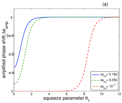
The optical Kerr effect is also a potential resource for performing deterministic photon interactions for quantum information processing (see, e.g., Refs. GerryBook ; Milburn89 ). Unfortunately, the Kerr effect is usually very weak at the single-photon level. Moreover, recent studies showed Shapiro06 ; Gea10 ; Fan13 that the phase noise in the cross-Kerr interaction of small numbers of photons could be significant and, thus, could preclude an effective implementation of entangling gates, like the conditional phase (CPHASE) gate, at the single-photon level. Nevertheless, recent experiments demonstrate the possibility to effectively produce, control and measure a non-zero conditional phase shift induced by a cross-Kerr modulation for very weak light. For example, Fushman et al. Fushman08 measured nonlinear Kerr-like phase shifts of 0.05 (9 degrees) in a single quantum dot coupled to a photonic crystal nanocavity at the single-photon level. The maximum observed phase shift in this report was equal to 0.16 (28.8 degrees). The average nonlinear cross–Kerr phase shifts of up to 20 degrees per photon at the single-photon level was observed by Hoi et al. Hoi13 in their recent experiments with coherent microwave radiation generated in superconducting circuits based on Josephson junctions. By comparison, Matsuda et al. Matsuda09 measured the nonlinear Kerr phase shifts of rad in optical fibres in single-shot experiments at the single-photon level. The reported nonlinear phase shift can be increased to for fibers of the same nonlinearity but with a reduced loss of 1 dB/km and flattened group-velocity dispersion Matsuda09 .
The effective Hamiltonian describing cross-Kerr interaction between modes and can be given as GerryBook :
| (1) |
where is the (rescaled) third-order susceptibility of the nonlinear medium, and are the photon-number operators given in terms of the annihilation ( and ) and creation ( and ) operators. We analyze photon-number qubits as superpositions of vacuum and single-photon Fock states. Using an appropriate strong cross-Kerr interaction, it is possible to perform the CPHASE gate on two qubits in such a way that the states and are unchanged, but the two single-photon states gain some additional phase , i.e., In particular, for , the CPHASE gate becomes the controlled-sign (CSIGN) gate, which is equivalent (up to a unitary transformation) to the controlled-NOT (CNOT) gate.
The main aim of our paper is to show how squeezing can be applied to increase the cross-Kerr nonlinearity.
Squeezed light is a useful resource in high-precision metrology and quantum information processing including quantum communication (e.g., for quantum entanglement distribution) and quantum cryptography (e.g., for secure quantum key distribution) BraunsteinBook . The following values of quadrature squeezing were experimentally observed in continuous-wave optical fields: -9 dB Takeno07 , -10 dB (-13 dB) Vahlbruch07 , -11.5 dB Mehmet10 , and -12.7 dB Eberle10 . The value of -13 dB is the estimation of squeezing achieved in the experiment Vahlbruch07 after correction for detector inefficiency, which results in a 5% improvement Polzik08 . Recently, a few experiments with superconducting circuits Wilson11 ; Flurin12 have demonstrated the possibility of obtaining much stronger squeezing in microwave fields, even much exceeding -20 dB below the shot-noise level Delsing13 . Squeezing of light pulses, which is more adequate for our circuits, is typically much weaker than continuous-mode squeezing. Probably, the highest reported experimental pulse-mode squeezing is only about -3 dB below the shot-noise level: -3 dB Wenger04 , -3.1 dB Takahashi08 , and -3.2 dB Eto07 .
Our amplification circuits are described in detail in the next sections. We summarize our amplified Kerr shifts for the above experimentally relevant squeezing values in table I and Conclusions.
II Circuit based on single-mode squeezing
First we present a two-mode circuit for the amplification of the phase shift induced by the nonlinear cross-Kerr effect using one-mode squeezing operators. Our derivation is based on the vector coherence theory (for a review, see Zhang90 ).
Let us consider only a two-qubit subspace of the total photon-number space and define qubit states with photon numbers and as and , respectively. Therefore, in this subspace used for quantum computation, we can introduce the operator , which has only two eigenvalues equal to and , so that . This operator can be further used to construct one of the generators of the SU(1,1) group,
| (2) |
which is equivalent (up to some additional phase shift of both qubits) to the Kerr effect described by equation (1). In order to preserve the bosonic commutation rules for the generators of SU(1,1):
| (3) |
we construct the remaining generators as follows:
| (4) |
where and fulfill the standard bosonic commutation relation. Using the vector coherent-state theory, we find a configuration of operations, which need to be performed on qubits to amplify the conditional phase shift induced by the cross-Kerr effect. The vector coherent-state theory is based on the fact that structural constants depend only on the commutation relations of generators, but they are independent of the dimensions of the representations of those generators, for example of the group SU(1,1),
| (5) |
where, for given and , the structural constants , and are independent of the dimension of The generators of the group SU(1,1), which is noncompact and does not have any finite unitary representation, can, however, be written in a simple two-dimensional non-Hermitian representation as:
| (8) | |||||
| (11) | |||||
| (14) |
According to equation (14), we can design the following setup for enhancing Kerr nonlinearity:
| (15) |
where the coefficients and are introduced via the angles and as follows:
| (16) |
The above result can be obtained as follows:
| (21) | |||
| (26) |
where
| (29) | |||||
| (30) |
and . In equation (26), the exponential functions of are group elements, which can be given in a matrix representation. Although there is no finite unitary representation of the group, we have checked our result also numerically for spaces of relatively large dimension (up to 100).
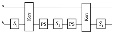
According to equation (15), it is possible to design the following method for the Kerr-nonlinearity amplification:
| (31) |
where PS denotes (linear) phase shift in mode . Based on the vector coherence theory, we conclude that these relations are valid in the whole ladder of Fock states for the mode . For the mode , we restrict ourselves within the subspace of the vacuum and single-photon states. The unitary operation [connected with the exponents of given in equation (4)] corresponds to the standard single-mode (quadrature) squeezing operator GerryBook :
| (32) |
where the squeezing parameter (with =1,2) is assumed to be real and extra minus corresponds to the squeezing angle equal to . This squeezing operator can be implemented by a degenerate parametric down-conversion described by the interaction Hamiltonian
| (33) |
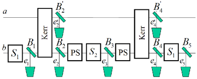
in the strong classical pump limit, where the operator is well approximated by a complex number . The interaction strength is proportional to the second-order susceptibility, , of the nonlinear medium. Thus, this is a lower-order nonlinear process in comparison to the Kerr effect given by equation (1). For completeness, we note that this squeezing operator can be also realized by higher-order nonlinear processes, e.g., described by . The circuit, shown in figure 1 and given by equations (15) and (31), can be compactly rewritten as:
| (34) |
where the operators describe the initial and amplified Kerr effects, corresponding to the interaction strengths
| (35) |
respectively. Moreover in equation (34), and are linear phase shifts with and . The right-hand side of equation (34) is shown in figure 1 where, for simplicity, the less important gate is omitted.
One can define the cross-Kerr effect amplification factor as the ratio of the amplified, , and initial, , cross-Kerr phase shifts:
| (36) |
Alternatively, one could define , where factor 2 in the denominator would count for two Kerr media used in this circuit (see figure 1). In table I, we calculated this amplification factor for the best experimentally achieved values of the squeezing parameters and the cross-Kerr phase shifts .
| reference | |||||||
|---|---|---|---|---|---|---|---|
| [dB] | [rad] | [deg] | [deg] | ||||
| -3 | Wenger04 ; Takahashi08 ; Eto07 p | 0.35 | 2.12 | 2.12 | 19.10 | 2.13 | 61.40 |
| -9 | Takeno07 c | 1.04 | 3.17 | 3.19 | 28.70 | 3.46 | 99.700 |
| -10 | Vahlbruch07 c | 1.15 | 3.48 | 3.51 | 31.60 | 3.95 | 113.80 |
| -11.5 | Mehmet10 c | 1.32 | 4.02 | 4.08 | 36.70 | 5.26 | 151.60 |
| -13 | Eberle10 ; Vahlbruch07 c | 1.50 | 4.69 | 4.78 | 43.00 | — | 180.00 |
| -20 | 2.30 | 10.10 | 11.60 | 104.40 | — | 180.00 |
As already emphasized, Kerr effect is usually very small at the single-photon level, i.e., . Let us also assume that the squeezing parameter is relatively small such that . Then, by expanding equations (16) in power series in and keeping only the first terms of these expansions, one finds that and
| (37) |
which results in the Kerr amplification factor
| (38) |
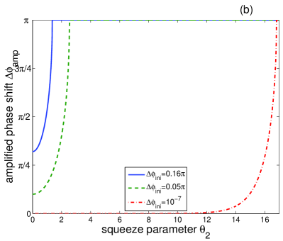
being independent of . The enhancements of the cross-Kerr phase shift vs. squeezing parameters and are plotted in figure 2 for experimental (initial) nonlinear phase shifts reported by Matsuda et al. Matsuda09 and Fushman et al. Fushman08 . As can be seen in figure 2 and table I, we obtain a significant enhancement of the Kerr nonlinearity. As it turns out, when an appropriate squeezed light goes through two Kerr crystals and phase shifters, the Kerr nonlinearity can be amplified to a shift. Thus, the CPHASE gate can be, in principle, deterministically implemented by Kerr nonlinearity via the cross-phase modulation if appropriately strong squeezing of light is available.
III Circuit based on two-mode squeezing
Here we present a three-mode circuit for the amplification of Kerr effect based on two-mode squeezing as an extension of the two-mode circuit of the former section.
The two-mode squeezing operator acting on modes and can be defined as GerryBook :
| (39) |
with the real squeezing parameter . This two-mode squeezing operator can be implemented by a nondegenerate parametric down-conversion in a -nonlinear medium as described by the interaction Hamiltonian
| (40) |
assuming that the strong pump mode is treated classically, i.e., , in analogy to the degenerate case described by equation (33). Also analogously to equations (2) and (4), the generators of the group SU(1,1) can be written as:
| (41) |
with the same commutation relations as those given by equation (3) for . Based on equation (15) we can derive the following relation:
| (42) |
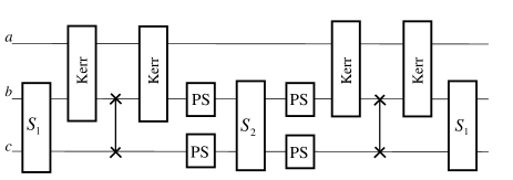
In analogy to the circuit of section II, this three-mode circuit with the two-mode squeezing operators can be compactly written in the form of equation (34), but for and , where and for and is the phase shift with . The final Kerr effect enhancement in this circuit is similar to the former circuit. Note that figure 3 shows a circuit composed of Kerr effect operators applied in modes and solely. We have simply applied the relation in terms of the SWAP operations .
IV Dissipation
In order to include the effect of decoherence in our circuits, we apply the beam-splitter model of losses, which was developed in a general form by Leonhardt Leonhardt93 and d’Ariano DAriano94 .
Realistic imperfect nonlinear elements (i.e., the squeezers and Kerr elements) of the proposed circuits can be modelled as the perfect ones followed by fictitious beam splitters (for ), as shown in figure 4. The vacuum mode, assumed at one of the input ports of each beam splitter, models the extra quantum noise caused by the nonlinear effects.
Note that we ignore dissipation in phase shifters. In fact, losses involved in linear optical elements (such as phase shifters and beam splitters) are usually negligible in comparison to those of realistic nonlinear optical elements.
As discussed in Leonhardt93 ; Kiss95 , the model of losses, based on a single-beam splitter, formally corresponds to a dissipation described by the standard master equation for a quiet reservoir (i.e., at zero temperature) as given by
| (43) |
In this description, the formal time is simply related to the reflectance as at the beam splitter.
The circuit shown in figure 4 (except the additional phase shifter ) performs the following sequence of operations
| (44) |
where . The beam-splitter transformations () for the annihilation operators and ( and ) of the signal (vacuum) modes are given by
| (45) |
respectively, where and is the reflectance. Then, the output signal state is given by
| (46) |
as obtained by tracing out the beam-splitter output modes and , which are lost to the environment. In this equation, is the two-mode input signal state and with are the vacuum modes. It is rather inconvenient to directly apply equations (44) and (46) in numerical analysis. This would require dealing simultaneously with nine-mode Hilbert spaces. Instead of this, in our numerical simulation of losses, we have applied the required operations sequentially as follows:
| (47) |
according to the circuit shown in figure 4.
In order to compare the outputs of the perfect and lossy circuits, we apply the Uhlmann-Jozsa fidelity defined as BengtssonBook :
| (48) |
In our case, is the output state of the two-mode lossy circuit, given by equations (46) and (47), while is the ideal Kerr state obtained by the application of the operators given by the left- or right-hand side of equation (34) to a given initial state . Note that the root fidelity is also sometimes referred to as fidelity (see, e.g., NielsenBook ). Methods for measuring the fidelity and its tight upper and lower bounds are described in Bartkiewicz13b . If one of the states is pure, which can be the ideal state , then the fidelity simplifies to the straightforward expression .
For simplicity, we present our numerical results only for the cases when the losses in the signal modes in all the squeezers (Kerr media), as shown in figure 4, are the same and described by the reflectance (). If we set , then the amplified cross-Kerr phase shift is equal to for the ideal system.
Now we shortly discuss the results of our numerical simulations for the two specific choices of the input state. Our first example was calculated for an initial separable pure state, i.e., where . The perfect CPHASE gate should transform this state into an entangled state . In contrast, the imperfect amplifier generates a mixed state described by the fidelity depending on the chosen values of the losses (reflectances) and . For example, we found , , , and . We note that as required for the ideal amplifier, and for the amplifier absorbing completely the input state.
Our second example is given for an initial entangled mixed state, i.e., for the two-qubit Werner-like state defined by (see, e.g., Miran04 )
| (49) |
where and is the identity operator. Moreover, we set (in general, ). As in the former case we assume , which leads to in the ideal system. The calculated fidelities as a function of the losses (reflectances) and read as: , , , and . Note that, as for the former example, it holds for . This can be interpreted that our circuit is more sensitive to losses in the Kerr media rather than those in the squeezers at least for the analyzed values and states within our beam-splitter model of losses. In addition, as expected for the ideal case, and for the amplifier absorbing all the incident light.
Finally, we mention that a deeper analysis of decoherence in our circuits should also include the effect of thermal photons. This dissipation can be modelled by the full master equation assuming that the thermal reservoir is at non-zero temperature, which is a generalization of the quiet-reservoir master equation, given by (43). Such thermal effects can be described (to some extent) by the beam-splitter model of losses assuming that thermal photons, instead of the vacuum mode, are at one of the input modes to fictitious beam splitters. Preliminary studies show that our circuits are strongly sensitive to thermal photons which is typical, especially for nonlinear optical processes at the single-photon level. We also note about the effects of mode mismatch, which are important when dealing with time-frequency overlaps of interfering light pulses. Such mode-mismatch effects can affect efficiency of systems, which can be revealed by applying a pulse-mode formalism, as studied, e.g., in the related problem of a quantum scissors system Ozdemir02 . This infinite-mode formalism is completely different from that applied here for a few modes only. Our related theoretical Ozdemir02 and experimental studies Lemr12 show that usually the mode-mismatch problems can be effectively overcome in optical experiments even at the single-photon level.
V Conclusions
We proposed two setups which can be used for enhancing the phase shift in nonlinear cross-Kerr media, described by the third-order nonlinear susceptibilities , by applying a sequence of single-mode (or two-mode) squeezing operators in media described by the second-order nonlinear susceptibilities . Our results are based on a group-theoretical analysis. It is well known that entangling gates, like controlled-sign (CSIGN) gate, cannot be implemented deterministically using linear-optical elements only (for a review see Bartkowiak10 ). Our approach can, in principle, enhance the nonlinear phase shift to 1800 at the single-photon level and thus enable a deterministic implementation of the CSIGN gate if adequately strong squeezed light source is available.
Our group-theoretical proposal can be implemented using various systems exhibiting quadrature squeezing and cross-Kerr nonlinearity. The predicted enhanced nonlinear phase shifts for the experimentally observed initial nonlinear phase shifts and generated squeezings are summarized in table I.
We also studied dissipation in non-perfect circuits by applying the beam-splitter model of losses. In particular, we addressed the question how the Uhlmann-Jozsa fidelity, between the outputs of the ideal and lossy systems, deviates from 1 by the inclusion of losses.
Whilst we have proposed methods, which could be applied for an implementation of quantum entangling gates using Kerr media at the single-photon level, we have also shown an interesting general idea to enhance higher-order nonlinear effects through other types of lower-order nonlinear effects.
Acknowledgements. The authors thank Nobuyuki Matsuda and Patrick Leung for discussions. M.B. acknowledges a scholarship from the Adam Mickiewicz University to stay at the Basque Country University. This work was supported by the Polish National Science Centre under grants DEC-2011/03/B/ST2/01903 and DEC-2011/02/A/ST2/00305 the Basque Government (Grant No. IT472-10) and the Spanish MICINN (Project No. FIS2012-36673-C03-03).
References
- (1) Haroche S and Raimond J M 2006 Exploring the Quantum: Atoms, Cavities and Photons (Oxford: Oxford University)
- (2) Gerry C and Knight P 2006 Introductory Quantum Optics (Cambridge: Cambridge University)
- (3) Imamoḡlu A, Schmidt H, Woods G, and Deutsch M 1997 Phys. Rev. Lett. 79 1467
- (4) Leoński W and Tanaś R 1994 Phys. Rev. A 49 R20
- (5) Milburn G J and Walls D F 1983 Phys. Rev. A 28 2065
- (6) Imoto N, Haus H A, and Yamamoto Y 1985 Phys. Rev. A 32 2287
- (7) Tanaś R 2003 Theory of Non-Classical States of Light ed V Dodonov and V I Man’ko (London: Taylor & Francis) p 267
-
(8)
Tanaś R and Kielich S 1983 Opt. Commun. 45 351
Milburn G J 1986 Phys. Rev. A 33 674
Yamamoto Y, Imoto N, and Machida S 1986 Phys. Rev. A 33 3243 -
(9)
Yurke B and D Stoler 1986 Phys. Rev. Lett. 57 13
Tombesi P and Mecozzi A 1987 J. Opt. Soc. Am. B 4 1700 -
(10)
Miranowicz A, Tanaś R, and Kielich S 1990 Quantum Opt. 2 253
Tanaś R, Gantsog Ts, Miranowicz A, and Kielich S 1991 J. Opt. Soc. Am. B 8 1576 -
(11)
Milburn G J 1989 Phys. Rev. Lett. 62 2124
Chuang I L and Yamamoto Y 1995 Phys. Rev. A 52 3489
Franson J D, Jacobs B C, and Pittman T B 2004 Phys. Rev. A 70 062302
Nemoto K and Munro W J 2004 Phys. Rev. Lett. 93 250502
Munro W J, Nemoto K, and Spillter T P 2005 New J. Phys. 7 137
Leung P M and Ralph T C 2006 Phys. Rev. A 74 062325 -
(12)
Shapiro J H 2006 Phys. Rev. A 73 062305
Shapiro J H and Razavi M 2007 New J. Phys. 9 16 - (13) Gea-Banacloche J 2010 Phys. Rev. A 81 043823
- (14) Fan B, Kockum A F, Combes J, Johansson G, Hoi I C, Wilson C M, Delsing P, Milburn G J, and Stace T M 2013 Phys. Rev. Lett. 110 053601
- (15) Fushman I, Englund D, Faraon A, Stoltz N, Petroff P, and Vučković J 2008 Science 320 769
- (16) Hoi I C, Kockum A F, Palomaki T, Stace T M, Fan B, Tornberg L, Sathyamoorthy S R, Johansson G, Delsing P, and Wilson C M, Phys. Rev. Lett. 2013 111 053601
- (17) Matsuda N, Shimizu R, Mitsumori Y, Kosaka H, and Edamatsu K 2009 Nature Photon. 3 95
- (18) Quantum Information with Continuous Variables 2003 ed S L Braunstein and A K Pati (Berlin: Springer)
- (19) Takeno Y, Yukawa M, Yonezawa H, and Furusawa A 2007 Opt. Express 15 4321
- (20) Vahlbruch H, Mehmet M, Lastzka N, Hage B, Chelkowski S, Franzen A, Gossler S, Danzmann K, and Schnabel R 2008 Phys. Rev. Lett. 100 033602
- (21) Mehmet M, Vahlbruch H, Lastzka N, Danzmann K, and Schnabel R 2010 Phys. Rev. A 81 013814
- (22) Eberle T, Steinlechner S, Bauchrowitz J, Handchen V, Vahlbruch H, Mehmet M, Muller-Ebhardt H, and Schnabel R 2010 Phys. Rev. Lett. 104 251102
- (23) Polzik E S 2008 Nature 453, 45
- (24) Wilson C M, Johansson G, Pourkabirian A, Simoen M, Johansson J R, Duty T, Nori F, and Delsing P 2011 Nature 479 376
- (25) Flurin E, Roch N, Mallet F, Devoret M H, and Huard B 2012 Phys. Rev. Lett. 109 183901
- (26) Delsing P 2013 private communication.
- (27) Wenger J, Tualle-Brouri R, and Grangier P 2004 Opt. Lett. 29 1267
- (28) Takahashi Y, Söderholm J, Hirano K, Namekata N, Machida S, Mori S, Kurimura S, Komatsu S, and Inoue S 2008 Phys. Rev. A 77 043801
- (29) Eto Y, Tajima T, Zhang Y, and Hirano T 2007 Opt. Lett. 32 1698
- (30) Zhang W M, Feng D H, and Gilmore R 1990 Rev. Mod. Phys. 62 867
- (31) Leonhardt U 1993 Phys. Rev. A 48 3265
- (32) D’Ariano G M 1994 Phys. Lett. A 187 231
- (33) Kiss T, Herzog U, and Leonhardt U 1995 Phys. Rev. A 52 2433
- (34) Bengtsson I and Życzkowski K 2006 Geometry of Quantum States: An Introduction to Quantum Entanglement (Cambridge: Cambridge Unversity)
- (35) Nielsen M A and Chuang I L 2000 Quantum Computation and Quantum Information (Cambridge: Cambridge Unversity)
- (36) Bartkiewicz K, Lemr K, and Miranowicz A 2013 Phys. Rev. A 88 052104
- (37) Miranowicz A 2004 Phys. Lett. A 327 272
- (38) Özdemir Ş K, Miranowicz A, Koashi M, and Imoto N 2002 Phys. Rev. A 66 053809
-
(39)
Lemr K, Bartkiewicz K, Černoch A, Soubusta J, and
Miranowicz A
2012 Phys. Rev. A 85 050307(R)
Bartkiewicz K, Lemr K, Černoch A, Soubusta J, and Miranowicz A 2013 Phys. Rev. Lett. 110 173601
Bartkiewicz K, Černoch A, Lemr K, Soubusta J, and Stobińska M 2013 arXiv:1310.1768 - (40) Bartkowiak M and Miranowicz A 2010 J. Opt. Soc. Am. B 27 2369