Defect stability in phase-field crystal models: Stacking faults and partial dislocations
Abstract
The primary factors controlling defect stability in phase-field crystal (PFC) models are examined, with illustrative examples involving several existing variations of the model. Guidelines are presented for constructing models with stable defect structures that maintain high numerical efficiency. The general framework combines both long-range elastic fields and basic features of atomic-level core structures, with defect dynamics operable over diffusive time scales. Fundamental elements of the resulting defect physics are characterized for the case of fcc crystals. Stacking faults and split Shockley partial dislocations are stabilized for the first time within the PFC formalism, and various properties of associated defect structures are characterized. These include the dissociation width of perfect edge and screw dislocations, the effect of applied stresses on dissociation, Peierls strains for glide, and dynamic contraction of gliding pairs of partials. Our results in general are shown to compare favorably with continuum elastic theories and experimental findings.
pacs:
61.72.Bb, 61.72.Lk, 61.72.Nn, 62.20.F-I Introduction
Structural kinetics in crystalline solids are driven heterogeneously at the atomic level by localized defects, which in turn drive mesoscopic and macroscopic phenomena such as structural phase transformations, fracture, and other forms of plastic flow. A complete description of such processes therefore requires a multiscale approach. Existing modeling methods typically operate either exclusively on atomic scales or on meso- and macroscopic scales. Phase-field crystal models on the other hand provide a framework that combines atomic length scales and mesoscopic/diffusive time scales Elder et al. (2002); Elder and Grant (2004); Elder et al. (2007), with the potential to reach mesoscopic lengths through systematic multi-scale expansion methods Goldenfeld et al. (2005); Athreya et al. (2007); Yeon et al. (2010); Huang et al. (2010); Spatschek and Karma (2010).
The PFC approach naturally incorporates elasticity, plasticity, and effects of local crystal orientation into a relatively simple atomic-level continuum theory Elder et al. (2002); Elder and Grant (2004). The literature published to date demonstrates that such a formulation, with only a few minimal ingredients, gives rise to a broad range of physics associated with diffusive nonequilibrium processes in liquid and solid systems. One of its strengths in terms of describing periodic systems is the wealth of inherent defect structures that automatically emerge from the basic free energy functional. This permits the study of crystalline defects within a description that captures both long-range elastic fields and basic features of atomic-level core structures. In addition to fundamental, local defect properties, the role of these defects in dynamic materials phenomena that operate over long, diffusive time scales can be examined. Therefore, defect stability, the core structure of stable defect configurations, and the dynamics and interactions of various defect structures within the PFC description all become central issues as the method is advanced further into solid-state phenomena. However, in light of the approximations inherent to the approach, its limitations need to be adequately realized and understood as well.
The basic properties of perfect PFC crystals are relatively well understood, but the various classes and types of defects relevant to each given lattice symmetry require further study if material-specific applications are to be pursued. Perfect dislocations and simple grain boundaries in 2D triangular and 3D bcc crystals have been examined and are known to be topologically stable under typical conditions of small local strain and low thermodynamic driving force Elder and Grant (2004); Berry et al. (2006); Stefanovic et al. (2006, 2009); Hirouchi et al. (2009); Chan et al. (2010); Elder et al. (2007); Jaatinen et al. (2009); Backofen et al. (2010); Jaatinen et al. (2010); Berry et al. (2008); Mellenthin et al. (2008); Olmsted et al. (2011). Certain other defect structures, notably stacking faults in close-packed 3D crystals, have inherently lower topological stability, and in such cases the proper balance between crystal stability and defect stability in the model formulation becomes more restrictive and difficult to achieve. It is also not necessarily clear which of the now many versions of PFC are best suited for describing defect-mediated processes.
The aims of the first part of this article are to characterize the nature of defect stability in PFC models in terms of a few general model features, and to examine how various versions compare in this respect. We will show that fine control of crystal structure often leads to reduced defect stability. A balance must therefore be found that sufficiently favors crystalline order yet does not destabilize relatively unprotected defect structures such as planar faults. A few ways to achieve this balance are identified and compared critically. The most efficient of these approaches is then, in the second part of this article, applied to the case of fcc crystals, in which the stability of stacking faults plays a central role. A range of defect properties and behaviors consistent with theory and/or experiment are shown to naturally emerge from what is still a very simple set of equations. Potential implications for atomistic studies of plastic deformation involving slow, diffusive processes are discussed, and initial results concerning a few processes of interest are described. More detailed findings relative to these will be outlined further in a future publication.
PFC models can be viewed as simplified versions of classical density functional theory (CDFT) Elder et al. (2007); Singh (1991); Oxtoby (2002). The Ramakrishnan-Yussouff (RY) CDFT Ramakrishnan and Yussouff (1979) provides a useful reference point, with a free energy functional given by an expansion around the liquid state correlation functions,
| (1) | |||||
where is the atomic number density field, is a constant reference density, , and , is the two-point direct correlation function of the fluid, assumed isotropic.
A general PFC-type functional can be derived from Eq. (1), truncated beyond , as described in Ref. Elder et al., 2007. In terms of the rescaled atomic density field , an expansion of the logarithm in Eq. (1) generates a functional that can be written
| (2) | |||||
The expansion coefficients and are treated as free parameters to provide additional model flexibility, and is also typically allowed to assume nonzero average values . Such an expansion is justified for kernels that produce low-amplitude density profiles, which in general requires suppression of large wavenumber two-body correlations. The coefficient will be set to zero throughout this article, as the term automatically gives rise to the effective terms and foot1 (2012). It will also be implied that throughout this study.
Three dynamic equations for will be considered here. The first is a purely diffusive Model B form,
| (3) |
where is dimensionless time. The second equation of motion introduces a faster inertial, quasi-phonon dynamic component in addition to diffusive dynamics Stefanovic et al. (2006),
| (4) |
where and are constants related to sound speed and damping rate, respectively. The final equation of motion, applicable to Eq. (1), is
| (5) |
With imposed density conservation this equation provides an accelerated path to local energy minima Dasgupta (1992). All simulations in this study were performed in 3D using pseudo-spectral algorithms and periodic boundary conditions. Those that employed Eqs. (3) or (4) used semi-implicit time stepping, while those that employed Eq. (5) used explicit time stepping.
II Order and Defects in PFC Models
In this section, the primary factors controlling defect stability in PFC and CDFT models are first outlined through an analysis of stacking faults applicable to both model types. Three potential solutions to the problem of defect instability are examined and shown to be sufficient for stabilization of stacking faults in fcc crystals. These approaches center on multi-peaked correlation functions, few-peaked correlation functions with broad effective envelopes, and entropy-driven formulations, respectively. Section III expands on these concepts with a more detailed examination of specific issues concerning defect structure-geometry, interactions, and dynamics.
II.1 Large wavenumber or multi-peaked models
The efficiency and tractability of PFC models relative to CDFT are direct consequences of the central PFC approximation; truncation of two-body correlations beyond the first few primary correlation peaks in Fourier space (which permits the truncated expansion of the logarithm in Eq. (1)). All structural information is consolidated into the wavenumber range around the first few primary peaks in the structure factor. This still permits control of basic structural symmetries, but produces local density peaks with broad, sine-wave like profiles rather than the sharply peaked Gaussian profiles that emerge from CDFT functionals with large wavenumber correlations. Though this small wavenumber approximation reduces model complexity and increases efficiency by orders of magnitude, it can in some cases also reduce defect stability, as will be shown in the present subsection. Methods by which defects can be stabilized while still retaining the small wavenumber approximation are discussed in subsection II.2.
II.1.1 Many-peaked XPFC model
The effect of large wavenumber correlations on defect stability can be demonstrated through an examination of the PFC model formulation of Greenwood et al. Greenwood et al. (2010); Greenwood et al. (2011a, b) (XPFC). This approach allows one to stabilize many different crystal symmetries by constructing a correlation kernel with peaks, typically Gaussians, located at the first few primary reflections of a given lattice structure. The Fourier transformed XPFC kernel can be written
| (6) |
where denotes a family of lattice planes at wavenumber , and is a temperature parameter. The constants , , and are the Gaussian width (which sets the elastic constants), atomic density, and number of planes, respectively, associated with the th family of lattice planes. We have introduced the additional constants and to permit to assume negative values between peak maxima, which improves numerical stability when used with Eq. (1). The envelope of all selected Gaussians shifted by the constant then composes the final . For example, two such peaks with ratio produce an fcc structure in which the first peak corresponds to and the second to , the two primary fcc reflections.
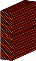
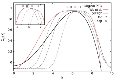
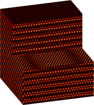
The issue of defect stability and its reliance on the correlation kernel can be illustrated with an analysis of the fcc intrinsic stacking fault energy ( or SFE) and stability as a function of the number of fcc reflections considered in . The full CDFT of Eq. (1) with given by Eq. (6) was employed, as discussed below. Faulted crystals were evaluated within a periodic simulation cell with axes in directions, and a single intrinsic stacking fault was created by removing one close-packed layer and shifting the layers above down by , where is the equilibrium fcc lattice constant. The final number of close-packed layers must satisfy , where is an integer ( was used in most cases here). Initial states were relaxed using Eq. (5). In this geometry, the stacking fault may be stable, metastable, or unstable, with instability unfolding through a shearing operation or that removes the stacking fault and creates a uniformly sheared perfect crystal with total shear strain , as shown in Fig. 1.
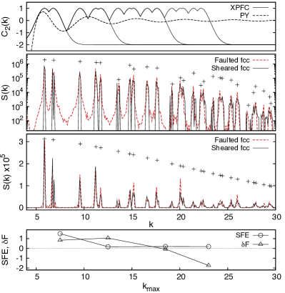
Some results are displayed in Fig. 2 along with specific parameter values employed. Stacking faults were found to be highly unstable in the two-peaked model for virtually all meaningful values of (). With five peaks, metastable faults were observed, while ten peaks produced fully stable faults for which the energy of the faulted crystal was very slightly lower than that of the sheared state (). A 15 peak model was also found to be fully stable against shear, with a larger negative . The relevant structure factors for the 15 peak model are shown in Fig. 2. These results indicate that the stability of stacking faults to shear increases as larger- correlations are considered. The reason for this behavior is discussed later in this section.
Significantly, the computational efficiency of these models decreases rapidly with increasing . The amplitude of the density peaks must be allowed to grow roughly as if the larger- modes are to contribute significantly to the free energy of the system. This necessitates use of the full logarithmic one-body term in the free energy, without expansion, since the truncated expansion of Eq. (2) limits stable amplitudes to relatively small values, . The logarithm greatly reduces the maximum allowable time step, while the higher- modes reduce the density peak width (as shown in Fig. 2, top) and therefore the maximum allowable grid spacing .
II.1.2 Many-peaked CDFT model
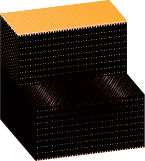
A similar analysis was attempted using the full RY CDFT of Eq. (1), with given by the Percus-Yevick (PY) expression for hard spheres Percus and Yevick (1958); Wertheim (1963) and dynamics given by Eq. (5). Our findings indicate that hcp crystals in this model actually tend to have a slightly lower free energy than fcc crystals, a fact that apparently has not been appreciated before. This leads to a negative and therefore stacking faults that are inherently stable to the sheared state. Nonetheless, a perfect edge dislocation in a metastable fcc crystal was found to split into two well-separated Shockley partial dislocations connected by a stacking fault, as expected for low materials (Fig. 3). The reaction is
| (7) |
Though both and in this system are always negative or very small and positive, making instability to shear virtually impossible, we did find that increases as is reduced. This was determined by modifying the PY function as for , while holding constant. The observed trend in indicates that the underlying link between stability and found in the XPFC model is also present here.
II.1.3 Analysis and generalization
This link can be understood by examining the spectra of the two relevant states, the faulted crystal and the sheared/unfaulted crystal (see Fig. 2). An infinite stacking fault can be expressed mathematically as a 1D step function in the 3D displacement field of the crystal, with the step direction normal to the fault. The structure factor of a faulted crystal therefore contains the same line-shapes characteristic of scattering from a surface. In this case each lattice reflection , except the set of planes parallel to the stacking fault, will possess its own set of modes, and these modes will only extend in the reciprocal space direction perpendicular to the plane of the fault, . The spherically averaged structure factor thus exhibits a sequence of broadened fcc reflections, each with effective line-shapes of roughly the same width foot2 (2012).
The structure factor of a sheared perfect crystal also exhibits a form of peak broadening, but in this case the degree of broadening is proportional to . Depending on the orientation of shear strain , or deformation in general, the spacing between certain lattice planes within any given family changes to some value . A simple analysis shows that the resulting shift in -space under shear is
| (8) |
where . Thus the primary low- reflections remain sharp and/or slightly split, while the degree of shift or effective broadening increases in proportion to due to this growing decoherence effect across high-index, low- planes.
The driving force for stacking fault instability is primarily a function of . When a low-mode kernel is used, will tend to be smaller than because the slightly shifted low- modes of a sheared crystal induce a small energy cost relative to that of the long-range line-shape tails of a faulted crystal, provided that the shear strain is not too large. As increases, this situation eventually reverses. The high order reflections from the sheared lattice become broader or less coherent than those of the faulted crystal such that if enough high- modes are considered, stacking fault stability can eventually be attained when . This effect can be seen in the data of Fig. 2. We emphasize that the high- modes do not necessarily decrease or , but that the increase in alone leads to a dramatic increase stacking fault stability. In the geometry of our simulations, the critical wavenumber at which increases with since , but for fixed stability increases with . The exact wavenumber at which stability is attained ( in this case) also depends on model parameters, but the basic trends should generally hold.
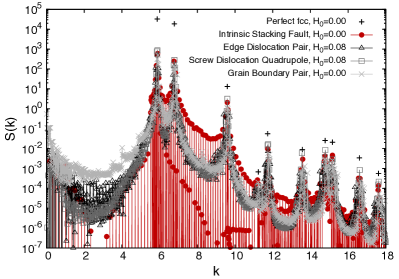
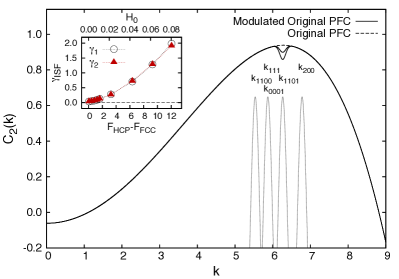
Similar arguments can be constructed for other types of defects by reconsidering for each case the two generic parameters controlling stability, driving force and energy barrier. The driving force for instability is controlled by both the energy of the defected state and the energies of the states resulting from defect removal. In the case just examined, this force was quantified by , the energy difference between the faulted state and the competing sheared state. The magnitude of this force is therefore deeply tied to the precise form of and the energy cost that it imposes on defect line-shapes, a few examples of which are shown in Fig. 4. These spectra were obtained using the modulated version of the original PFC model presented in Section III.1, though the basic features do not depend on the model used. The four crystals shown have roughly equivalent defect densities and their structure factors exhibit similar line-shapes, with the stacking fault producing the greatest degree of broadening. It is apparent that in general, broad correlation kernels will reduce the energies of all of these defect structures and therefore the driving force for their instability, as demonstrated explicitly in the next subsection. Alternatively, stacking faults were stabilized in the previous example by instead increasing the energy of the post-defect-removal sheared state through high- correlation effects. This simply illustrates that the driving force can be controlled by varying the energy of the initial state, the final state, or both through the form of .
The second parameter relevant to stability, the energy barrier for defect removal or topological protection, is controlled by the nature of the process by which a given defect can be removed. The shearing operation that removes a stacking fault requires only small local translations of the density peaks. No peaks are created or removed, thus no long-range mass transport is involved, and the resulting energy barrier is small. Stability in such a case therefore requires that the driving force be minimized, since the energy barrier is in general more difficult to manipulate. Removal of dislocations and grain boundaries on the other hand requires more elaborate transformations that often involve climb, with redistribution of atoms by long-range diffusive mass transport (adding or removing density peaks in the case of a PFC model). These defects thus have greater inherent stability than stacking faults due to both their somewhat narrower line-shapes and their generally larger energy barriers for removal foot3 (2012).
The results presented in this section demonstrate that certain defect structures can be stabilized in PFC models by building structural information back into the model with additional correlation peaks. The resulting multi-peaked models require the full logarithmic free energy functional and therefore suffer from marked inefficiencies and greater complexity relative to existing PFC models studied in the literature. However, the sources of defect instability uncovered here will prove useful in analyzing and constructing few-peaked PFC models that both retain efficiency and stabilize relevant defects.
II.2 Small wavenumber or low-mode models
The inefficiencies associated with large wavenumber models can be avoided by maintaining the small wavenumber PFC approximation and giving closer treatment to the details of the one or few correlation peaks employed. We have successfully stabilized stacking faults using four variations of PFC with the small wavenumber approximation, though in general this requires some degree of parameter tuning and/or slight modification of .
Perhaps the simplest way to improve defect stability in this approximation is to use a broad in the region of the first few primary lattice reflections. This in general lowers the energy associated with defect line-shapes while having little to no effect on the energy of, for example, uniformly sheared states or undeformed crystals. A sufficiently broad envelope can thus stabilize the stacking fault modes relative to the first few sheared state shifts. The main drawback is that the stability of the equilibrium crystal structure tends to decrease as is broadened. For example, a two-peaked XPFC fcc model can prefer hcp, bcc, rod, or lamellar structures over fcc for sufficiently large . Thus defect stability is not given freely, it comes inversely bound to crystal stability. This trade-off must be managed by ensuring that the primary reflections of the desired crystal structure continue to be preferred over those of competing symmetries that may exist within a broad envelope. Specific parameter values related to the width of (elastic moduli) therefore become restricted, but a workable balance between defect stability and crystal stability is still often attainable in the small wavenumber PFC approximation, as demonstrated in the following subsections.
II.2.1 Original PFC model
We begin with the original PFC model of Elder et al. Elder et al. (2002); Elder and Grant (2004), for which the correlation kernel and the primary fcc and hcp reflections are shown in Fig. 5. This PFC or Brazovskii Brazovskii (1975) functional specifies a kernel
| (9) |
where is a constant proportional to the solid-phase elastic moduli and . This produces equilibrium fcc structures within a certain parameter range Jaatinen and Ala-Nissila (2010); Tóth et al. (2010), but the energy of the hcp crystal is necessarily always very close to that of fcc, and is sometimes lower. This means that the fcc is always vanishingly small in the original PFC model, which naturally stabilizes stacking faults relative to shear. Perfect dislocations, as with the CDFT hard-sphere model, split into two well-separated Shockley partials and a stacking fault, as shown in Fig. 6. Note that, for display purposes, the defects shown in Fig. 6 were generated using a modified version of Eq. (9), discussed in Section III.1. The small value of produced by Eq. (9) leads to an equilibrium splitting distance for edge dislocations, which is significantly larger than values observed in typical single component fcc metals.
The broad function of the original PFC model therefore naturally stabilizes defects, but is relatively limited in terms of flexibility in controlling crystal symmetry and elastic properties. One is restricted to the deep quench region of fcc stability, where small changes to the elasticity parameter tend to destabilize fcc, and the inherent is extremely small. It is possible to tune within a small range by varying the envelope width , but a more effective approach is to explicitly enhance or suppress specific hcp and fcc modes, as demonstrated in Section III.
II.2.2 Low-mode XPFC model
XPFC models with only a few low- peaks can also be tuned to support less protected defect structures, though some modifications seem to be necessary in the case of fcc stacking faults. As is increased above or , Gaussian kernel peaks generally become too broad to maintain a consistent crystal structure before they are broad enough near their maxima to sufficiently support the stacking fault modes. We have obtained better results in this regard using a modified Gaussian shape function,
| (10) |
where the coefficients set the relative weight of versus shape functions. This formulation still permits control of the phase diagram in the original spirit of the model as well as the magnitude and anisotropy of elastic constants, though the range of parameter values sufficient for stability remains restricted. Values in the vicinity of , , , , , , and have been found sufficient to stabilize stacking faults in a three-peaked fcc model with two fcc reflections at and one commensurate hcp reflection at (see Fig. 5). Similar results have been obtained using only the two fcc reflections with their maxima connected by any nearly linear bridge function.
These findings highlight the conflict between crystal stability and defect stability in small wavenumber models. Very narrow crystal-stabilizing XPFC kernels destabilize defects of all but the most protected types, somewhat broader kernels still tend to destabilize susceptible planar fault structures, while very broad fully defect-stabilizing XPFC kernels ultimately resemble the simpler kernels of the original PFC model. These inherent trade-offs suggest a limitation to the range of atomic-level crystal and defect structures that low-mode, two-body PFC models can capture, though the ultimate limit apparently lies at some level of complexity beyond that of the primary defect structures in fcc crystals.
II.2.3 Wu et al. fcc PFC model
The two-mode fcc model introduced by Wu et al. Wu et al. (2010) also produces stable stacking faults within certain parameter ranges. To facilitate tuning of and stability, we find it helpful to retain a bulk modulus coefficient analogous to that of the original PFC kernel,
| (11) |
where is the wavenumber of the second mode and sets its height. We find that quenches of intermediate depth tend to produce fcc crystals with moderate , and that decreases with increasing . This is because the energy of hcp approaches and may become lower than that of fcc as the quench becomes deeper. As an example, the parameter set , , , and produces metastable stacking faults for and perfect dislocations that do not split into partials. As is lowered, stacking faults eventually become fully stable, with producing a very low and widely split partial dislocations (see Fig. 5). also varies rapidly with , again permitting only a small degree of elastic moduli tuning.
The source of defect stability in this PFC model is apparent from examination of the kernel around the primary fcc modes. Elasticity parameters produce broad profiles with very shallow wells between to the two modes, while produces narrowing profiles with increasingly deeper wells. Using the parameter values above at and , the stacking fault line-shapes are already unfavorable enough to fully destabilize faulted crystals. This two-mode model comes with similar restrictions in terms of acceptable parameter ranges to those of the original and XPFC models, but does provide greater control of fcc stability than the original PFC model, allowing use of shallower quenches closer to the linear elastic regime.
II.2.4 Vacancy PFC model
The vacancy PFC or VPFC model typically employs the same as the original PFC model, but adds a strong local nonlinear cutoff term that destroys the inherent one-mode nature of inhomogeneous density states and produces relatively autonomous individual density peaks separated by regions of zero density Chan et al. (2009); Berry and Grant (2011). This can lead to stabilization of individual lattice vacancies and in general produces a Brownian hard-sphere-like system in which fcc and hcp structures have lowest free energy, with a slight preference toward fcc. When vacancies are stabilized in this way, packing effects become more important and the natural similarities between fcc and hcp in this regard should lead to low systems. We find that a low , comparable to that of the original PFC kernel, is indeed obtained with the VPFC description, though in this case we attribute the low value primarily to entropic or packing effects. In this sense, the VPFC model is likely the most defect-friendly of existing PFC models, but one must reinterpret the time scales accessible to this description since the explicit vacancy diffusion mechanism has been partially reintroduced. Nonetheless, stacking faults are quite stable in this formulation and perfect dislocations split properly into partials joined by a stacking fault.
III Survey of fcc Defect Properties in a Small Wavenumber PFC Model
The findings presented in Section II suggest that many types of crystalline defects observed in real materials, even those with relatively low inherent stability, can be stabilized within existing PFC models. The general requirement for stability under the small wavenumber approximation involves a sufficiently broad correlation kernel maximum, which leads to restrictions on the parameter ranges that provide both defect and crystal stability. Nonetheless, these restrictions appear to be manageable in the case of close-packed crystals, and closer examinations of fcc systems reveal that a wide variety of realistic defect properties naturally emerge within these parameter ranges. Some of these properties are discussed in the present section.
Emphasis is placed on fcc crystals and tuning of the stacking fault energy to generate either undissociated perfect dislocations (high ) or dissociated Shockley partial dislocations bound by stacking faults (low ). Various fundamental properties of both edge and screw dislocations in these configurations are examined.
III.1 Modulation of the original PFC model
As discussed in Section II.2.1, the dissociation width of a perfect dislocation in the original PFC model is larger than that of most single component fcc metals, due to the small value of relative to the fcc elastic moduli. This behavior can be tuned by various means. Since is strongly linked to the difference in free energy between commensurate fcc and hcp states, one method to control is to selectively promote or suppress the primary hcp reflections that do not coincide with those of the fcc crystal. For example, the commensurate hcp reflection at can be suppressed by subtracting a small XPFC-type Gaussian centered at this wavenumber from the of Eq. (9), such that the two fcc reflections are not affected,
| (12) |
The constants and are analogous to those of Eq. (6).
The original PFC kernel modified in this way is shown in Fig. 7. The result is greater stabilization of fcc due to the increase in , and a corresponding increase in as the height of the subtracted Gaussian becomes larger. This is similar to that of Wu et al. with variable , though some subtle differences are apparent. Only of the equilibrium fcc state changes as is varied, producing an essentially fixed reference system with tunable . The standard phase diagram is of course modified for nonzero , proportionally expanding the region of fcc stability. The dependence of on is also shown in Fig. 7. faults are stable or metastable for , and very little system size dependence is observed in for .
III.2 Dissociation width vs.
This method of controlling can be used to examine defect properties that depend on stacking fault energy, and to compare functional dependencies with those predicted by continuum elastic theories. For example, the elastic strain energy of a fcc crystal containing a perfect dislocation with is lowered by dissociation into two Shockley partials with and a stacking fault, as described by Eq. (7). This is confirmed by the Frank criterion, . Continuum elastic theories provide predictions for the equilibrium separation between the two resultant Shockley partials. The long-range elastic energies of the partials produce a repulsive force per length of dislocation line proportional to , while the energy cost of the fault increases with , producing an attractive force per length proportional to . The separation that balances these two forces for an elastically isotropic material is given by Hirth and Lothe (1982)
| (13) |
where is the Poisson ratio, is the angle between the Burgers vector of the perfect dislocation and its line direction, and is the isotropic shear modulus of the crystal. Similar though more complicated results can be derived using anisotropic elasticity or various approximations thereof Hirth and Lothe (1982).
We have measured for both edge and screw dislocations in the modulated PFC model, as a function of . Base parameter values , , and were used, giving an fcc lattice constant . The crystal orientation of Section II was employed (see Fig. 6), though in this case with periodicity broken in the -direction by a thin layer of liquid. A single perfect edge dislocation with line direction was initialized at using system dimensions and (203,668 atoms). Perfect screw dislocation dipoles with line directions were initialized similarly at and with and (107,692 atoms). The symmetry of the screw dislocation displacement field in the -direction necessitates a dipole configuration. In both cases the diffusive dynamics of Eq. (3) were used. Results are shown in Fig. 8, including comparisons with Eq. (13) and the available anisotropic theories.
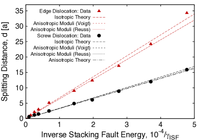
The expected linear trend is clearly observed for both dislocation types, and the agreement with linear elastic predictions is excellent. The fully isotropic theory very slightly overestimates , while the isotropic theories with approximate anisotropic moduli of Voigt and Reuss Hirth and Lothe (1982) and the fully anisotropic theory (which is tractable only for the screw dislocation) match the data extremely well foot4 (2012). We note that it was necessary to simulate relatively large systems to eliminate significant boundary and image effects. The periodic image forces nonetheless induce a small bias toward larger that grows with and appears to become appreciable for at this system size. Otherwise, the largest proportional disagreement is seen at small values of where the linear elastic predictions are likely somewhat inaccurate due to core overlap effects. We believe that these results provide an important validation of fundamental defect energetics and interactions within the PFC description.
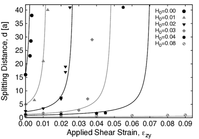
III.3 Dissociation width vs. applied (Escaig) strain
When the glide-inducing shear strain is applied to either of the dissociated dislocation lines shown in Fig. 6, the two partials will glide together with a nearly constant separation (except at large velocities as discussed below). This is because the components of their respective Burgers vectors in the shear direction have the same sense. This is not the case for shear strain . The two partials have components in this shear direction with opposite sense, which produces glide forces in opposite directions that extend the faulted region in between. This particular strain orientation is sometimes referred to as the Escaig strain. The new equilibrium separation for fixed stress can again be calculated within isotropic elasticity theory, and for a general dislocation one obtains Byun (2003)
| (14) |
where , and , are the angles between the overall dislocation line direction and the Burgers vector directions of the leading and trailing partials, respectively. For the case of a screw dislocation, where and , Eq. (14) reduces to
| (15) |
Shear strain was applied to the screw dipole configurations described in the previous subsection by adding a penalty function to the first few crystalline surface layers near the liquid boundaries and translating the penalty field at some constant rate to drive the external deformation. An affine shear deformation was also applied to the entire crystal at each time step, and the inertial equation of motion, Eq. (4), with and was used. These features together should ensure that the resolved shear strain at the dislocation remains as close to the applied shear strain as possible. Selected fixed values of were held periodically to allow the system to fully relax to a steady configuration. Though a reliable method of directly quantifying stress in our simulations is currently lacking, the assumption of linear elasticity will produce accurate stress-strain conversions whenever plastic flow / stress dissipation is negligible and strain is not exceedingly large. We can confidently apply this assumption here () to obtain results in terms of stress, which can be directly compared with Eq. (15). Expected errors are for .
Simulation results are compared with the predictions of Eq. (15) in Fig. 9. The lines show Eq. (15) with elastic parameters as determined from simulations. The agreement is in general good for all values of , with the expected trend of diverging separation clearly visible. The strain at which divergence appears to occur agrees well with the predictions for small , though not surprisingly shows increasing deviation as and become large. These findings demonstrate that non-trivial defect properties associated with interactions between defects and applied stresses can be accurately modeled with this approach.
III.4 Peierls stress/strain for dislocation glide
Dislocation motion is the dominant microscopic element of plastic deformation in most crystalline and polycrystalline metals. The minimum strain required to move a dislocation, the Peierls strain , is therefore a fundamental material property that can qualitatively alter a material’s macroscopic plastic response, yield stress, etc. fcc metals, in which dissociated dislocations and stacking faults are prevalent, typically exhibit a characteristic slip activity that derives directly from the nature of the dissociated dislocation structure and the anisotropy of its Peierls barrier. Stacking faults are stable only on planes, and the Peierls barrier for motion of the partials is normally very small or negligible within the same slip planes. The result is that a large majority of slip activity occurs only within planes, and a regime of qualitatively different plastic response emerges when cross-slip between planes becomes active. Thus a faithful description of the underlying Peierls barrier is central to any model of crystal plasticity, and will naturally give rise to many of the secondary features and processes that emerge from the fundamental mechanism.
Accurate measures of Peierls stresses in fcc metals have proven difficult to obtain through atomistic computations, due to the smallness of relative to typical boundary image stresses in finite size simulations Olmsted et al. (2001). Typical estimates thus vary greatly in the literature, but the most reliable values measured from molecular dynamics (MD) simulations are believed to be on the order of - for fcc edge dislocations and - for fcc screw dislocations Olmsted et al. (2001); Hirth and Lothe (1982); Duesbery (1998). Experimentally determined values also vary greatly, from , depending on the method employed Basinski (1959); Bujard et al. (1987); Nabarro (1997). Nonetheless, within these general ranges, screw lines are expected to have larger barriers than edge lines, and unsplit perfect dislocations to have larger barriers than split partial configurations.
The Peierls strains for glide of edge and screw dislocations, dissociated and undissociated, were measured by applying shear to each system as described in the previous subsection. Eq. (4) with and was again employed, though in this case shear strain was applied. This orientation, unlike , produces uniform glide of both dislocation types, with split partials gliding in the same direction. was defined as the magnitude of applied strain at the instant a given defect has glided a distance equal to its Burgers vector magnitude .
The simulation results shown in Fig. 10 bear out all of the expectations noted above with only relatively minor quantitative deviations. All dislocations exhibit the same roughly barrier strain dependence for sufficiently large shear rates. The cause of this behavior is discussed below, but our primary interest is in the limiting values obtained at small shear rates. Since the amount of dislocation motion in these simulations is negligible, we can again apply linear stress-strain relations to report Peierls stresses rather than strains (). The unsplit screw Peierls stress approaches a value within the expected range , while the average Peierls stress for the split screw is slightly lower, . The measured values for the leading and trailing screw partials differ by a small amount. This may be a consequence of weakly asymmetric periodic image forces generated by the simulation boundaries, or of an initial value that is incommensurate with the periodicity of the Peierls potential, as discussed in Ref. Nabarro, 1997.

The widely split edge dislocation exhibits much less deviation between leading and trailing values, though the apparent limiting value is not smaller than that of the perfect edge dislocation to within expected error. Both configurations approach a value that appears to extrapolate to , also within the expected range for typical fcc edge dislocations. It was observed that edge dislocations tend to glide with a relatively uniform, continuous progression, while screws exhibit a more pronounced stick-slip hopping motion with each unit of translation, indicative of a larger Peierls barrier. These results together demonstrate that the fundamental features of fcc Peierls stresses are captured quite reasonably by this relatively simple PFC model.
The apparent relation for larger shear rates can be obtained as follows. Based on our results, there appears to be an intrinsic time scale associated with relaxation of an entire defect structure, inluding the core region and the long-range displacement fields. If shear is applied slowly relative to , the core region and the long-range displacements can evolve cooperatively such that the inherent Peierls barrier of the given dislocated system, , is realized. If is large relative to , then the short-range and long-range components cannot relax with optimal synchronization. This introduces nonequilibrium effects and alternate relaxation processes that lead to measurement of some larger effective barrier .
In the PFC formulation, slow relaxations near equilibrium are diffusive whether one uses Eq. (3) or Eq. (4). Thus the intrinsic defect time scale can be approximated as an exponential relaxation time, and neglecting other relaxations, should be, to a first approximation, an exponential function of the dimensionless parameter . We therefore may write or in the small limit. Combining this relation with a linear elastic response, , we obtain where is a constant. This form and the corresponding unexpanded form both fit our results well, indicating that the competition between rate of applied shear and rate of diffusive strain field relaxation leads to an increased effective Peierls strain with relevant control parameter . The observed system size dependence of is also consistent with this expression.
III.5 Dynamic contraction of dissociated dislocations
When the glide-inducing stress is applied to a dissociated dislocation, the Peierls barrier is overcome quite quickly and glide is initiated within the slip system of the defect. The structure of the extended defect may then be altered by dynamic effects associated with navigation of the Peierls potential as well as drag or damping forces of various origins. Employing the dynamics of Eq. (4), we applied fixed shear strain rates to the dissociated edge and screw dislocation configurations already described, and allowed each to approach a steady-state glide velocity , while montoring the separation between paired partials . Similar results were obtained for both dislocation types, and those for the edge dislocation are shown in Fig. 11. For relatively low steady-state velocities (), was found to exhibit regular oscillations in time. These oscillations, which can be seen in the lowest shear rate data displayed in Fig. 11, are not unlike the so-called breathing modes observed in MD simulations Mordehai et al. (2003, 2006), though their period appears to be significantly longer and more regular in these PFC simulations.
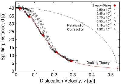
At higher velocities a dramatic decrease in was observed, followed by a return approximately to the initial upon release of strain. Since the shear strain does not significantly alter or the repulsive force between static paired partials, this contraction appears to be a fully dynamic effect. We believe that the primary mechanism at work is a difference in the frictional drag force experienced by each partial at high PFC velocities or, similarly, a reduction of the drag force exerted on the extended defect structure as a whole. Either scenario may result from the difference in screw-edge character between the two partials Hirth and Lothe (1982) or may be driven by a cooperative drag-reduction process analogous to the phenomenon of drafting or slipstreaming in fluid dynamics.
At low velocities, where the effect of drag is small, is determined primarily by the height of successive barriers in the Peierls potential. Thus any forces that might change the dissociation width are small, though they may become large enough to generate low-amplitude breathing modes. As increases, the Peierls potential becomes less relevant and the effect of frictional drag becomes large. In this regime, a dissociated defect may experience a larger total drag force than an undissociated one due to its greater extension. The total drag force may be reduced, thus increasing at a given strain, by reducing such that the trailing partial assumes an optimized lower-drag position within the leading wake or slipstream. At large enough velocities, the reduction in drag force experienced by the full defect under contraction may compensate for the increase in local defect energy. The energy of the entire system is reduced by the excess strain relief that is a consequence of faster dislocation glide.
We can modify the analysis given in Ref. Hirth and Lothe, 1982 to incorporate such an effect into the predicted steady-state value of . The steady-state force balance between gliding paired partials can be writtenHirth and Lothe (1982)
| (16) |
where is an abbreviation of the terms multiplying in Eq. (13), and are the forces per unit length on and , respectively, due to the applied shear, and and are the damping forces per unit length on the moving partials. First we assume that both partials experience the same force due to the applied shear strain () and that the nominal drag force on each PFC dislocation obeys a Stokes’ law form (), as shown in Ref. Berry et al., 2006. The drag coefficient should roughly be given by , where is the partial dislocation mobility. Finally, since we assume that decreases with () a plausible functional form for must be proposed. We will use where , and , are constants.
A fit to the resulting equation for vs. is shown in Fig. 11. The only adjustable parameters in the fit are and , and the agreement is very good. Semi-relativistic contraction of strain fields in the glide direction has also been predicted for dislocations moving at velocities near the sound speed of the crystal Hirth and Lothe (1982). A curve illustrating this effect is shown in Fig. 11, where it is assumed that both partials experience the same contraction effect and reduce accordingly. This mechanism does not have a large effect until the sound speed is approached and its form is not consistent with our results. Furthermore, we observe similar behavior to that shown in Fig. 11 when dynamics are given by Eq. (3), which does not introduce a sound speed.
The PFC description is generally best suited for examining behavior under relatively low strain rates or driving forces, where dislocation velocities tend not to closely approach the sound speed. Nonetheless, a better understanding of the nature of the interaction between moving dislocations and the quasi-phonons described by Eq. (4) would be useful in terms of confirming that the artificially low sound speeds employed in PFC simulations do not qualitatively alter the low and intermediate velocity dislocation dynamics. Details of these issues are deferred to a future publication.
IV Discussion and Conclusions
The primary factors controlling defect stability in PFC models have been examined, and it has been demonstrated that broad correlation kernels or elastically soft crystals produce the greatest defect stability. Maximally broadened kernels appear to be necessary for stabilization of certain defects such as planar faults in the small wavenumber PFC approximation. Higher wavenumber correlations with narrower peaks were also shown to improve stability in some cases, but this feature leads to greatly reduced model efficiency. The inherent conflict between crystal stability and defect stability in broad kernel models suggests potential limitations to the complexity of structures that can be described by such models. Any such limitations were shown to be non-factors in the case of the primary defect structures in close-packed fcc crystals.
Stacking faults with low inherent stability were stabilized in four PFC variants, indicating that considerable defect stability can be obtained without losing crystal stability. The central defect structure in fcc plasticity, dissociated partial dislocations with stacking faults, has been examined in some detail and shown to be well-described by PFC methods. The dependence of the equilibrium dissociation width on stacking fault energy has been shown to agree with continuum elastic predictions for both edge and screw dislocations, under zero and nonzero applied external stresses. Peierls stresses for glide of both dislocation types have also been measured and shown to fall within the typical ranges and relative magnitudes determined from experiments and MD simulations. Contraction of gliding pairs of partials has been observed at high velocities and argued to be a consequence of large frictional drag forces on widely split partials.
The findings presented in this article are intended to lay the groundwork for larger-scale PFC studies of plasticity in fcc crystals, with the potential to examine experimentally relevant strain rates, nonconservative/climb-driven defect evolution, and processes in which diffusing solute atoms interact with mobile and/or immobile defect structures. These, in practice, are inaccessible to conventional MD simulations. Conversely, PFC models cannot reliably access the rapid time scales of MD and likely cannot predict some details of more complex defect atomic core structures as accurately as MD. Microscopic phase field (MPF) models of defects Wang and Li (2010) are related to PFC in the sense that both employ phase field methodologies, but MPF models utilize a top-down approach, explicitly building the defect physics in by hand. PFC models employ a far simpler, atomic-level free energy functional, from which all defect physics automatically emerge with fewer imposed constraints and with straightforward dynamical extensions. Nonetheless, by directly incorporating ab initio data such as -surface energies Shen and Wang (2004); Hunter et al. (2011), MPF models have proven highly effective in terms of predicting static core-level defect structures and energies with greater quantitative accuracy than current PFC descriptions. At a more coarse-grained level, both discrete dislocation dynamics models Groh and Zbib (2009) and coarse-grained phase field dislocation dynamics models Wang and Li (2010) readily describe length scales inaccessible to MD, MPF, and PFC. Similarly large length scales are in principle also accessible to coarse-grained complex amplitude representations of PFC models Goldenfeld et al. (2005); Athreya et al. (2007); Yeon et al. (2010); Huang et al. (2010); Spatschek and Karma (2010), which still retain atomistic resolution.
Targeted PFC studies, examining more complex problems in defect physics that involve atomic length scales and diffusive time scales, will be the subject of an upcoming publication. Topics that have been analyzed and will be addressed include climb fundamentals, the structure of jogged dislocation lines, jog constriction, jog pair annihilation, jog drag, screw dislocation cross-slip, formation and collapse of stacking fault tetrahedra from triangular Frank vacancy loops, Lomer-Cottrell or stair-rod dislocations, the interaction of dissociated edge and screw dislocations with stacking fault tetrahedra, and dislocation creation mechanisms.
Acknowledgements.
This work has been supported by the Natural Science and Engineering Research Council of Canada (NSERC), and access to supercomputing resources has been provided by CLUMEQ/Compute Canada.References
- Elder et al. (2002) K. R. Elder, M. Katakowski, M. Haataja, and M. Grant, Phys. Rev. Lett. 88, 245701 (2002).
- Elder and Grant (2004) K. R. Elder and M. Grant, Phys. Rev. E 70, 051605 (2004).
- Elder et al. (2007) K. R. Elder, N. Provatas, J. Berry, P. Stefanovic, and M. Grant, Phys. Rev. B 75, 064107 (2007).
- Goldenfeld et al. (2005) N. Goldenfeld, B. P. Athreya, and J. A. Dantzig, Phys. Rev. E 72, 020601 (2005).
- Athreya et al. (2007) B. P. Athreya, N. Goldenfeld, J. A. Dantzig, M. Greenwood, and N. Provatas, Phys. Rev. E 76, 056706 (2007).
- Yeon et al. (2010) D. Yeon, Z. Huang, K. R. Elder, and K. Thornton, Philos. Mag. 90, 237 (2010).
- Huang et al. (2010) Z.-F. Huang, K. R. Elder, and N. Provatas, Phys. Rev. E 82, 021605 (2010).
- Spatschek and Karma (2010) R. Spatschek and A. Karma, Phys. Rev. B 81, 214201 (2010).
- Berry et al. (2006) J. Berry, M. Grant, and K. R. Elder, Phys. Rev. E 73, 031609 (2006).
- Stefanovic et al. (2006) P. Stefanovic, M. Haataja, and N. Provatas, Phys. Rev. Lett. 96, 225504 (2006).
- Stefanovic et al. (2009) P. Stefanovic, M. Haataja, and N. Provatas, Phys. Rev. E 80, 046107 (2009).
- Hirouchi et al. (2009) T. Hirouchi, T. Takaki, and Y. Tomita, Comp. Mat. Sci. 44, 1192 (2009).
- Chan et al. (2010) P. Y. Chan, G. Tsekenis, J. Dantzig, K. A. Dahmen, and N. Goldenfeld, Phys. Rev. Lett. 105, 015502 (2010).
- Jaatinen et al. (2009) A. Jaatinen, C. V. Achim, K. R. Elder, and T. Ala-Nissila, Phys. Rev. E 80, 031602 (2009).
- Backofen et al. (2010) R. Backofen, A. Voigt, and T. Witkowski, Phys. Rev. E 81, 025701(R) (2010).
- Jaatinen et al. (2010) A. Jaatinen, C. V. Achim, K. R. Elder, and T. Ala-Nissila, Technische Mechanik 30, 169 (2010).
- Berry et al. (2008) J. Berry, K. R. Elder, and M. Grant, Phys. Rev. B 77, 224114 (2008).
- Mellenthin et al. (2008) J. Mellenthin, A. Karma, and M. Plapp, Phys. Rev. B 78, 184110 (2008).
- Olmsted et al. (2011) D. L. Olmsted, D. Buta, A. Adland, S. M. Foiles, M. Asta, and A. Karma, Phys. Rev. Lett. 106, 046101 (2011).
- Singh (1991) Y. Singh, Phys. Rep. 207, 351 (1991).
- Oxtoby (2002) D. Oxtoby, Annu. Rev. Mater. Res. 32, 39 (2002).
- Ramakrishnan and Yussouff (1979) T. V. Ramakrishnan and M. Yussouff, Phys. Rev. B 19, 2775 (1979).
- foot1 (2012) The latter implies that the Fourier transformed kernel is effectively shifted by a constant relative to the kernel defined in Eq. (1). To maintain consistency with existing notation we will neglect this constant, and it will be implied that must be subtracted from all kernels associated with Eq. (2) if one wishes to recover the kernel that is fully consistent with Eq. (1).
- Dasgupta (1992) C. Dasgupta, Europhys. Lett. 20, 131 (1992).
- Greenwood et al. (2010) M. Greenwood, N. Provatas, and J. Rottler, Phys. Rev. Lett. 105, 045702 (2010).
- Greenwood et al. (2011a) M. Greenwood, J. Rottler, and N. Provatas, Phys. Rev. E 83, 031601 (2011a).
- Greenwood et al. (2011b) M. Greenwood, N. Ofori-Opoku, J. Rottler, and N. Provatas, Phys. Rev. B 84, 064104 (2011b).
- Percus and Yevick (1958) J. K. Percus and G. J. Yevick, Phys. Rev. 110, 1 (1958).
- Wertheim (1963) M. S. Wertheim, Phys. Rev. Lett. 10, 321 (1963).
- foot2 (2012) The reflection will be broadened as well because the three additional planes that are not parallel to the fault will contain modes.
- foot3 (2012) Depending on local defect configurations some dislocation and grain boundary structures can annihilate by glide alone, leading to much lower energy barriers for removal. This effect is naturally captured by CDFT and PFC descriptions.
- Brazovskii (1975) S. A. Brazovskii, Sov. Phys.-JETP 41, 85 (1975).
- Jaatinen and Ala-Nissila (2010) A. Jaatinen and T. Ala-Nissila, J. Phys.: Condens. Matter 22, 205402 (2010).
- Tóth et al. (2010) G. I. Tóth, G. Tegze, T. Pusztai, G. Tóth, and L. Gránásy, J. Phys.: Condens. Matter 22, 364101 (2010).
- Wu et al. (2010) K.-A. Wu, A. Adland, and A. Karma, Phys. Rev. E 81, 061601 (2010).
- Chan et al. (2009) P. Y. Chan, N. Goldenfeld, and J. Dantzig, Phys. Rev. E 79, 035701(R) (2009).
- Berry and Grant (2011) J. Berry and M. Grant, Phys. Rev. Lett. 106, 175702 (2011).
- Hirth and Lothe (1982) J. P. Hirth and J. Lothe, Theory of Dislocations (John Wiley & Sons, Inc., 1982), 2nd ed.
- foot4 (2012) The independent elastic constants were measured numerically by using Eq. (3) and applying the appropriate strains, giving , , and . An isotropic approximation of Poisson’s ratio is therefore , and the anisotropy ratio is . Thus there is a small degree of elastic anisotropy in this system, as evidenced by the slightly lower slopes for the anisotropic predictions in Fig. 8. The expressions for the Voigt and Reuss average anisotropic moduli can be found in Ref. Hirth and Lothe, 1982.
- Byun (2003) T. Byun, Acta Materialia 51, 3063 (2003).
- Olmsted et al. (2001) D. L. Olmsted, K. Y. Hardikar, and R. Phillips, Modelling and Simulation in Materials Science and Engineering 9, 215 (2001).
- Duesbery (1998) M. S. Duesbery, Modelling and Simulation in Materials Science and Engineering 6, 35 (1998).
- Basinski (1959) Z. S. Basinski, Phil. Mag. 4, 393 (1959).
- Bujard et al. (1987) M. Bujard, G. Gremaud, and W. Benoit, J. Appl. Phys. 62, 3173 (1987).
- Nabarro (1997) F. R. N. Nabarro, Phil. Mag. A 75, 703 (1997).
- Mordehai et al. (2003) D. Mordehai, Y. Ashkenazy, I. Kelson, and G. Makov, Phys. Rev. B 67, 024112 (2003).
- Mordehai et al. (2006) D. Mordehai, I. Kelson, and G. Makov, Phys. Rev. B 74, 184115 (2006).
- Wang and Li (2010) Y. Wang and J. Li, Acta Materialia 58, 1212 (2010).
- Shen and Wang (2004) C. Shen and Y. Wang, Acta Materialia 52, 683 (2004).
- Hunter et al. (2011) A. Hunter, I. J. Beyerlein, T. C. Germann, M. Koslowski, Phys. Rev. B 84, 144108 (2011).
- Groh and Zbib (2009) S. Groh and H. M. Zbib, Journal of Engineering Materials and Technology 131, 041209 (2009).