Resonant x-ray scattering from chiral materials,
-quartz and -berlinite
Abstract
We study the resonant x-ray scattering at Si and Al K-edges from chiral materials, -quartz and -berlinite. We derive the general form of the scattering matrix for the dipole transition by summing up the local scattering matrices which satisfy the symmetry requirement. The oscillation term is obtained in the spectral intensity as a function of azimuthal angle with an expression of possible phase shift. We evaluate the parameters undetermined by the symmetry argument alone on the basis of underlying electronic structures given by the bond-orbital model. The spectra are calculated on forbidden spots , , , and in circular polarizations without adjustable parameter, reproducing well the experimental curves depending on polarization, chirality, and scattering vector. Some discrepancies remain in the phase shift in -quartz.
pacs:
61.05.cc, 71.20.Nr, 78.70.CkI Introduction
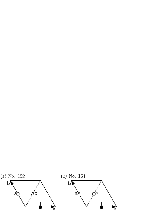
The -quartz (SiO2) and -berlinite (AlPO4) are known to have two crystal forms, the right-handed screw (space group No.152, ) and the left-handed screw (No.154, ). One is the mirror image of the other, thus the crystals are called to have different chirality. The two forms have been distinguished by using the optical activity since the discovery of Arago and Biot;Mas as linearly polarized light passes through the crystal, the direction of polarization rotates about the beam axis oppositely according to the chirality. Another method to distinguish chirality is the anomalous x-ray scattering by which atomic scattering amplitudes become complex numbers, Bijvoet et al. (1951); de Vries (1958) leading to the determination of atomic positions for systems with different chirality. Note that the conventional x-ray diffraction using Thomson scattering could not distinguish chirality.
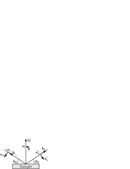
Recently, another method has been attempted to distinguish chirality: the resonant x-ray scattering (RXS) with circularly polarized beam. Tanaka et al. (2012a, 2011) The RXS process may be described at the Si K-edge in -quartz and at the Al K-edge in -berlinite as follows. The -core electron is prompted to unoccupied -symmetric states by absorbing photon [electric-dipole (E1) transition], and subsequently the excited electron is recombined to the core-hole by emitting photon (E1 transition). This will be called the E1-E1 process. Figure 1 shows the scattering geometry, where the sample is rotated by azimuthal angle around the scattering vector . It is known that the tensor character of the scattering matrix of RXS could give rise to the intensity on the spots forbidden in Thomson scattering.Templeton and Templeton (1982); Dmitrienko (1983); Dmitrienko et al. (2005) Measuring the spectra on the forbidden spots and , Tanaka et al.Tanaka et al. (2012a, 2011) have found characteristic patterns depending on chirality in the spectral intensity by means of switching polarizations from the right-handed one (RCP) to the left-handed one (LCP).
The purpose of this paper is to analyze such spectra from underlying electronic structures. We start by deriving the scattering matrix on the basis of symmetry requirement; the only assumption made is that the total resonant scattering matrix is the sum of the local scattering matrix Templeton and Templeton (1982); Dmitrienko (1983); Dmitrienko et al. (2005) on each Si or Al site. We introduce the local dipole-dipole correlation function instead of the local scattering matrix in this procedure, since the former quantity consisting of real numbers makes the expression transparent. We obtain a general formula of scattering matrix depending on polarization, chirality, and scattering vector. The scattering intensity contains the oscillation term as a function of azimuthal angle, which has a phase shift and the amplitude with chirality dependence different from previous ones. Lovesey et al. (2008); Tanaka et al. (2011, 2012b); Tanaka and Lovesey (2012)
The general expression of scattering matrix involves parameters undetermined by the symmetry argument alone. In this paper, we evaluate these parameters from underlying electronic structures by exploiting a simple bond-orbital model developed by Harrison.Har This model is known to work well on the ground-state properties in covalent-bonding systems; it considers the strong coupling between the sp3-hybrid on Si atoms and the sp1.24-hybrid on O atoms with four bonds per Si atom in -quartz. In -berlinite, Si atoms are replaced by Al and P atoms. In the ground state, the bonding states are occupied, while the anti-bonding states are unoccupied. In the intermediate state, one anti-bonding state is occupied at the core-hole site, on which the core-hole potential works. The parameters in the scattering matrix are evaluated by using the electronic structures thus determined. The spectral intensities are calculated depending on polarization, scattering vectors, and chirality as a function of azimuthal angle, reproducing the experimental curves particularly well for -berlinite. The present model calculation predicts the phase shift of oscillation to be for both -quartz and -berlinite. The experimental curves indicate the phase shift in -berlinite and its deviation from in -quartz. Tanaka et al. (2012a, 2011) Since both materials are expected to have similar electronic structures, such a difference is puzzling to us. The possible origin for the deviation will be discussed in the last section.
The present paper is organized as follows. In Sec. II, the crystal structures of -quartz and -berlinite are briefly described. In Sec. III, the scattering matrix is formulated from the symmetry requirement. In Sec. IV, the RXS intensity as a function of azimuthal angle is formulated for the incident x-ray beam specified by the Stokes parameters. In Sec. V, the bond-orbital model is introduced to evaluate the electronic structures as well as the RXS intensity. In Sec. VI, the calculated results are discussed in comparison with experiments. Section VII is devoted to the concluding remarks.
II Crystal structure
II.1 -quartz
The crystal structure of -quartz is hexagonal with three Si atoms per unit cell with Å, and Å. It has chirality described by two different space group (No.152), the right-handed screw, and (No.154), the left-handed screw. As shown in Fig. 2, Si atoms sit at the positions , , for No.152, while at the positions , , for No.154, where . One O atom sits between each nearest-neighboring Si-Si pair. Each Si atom is surrounded by a tetrahedron of O atoms. We introduce the Cartesian frame where and axes are parallel to the crystal and axes and the origin is set at the center of the Si atom labeled as 1 in Fig. 2. Then, the coordinates of O atoms of the tetrahedron are given by , , , in units of Å, where the upper and lower signs correspond to No.152 and No.154, respectively. Page and Donnay (1976) Note that there exists the symmetry of two-fold rotation around the -axis for both No.152 and No.154, and that the crystal of No.154 is the mirror image of No.152 with respect to the - plane. The settings correspond to the and settings for the crystals of No. 152 and No.154, respectively, in which the twofold axis develops charge at its positive end on crystal extension along the axis. Other tetrahedrons are given by rotating () and () around the axis with translating , along the axis for No.152 (No.154).
II.2 -berlinite
The crystal structure is close to the -quartz structure, where Si atoms are replaced by Al and P atoms alternatively along the -axis. Therefore, the unit cell is doubled along the -axis; there are three Al atoms and three P atoms per unit cell with Å, Å. More precisely, for No.152, Al atoms sit at , , , and P atoms at , , , with , while for No.154, Al atoms sit at , , , and P atoms at , , . In the Cartesian frame where the and axes are along the and axes, respectively, and its origin is the center of the Al site at , the coordinates of the O atoms of the tetrahedron are given by , , , in units of Å, where the upper (lower) sign corresponds to No.152 (No.154).Muraoka and Kihara (1997) Note that the tetrahedron surrounding Al for No.154 is similar to that for No.152 in -quartz. Other tetrahedrons surrounding Al are given by rotating (), () around the -axis with translating , along the -axis for No.152 (No.154), according to the screw symmetry.
III Scattering matrix
Let the incident and scattered photon polarizations be specified as and in Cartesian frame where the () and () axes are along the and axes. The scattering matrix at site , , may be expressed as
| (1) |
where the dipole operator is measured from the center of site . Ket represents the ground state with energy , and represents the intermediate state with energy (including the core-hole energy). The represents the life-time broadening width of the -core hole.
The total resonant scattering matrix could be well approximated by the sum of the local amplitudes at Si sites or at Al sites, since the state is localized at each Si site. The scattering geometry is shown in Fig. 1. For the incident and scattered wave vectors and , the total resonant scattering matrix may be expressed as
| (2) |
where runs over Si sites for Si -edge (quartz) and over Al sites for Al -edge (berlinite). The scattering vector is defined by .
To analyze the symmetry of the scattering matrix, it may be convenient to introduce the local dipole-dipole correlation function at the core-hole site , which is defined by
| (3) |
and the total dipole-dipole correlation function associated with , which is defined by
| (4) |
Using the latter quantity, we may express the total resonant scattering matrix as
| (5) |
Let the local dipole-dipole correlation function at site be with and signs corresponding to No.152 and No.154. It should take the following matrix form according to the local symmetry:
| (6) |
where , , , are real functions. The presence of the off-diagonal elements is due to the lack of the inversion symmetry around the Si atom in -quartz or the Al atom in -berlinite. The zero components are originated from the symmetry of the two-fold rotation around the -axis. The signs are originated from the mirror-image relation with respect to the - plane between No.152 and No.154, respectively.
Now we define the local correlation function rotated by around the -axis:
| (7) | |||||
| (8) |
where rotation matrix is defined by
| (9) |
For the crystal of No.152, the local dipole-dipole correlation function at and at are given by and , respectively. On the other hand, for the crystal of No.154, the local dipole-dipole correlation function at and at are given by and , respectively.
III.0.1
Summing up the local correlation function defined above with weight , we obtain the total dipole-dipole correlation functions for No.152 and No.154 as
| (13) | ||||
| (17) |
Note that there exist only two independent components and in the matrix. Hence, from Eq. (5), the total resonant scattering matrix is written as
| (18) |
with
| (19) | |||||
| (20) |
where the upper and lower signs correspond to No.152 and No.154, respectively. Note that and are complex numbers because of the presence of .
III.0.2
The total dipole-dipole correlation functions for No.152 and No.154 are given by
| (21) | |||||
| (22) |
Since , , , in and are real functions, we notice that the total resonant scattering amplitude is obtained from by replacing by . The result is
| (23) |
where the upper and lower signs correspond to No.152 and No.154, respectively.
III.0.3 and
Now that the phase factors are equivalent to , we immediately obtain the following relation:
| (24) | |||||
| (25) |
IV Polarization analysis with rotating crystal
Specifying the polarization vectors by () and () for incident (scattered) photon, we formally write the component of the total resonant scattering matrix as
| (26) | ||||
| (27) |
and so on. We will evaluate these values with rotating crystal in the scattering geometry described below.
IV.1 and
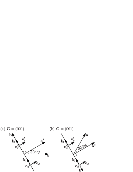
We rotate the crystal right-handedly around with azimuthal angle . Following the experimental setup by Tanaka et al., Tanaka et al. (2012a, b) we define the origin of such that the scattering plane contains the axis, that is, it is perpendicular to the reciprocal lattice vector conjugate to the translational vector along the axis, as shown in Fig. 3(a). Note that the rotation of the crystal indicates that the scattering plane is inversely rotated with respect to the crystal.
The polarization vectors, which are represented in the Cartesian frame with and axes along the crystal and axes, are given by
| (28) | |||||
| (29) | |||||
| (30) |
where , and is the Bragg angle of the scattering. Using Eq. (18), we obtain
| (31) | |||||
| (32) | |||||
| (33) | |||||
| (34) |
where the upper (lower) sign corresponds to the crystal of No.152 (No.154). We have abbreviated and by and , respectively. For , the corresponding components of scattering matrix are given by replacing by in Eqs. (31)-(34).
IV.1.1 Linear polarization
For the scattering channels with and , the scattering intensities are the same for both No.152 and No.154, and are constant as a function of azimuthal angle. On the other hand, for the scattering channels with and , the scattering intensities oscillate as a function of azimuthal angle.
For , the scattering intensities in the and channels are given by
| (35) | |||||
| (36) |
where the upper sign (lower) sign corresponds to the crystal of No.152 (No.154), and is replaced by . The phase could take any value in principle.
For , the corresponding intensities are given by Eqs. (35) and (36) with replacing by . Since , we could safely replace by . The constant term as well as the amplitudes of the oscillation are the same for both No.152 and No.154. Therefore, the knowledge of the phase shift of the oscillation is necessary in order to distinguish the chirality.
IV.1.2 Circular polarization of incident beam
We consider the case where the incident beam is circularly polarized. To include the partial polarization, we introduce the polarization density matrix,Lan which is represented on the bases and :
| (37) |
where , , are the Stokes parameters. All three parameters take values between and . In the unpolarized state, ; for a completely polarized photon, ; for the right(left)-handed circular polarization.
Without analyzing the polarization of scattered x-ray, the scattering intensity may be expressed in the following form:
| (38) | |||||
For , the coefficients are given by
| (39) | |||||
| (40) | |||||
| (41) | |||||
| (42) |
Thereby the scattering intensity with is expressed as
| (43) |
with
| (44) | |||||
| (45) |
IV.2 and
Following the experimental setup by Tanaka et al.,Tanaka et al. (2012a, 2011) we rotate the crystal by angle around the reciprocal lattice vector in order to use the reverse side of the crystal for the scattering, as shown in Fig. 3(b). The other scattering conditions are kept the same as those for and . Since the direction of is now opposite to , the right-handed rotation of crystal around the direction of means the left-handed rotation around the axis. The polarization vectors, which are represented in the Cartesian frame with the and axes along the crystal and axes, are given by
| (49) | |||||
| (50) | |||||
| (51) |
where . Thereby, from Eq. (23), we obtain
| (52) | |||||
| (53) | |||||
| (54) | |||||
| (55) |
These equations are nothing but Eqs. (31)-(34) with reversing signs in front of . For , are given by the same forms of Eqs. (52)-(55) with replacing by . With these expressions, the following results straightforwardly come out.
IV.2.1 Linear polarization
IV.2.2 Circular polarization
The , , and for are given by the same forms as Eqs. (39)-(42) with reversing the signs of the terms proportional to and . Thereby, the scattering intensity with is expressed as
| (57) |
with
| (58) | |||||
| (59) |
Equation (58) for is the same as Eq. (7) in Ref. [Tanaka et al., 2011] (see also the errata), if and are identified to be proportional to and . Equation (59) for is similar to Eq. (8) in Ref. [Tanaka et al., 2011] and to Eq. (11) in Refs. [Tanaka and Lovesey, 2012; com, a], but different from them concerning chirality dependence. In addition, the possible phase shift is absent in Eq. (6) in Ref. [Tanaka et al., 2011] and in Eq. (9) in Ref. [Tanaka and Lovesey, 2012].
Finally, , , and for are given by the same forms as those for with replacing by and with reversing the signs in the expression of for . Hence, the scattering intensity with is expressed as
| (60) |
with
| (61) | |||||
| (62) |
V Bond-orbital model analysis
We employ the bond-orbital model developed by HarrisonHar to describe the electronic structures of -quartz and -berlinite. We explain the model for -quartz by following Ref. [Har, ]. The extension of the model to -berlinite is straightforward by replacing one of the Si atoms by an Al atom and another one by a P atom in the Si-O-Si bond.
Consider the Si-O-Si bond shown in Fig. 4. There exist four such bonds for each Si atom. Let us introduce the Si sp3-orbitals, . For the O atom, we construct the oxygen hybrids to the left and right,
| (63) | |||||
| (64) |
where stands for the state, and , , stand for the states of O, respectively. Imposing the orthogonality condition , we have with being the bending angle of the bond. We may call the states by sp1.24-hybrid. We also construct the lone-pair orbital, which we write as
| (65) |
Imposing the orthogonality conditions to and , we have . This state as well as the oxygen orbital, , are assumed to have no coupling to other states. With the bases, , , , , the Hamiltonian matrix for each bond may be represented as
| (66) |
where is the energy of the sp3 state of Si. The , the hybrid energy of O, is given by , with and being the energies of and states of O. The covalent energy is given by
| (67) |
where , , and are the Slater-Koster parameters.Slater and Koster (1954) The represents the coupling between the two oxygen hybrids given by
| (68) |
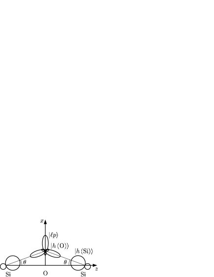
Table 1 shows the parameter values for -quartz and -berlinite. Most of them are taken from Table 12-1 in Ref. [Har, ]. The and are taken from Table 1-1 in Ref. [Har, ]. The covalent energy for Al-O and P-O are estimated from for Si-O by assuming the so-called dependence. The scattering intensities discussed later have been checked to be insensitive to the choice of parameter values.
| eV | eV | eV |
| eV | eV | eV |
| eV | eV | eV |
| deg | eV |
We diagonalize the Hamiltonian matrix to obtain the eigenvalues specified as , and the corresponding eigenstates denoted by (). In the ground state, four electrons are occupied on the lowest two levels, and , and furthermore four electrons are occupied on and .
The transition may be expressed as
| (69) |
where is the dipole operator on the Si site. with and being the radial wave function of and states. The is the annihilation operator of the 1s electron with spin , and is the creation operator of electron on orbital in the -th bond, where four bonds of Si-O-Si (or Al-O-P) are distinguished by . The denotes the directional cosine of the sp3 hybrid of the -th bond with respect to the axis, which is determined from the positions of oxygen atoms specified in Sec. II. The sum over should be restricted within the unoccupied states, i.e. . Coefficient is defined by , which is independent of .
In the intermediate state, an attractive potential from the -core hole is working, which is known to modify the absorption coefficient as a function of photon energy .Taillefumier et al. (2002) Assuming that the core-hole potential works within the Si or Al site, we change from to . We tentatively put eV. As shown below, the dependence on polarization, chirality, and scattering vector is unaltered by the presence of for fixed , although the spectral shape is modified as a function of . We diagonalize the Hamiltonian matrix to obtain the eigenvalues and the corresponding eigenstates (). The intermediate state is constructed by distributing five electrons on these energy levels in one of the four bonds (other three bonds are occupied four electrons).
The dominant contributions come from the intermediate states that four electrons occupy lowest two states and one electron occupies higher state. Thus, neglecting the so-called shake-up states in the intermediate state, we consider the overlap between the intermediate state and the ground state, and obtain the local dipole-dipole correlation function,
| (70) |
where
| (71) |
with
| (74) | |||||
| (78) | |||||
| (79) |
We notice from Eq. (70) that all the components , , , , are proportional to , and that their relative ratios are determined by the directions of Si-O or Al-O bonds. Hence we obtain and from Eqs. (19) and (20), which are proportional to
Accordingly is real for both -quartz and -berlinite, indicating that the phase shift is generally or , independent of . These simple result would be modified, if the coupling between bonds is taken into account.
VI Calculated results in comparison with experiments
VI.1 -quartz
Figure 5 shows the absorption coefficient calculated from Eq. (81), in comparison with the experiment.Tanaka et al. (2012a) The first and second peaks arise from the transition from the state to the unoccupied state , and to , respectively. The core-hole potential makes the first peak intensity increase. In actuality, there exist more -symmetric states forming band states, which make the intensities spread above the edge. The core-hole potential gives rise to the intensity transfer from the high energy region, resulting in sharpening the peak at the edge, as shown in Ref. [Taillefumier et al., 2002]. The states constituting the peak are close to the localized states constructed by the sp3-orbitals. Therefore the present model could describe rather well the states of the peak at the edge. Note that there exists a shoulder in the experimental curve of the absorption coefficient.Tanaka et al. (2012a) Such a peak is, however, not seen in the experimental and the theoretical curves in Ref. [Taillefumier et al., 2002]. The origin of this shoulder is not clear.
Note that the RXS intensity as a function of is proportional to
Although it is not shown here, this quantity has a large peak at giving the large peak in the absorption coefficient, in agreement with the experiment.Tanaka et al. (2012a)

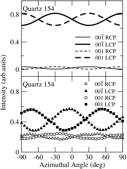
We concentrate our attention on the spectra at the giving the main absorption peak in the following. Figure 6 shows the RXS intensity as a function of azimuthal angle for . Although is defined by in the experiment, which is opposite to ours (see the errata in Ref. [Tanaka et al., 2012a]), we present ’s in our definition. The Stokes parameters are set to be , , in accordance with the experiment.Tanaka et al. (2012a) For , , . The calculated intensities are larger for RCP () than for LCP () in No.152, while the former is smaller than the latter in No.154, consistent with the experimental curves shown in panels (b) and (d).Tanaka et al. (2012a) The intensities for LCP in No.152 as well as for RCP in No.154 are, however, too small in comparison with the experiment. We hope that the absorption correction to the experimental data, if it were not made yet, as well as a careful subtraction of the background might improve the discrepancy. As regards the oscillation terms, we notice from the general expressions (Eqs. (57)-(59)) that they take the form of for RCP in No.152, and for LCP in No.154 with a positive number, and that they take the form of for LCP in No.152, and for RCP in No.154 with a positive number. The amplitude is much larger than the amplitude ; their ratio is given by , which is independent of the model. The experimental curves seem to belong to these forms with the phase shift . The present calculation within the bond-orbital model gives the phase shift .

Figure 7 shows the RXS intensities for both and in No. 154. According to the general expressions (Eqs. (43) and (57)), the oscillation terms are proportional to for both and , regardless of RCP or LCP, in No.154. This means that all curves have to be maximum or minimum at the same -values. This requirement seems not to be satisfied in the experimental curves, where the maximum and minimum positions are somewhat different, indicating that the phase does not seems to has a definite value.
VI.2 -berlinite
Figure 8 shows the absorption coefficient calculated from Eq. (81), in comparison with the experiment. Tanaka et al. (2011) Without taking account of the core-hole potential, we have the second-peak intensity larger than the first-peak one, which in fact is different from -quartz. The core-hole potential makes the first-peak intensity larger than the second one, in agreement with the experiment.Tanaka et al. (2011)

We concentrate our attention on the spectra at the giving the absorption peak. Figure 9 shows the RXS intensity for , where , . The Stokes parameters are set to be , , , in accordance with the experiment,Tanaka et al. (2011) where the value of here is opposite in sign to the case of -quartz.Tanaka et al. (2011) The average intensity for RCP is larger than for LCP in No.152, while the former is smaller than the latter in No.154, which dependence is the same as in -quartz. The oscillation terms take the same forms as for -quartz; the ratio of the amplitudes are given by . The present calculation gives the phase shift . The calculated curves are in good agreement with the experimental curves shown in panel (c).Tanaka et al. (2011) We would like to emphasize that there exist no adjustable parameter in the present calculation.

Figure 10 shows the RXS intensity for , where , . The Stokes parameters are the same as for . The intensity for LCP is larger than that for RCP in No.152, while the former is smaller than the latter in No.154. This dependence on polarization is opposite to that in . According to the general expressions (Eqs. (60) and (62)), the oscillation terms take the form of for RCP in No.152, and for LCP in No.154 with a positive number, while they take the form of for LCP in No.152, and for RCP in No.154 with a positive number. The ratio of the amplitude is given by , corresponding to the nearly flat curves for LCP in No.152 and for RCP in No.154. The calculated curves are in good agreement with the experimental curves shown in Panel (c).

VII Concluding Remarks
We have analyzed the RXS spectra at Si and Al K-edges on forbidden spots in chiral materials, -quartz and -berlinite. Summing up the local scattering matrices which satisfy the symmetry requirement, we have derived the general expression of scattering matrix on forbidden spots with E1-E1 process. We have obtained the oscillation term as a function of azimuthal angle, which has the phase shift and the amplitude with chirality dependence different from the previous studies. We have evaluated the parameters undetermined by the symmetry argument alone on the basis of the underlying electronic structures given by the bond-orbital model. With such evaluation, the scattering matrix is completely determined. We have calculated the spectra depending on polarization, chirality, and scattering vector in agreement with the experiments, although some discrepancies remain in the average intensities and the phase shift of oscillation in -quartz. The spectra for -berlinite have reproduced particularly well the experiment. It should be emphasized that this result is obtained without adjustable parameters.
We have obtained the phase shift of oscillation in both -quartz and -berlinite. For -berlinite, the phase shift is consistent with the experiment. Note that the same phase shift is also observed in the chiral metal Te.Tanaka et al. (2012b); com (b) On the other hand, the situation of -quartz is different, where the phase shift looks deviating from with depending on polarization and scattering vector (see the lower panel in Fig. 7). The present formula based on the symmetry requirement does not allow such dependence but allows dependence on photon energy. Since both materials belong to the same covalent-bonding with similar electronic structures, such difference in the spectra between -quartz and -berlinite is puzzling to us. To clarify the origin of the phase shift and to obtain better agreement with experiment, it may be necessary to take account of the coupling between the bond orbitals, or more precisely, the band effects. It might be necessary to consider the absorption correction to the experimental curves, if it were not made, for more quantitative comparison.
Finally we comment on the effect of the E1-E2 process. Since the space inversion symmetry is broken around Si sites in -quartz and around Al sites in -berlinite, the -symmetric states could mix with the -symmetric states, and therefore the second-order process using both the E1 transition and the electric-quadrupole (E2) transition could take place. This E1-E2 process is known to be important for x-ray absorption as well as RXS at the pre-K-edge in the transition-metal compounds such as -Fe2O3, Finkelstein et al. (1992) K2CrO4,Templeton and Templeton (1994) magnetite,Matsubara et al. (2005); Igarashi and Nagao (2008) and GaFeO3.Kubota et al. (2004); Arima et al. (2005); Matteo and Joly (2006); Igarashi and Nagao (2010) These spectra have been analyzed based on the symmetry or by taking account of the microscopic electronic structures.Matteo and Joly (2006); Igarashi and Nagao (2008) Now, for -quartz, it has been proposedTanaka et al. (2012a); Lovesey et al. (2008); Tanaka et al. (2011); Tanaka and Lovesey (2012) that the phase shift is brought about by adding the scattering amplitude coming from the E1-E2 process to that from the E1-E1 process. Since the former contribution is expected to be more than one order of magnitude smaller than the the latter, we think it unlikely to expect the substantial phase shift deviation from this mechanism.
Acknowledgements.
This work was partially supported by a Grant-in-Aid for Scientific Research from the Ministry of Education, Culture, Sports, Science and Technology of the Japanese Government.References
- (1) For a historical account, see for example, S. F. Mason, Molecular Optical Activity and the Chiral Discriminations (Cambridge University Press, 1982).
- Bijvoet et al. (1951) J. M. Bijvoet, A. F. Peerdeman, and J. A. van Bommel, Nature 168, 271 (1951).
- de Vries (1958) A. de Vries, Nature 181, 1193 (1958).
- Tanaka et al. (2012a) Y. Tanaka, T. Takeuchi, S. W. Lovesey, K. S. Knight, A. Chainani, Y. Tanaka, M. Oura, Y. Senba, H. Ohashi, and S. Shin, Phys. Rev. Lett. 100, 145502(2008); ibid. 108, 019901(E) (2012a).
- Tanaka et al. (2011) Y. Tanaka, T. Kojima, Y. Takata, A. Chainami, S. W. Lovesey, K. S. Knight, T. Takeuchi, M. Oura, Y. Senba, H. Ohashi, et al., Phys. Rev. B 81, 144104(2010); ibid. 84, 219905(E) (2011).
- Templeton and Templeton (1982) D. H. Templeton and L. K. Templeton, Acta Crystallogr. A 38, 62 (1982).
- Dmitrienko (1983) V. E. Dmitrienko, Acta Crystallogr. A 39, 29 (1983).
- Dmitrienko et al. (2005) V. E. Dmitrienko, K. Ishida, A. Kirfel, and E. N. Ovchinnikova, Acta Crystallogr. A 61, 481 (2005).
- Lovesey et al. (2008) S. W. Lovesey, E. Balcar, and Y. Tanaka, J. Phys.: Condens. Matter 20, 272201 (2008).
- Tanaka et al. (2012b) Y. Tanaka, S. P. Collins, S. W. Lovesey, M. Matsumami, M. Moriwaki, and S. Shin, J. Phys.: Condens. Matter 22, 1220(2010); ibid. 24, 159905(E) (2012b).
- Tanaka and Lovesey (2012) Y. Tanaka and S. W. Lovesey, Eur. Phys. J. Special Topics 208, 69 (2012).
- (12) W. A. Harison, Elementary Electronic Structure (Revised Edition) (World Scientific, 2004). References are therein.
- Page and Donnay (1976) Y. L. Page and G. Donnay, Acta. Cryst. B 32, 2456 (1976).
- Muraoka and Kihara (1997) Y. Muraoka and K. Kihara, Phys. Chem. Materials 24, 243 (1997).
- (15) V. B berestetskii, E. M. Lifshitz, and L. P. Pitaevskii, Quantum Electrodynamics (Butterworth-Heinemann, 1982), Sec. 8.
- com (a) and in Ref. [Tanaka and Lovesey, 2012] are and in Ref. [Tanaka et al., 2011], respectively.
- Slater and Koster (1954) J. C. Slater and G. F. Koster, Phys. Rev. 94, 1498 (1954).
- Taillefumier et al. (2002) M. Taillefumier, D. Cabareti, M. Flank, and F. Mauri, Phys. Rev. B 66, 195107 (2002).
- com (b) In Ref. [Tanaka et al., 2012b], the origin of is defined such that the scattering plane includes , which is different from the definition in the experiments of -quartz and -berlinite.
- Finkelstein et al. (1992) K. D. Finkelstein, S. O, and S. Shastri, Phys. Rev. Lett. 69, 1612 (1992).
- Templeton and Templeton (1994) D. H. Templeton and L. K. Templeton, Phys. Rev. B 49, 14850 (1994).
- Matsubara et al. (2005) M. Matsubara, Y. Shimada, T. Arima, Y. Taguchi, and Y. Tokura, Phys. Rev. B 72, 220404 (2005).
- Igarashi and Nagao (2008) J. Igarashi and T. Nagao, J. Phys. Soc. Jpn. 77, 084706 (2008).
- Kubota et al. (2004) M. Kubota, T. Arima, Y. Kaneko, J. P. He, X. Z. Yu, and Y. Tokura, Phys. Rev. Lett. 92, 137401 (2004).
- Arima et al. (2005) T. Arima, J. H. Jung, M. Matsubara, M. Kuboki, J. P. He, Y. Kaneko, and Y. Tokura, J. Phys. Soc. Jpn. 74, 1419 (2005).
- Matteo and Joly (2006) S. D. Matteo and Y. Joly, Phys. Rev. B 74, 014403 (2006).
- Igarashi and Nagao (2010) J. Igarashi and T. Nagao, J. Phys. Soc. Jpn. 79, 014705 (2010).