Acrylic purification and coatings
Abstract
Radon (Rn) and its decay daughters are a well-known source of background in direct WIMP detection experiments, as either a Rn decay daughter or an alpha particle emitted from a thin inner surface layer of a detector could produce a WIMP-like signal. Different surface treatment and cleaning techniques have been employed in the past to remove this type of contamination. A new method of dealing with the problem has been proposed and used for a prototype acrylic DEAP-1 detector. Inner surfaces of the detector were coated with a layer of ultra pure acrylic, meant to shield the active volume from alphas and recoiling nuclei. An acrylic purification technique and two coating techniques are described: a solvent-borne (tested on DEAP-1) and solvent-less (being developed for the full scale DEAP-3600 detector).
Keywords:
Dark matter, WIMPs, low radioactivity techniques, purification, polymers:
95.35.+d, 81.20.Ym, 81.15.Rs, 81.15.Gh1 Introduction
DEAP-3600 is a dark matter detector, currently under construction at SNOLAB, designed for a three year background-free run with a 1000 kg sensitive liquid argon target (single phase), with sensitivity to spin-independent WIMP-nucleon scattering with cross-sections as low as 10-46 cm2 per nucleon. DEAP-1, a 7 kg liquid argon prototype detector, has been operated underground for background studies since 2008. Backgrounds coming from natural sources of radiation (neutrons, and -particles) are the largest challenge of the project and are more generally discussed elsewhere Bei . Both DEAP detectors essentially consist of an acrylic vessel (AV), coated from inside with a wavelength shifting film (tetraphenyl butadiene, TPB) and filled with LAr. The scintillation light from LAr, shifted into the visible range is detected in external photomultiplier tubes.
One particular source of backgrounds is caused by alpha decays of radon decay daughters in a thin surface layer of the acrylic vessel (see Bei ). As Rn diffusion length in acrylic is 0.11 mm Wojcik , it is planned to use a resurfacing robot to remove up to 1 mm of material from the inside of the AV. However, the material may become saturated with Rn even before the acrylic is cast: either during storage (as acrylic beads of small diameter) or as liquid monomer, before the actual polymerization. In that case, the background from residual bulk contamination would still be visible. Detailed knowledge of the history of particular stock and details of the industrial polymerization process are necessary to exclude the possibility of the bulk contamination.
A stringent requirement on the 210Pb content ( g/g) in acrylic motivated us to: 1) put in place a quality assurance program with the acrylic supplier, 2) work on a sufficiently sensitive direct assay technique for 210Pb and 3) find a way to coat inner acrylic surfaces with a layer of ultra pure material, sufficiently thick to stop alpha particles coming from the decays in the bulk, which is described in detail in this document.
The ultra pure coating will be needed for DEAP-3600, if the acrylic purity or assay sensitivity prove insufficient to meet the requirements. A successful method has been found and tested with DEAP-1, work is ongoing to scale it up for DEAP-3600.
2 Requirements for the coating
In order to find an optimal candidate for the coating material, the following list of requirements was taken into account:
- Impenetrable for
-
The most likely background event source would be the 5.3 MeV alpha from 210Po decay, which has a typical range of several tens of microns, depending on material density and composition, e.g. 34 microns in acrylic SRIM . To set the scale, the highest alpha energy available from U/Th decay chains 8.78 MeV alpha from 212Po decay (extremely unlikely to be present in the bulk), in acrylic has a range of 75 microns. Thus depending on the coating material, a thickness ranging from 50 to 100 microns is necessary.
- Transparency
-
High attenuation length for wavelength from the TPB emission spectrum (380–500 nm), refractive index closely matched to acrylic, i.e. around 1.5.
- Stability
-
The coating has to survive the cool-down to liquid argon temperature without delamination or any other damage, which translates to: coefficient of thermal expansion (CTE) closely matched to acrylic, also good adhesion to acrylic.
- Possible to purify
-
As distillation is the most effective purification technique, it is preferable to start the process with liquid compounds.
- Compatibility
-
Coating process and chemicals used should be sufficiently compatible with acrylic and should not excessively dissolve or induce crazing in the substrate. Stressed PMMA is particularly sensitive to chemical attack and crazes when in contact with most common organic solvents.
- Non-scintillating
-
Not to introduce a new source of backgrounds.
The coating has to be applied between the TPB and the acrylic substrate. Overcoating the TPB is not feasible as the only group of materials capable of transmitting VUV light (LAr scintillation peak is around 128 nm) are fluorides, such as MgF2. The thickest stable coatings of that type are 1 micron thick MgF2 , which is insufficient to shield alphas.
Requirement of mechanical stability and CTE matched to acrylic removes pretty much all other inorganic compounds, limiting the choice to other plastics/polymers only. A conclusion was reached that the best coating material would be either PMMA itself or some other polymer from the same family as PMMA, i.e. some other poly methacrylate or poly acrylate. Most of these compounds closely match the acrylic index of refraction and have very similar CTE. The polymerization process is relatively simple: based on free radical polymerization of a liquid monomer, which can be either thermally or UV induced. Simple (meth-)acrylates do not contain aromatic rings and thus do not scintillate. Finally, the solubility of different polymers from the family in common solvents and also their blend miscibility with PMMA varies significantlyHarton05 . It should be possible to find a combination of monomers (and possibly solvents) sufficiently gentle for an acrylic substrate, yet capable of depositing a stable layer of clean material.
3 Coating Methods
For polymethacrylate coatings several production methods are possible:
-
1.
Solvent-borne. A solution of a polymer in an organic solvent is directly applied to the surface and left for drying. Application methods include: casting, brush painting, spraying, dipping and spin coating.
-
2.
Chemical vapor deposition. Developed fairly recently ChanPhD ; Chan05 ; Anthamatten08 . Monomer and initiator vapors are introduced to an oxygen-free reaction chamber with the substrate. The initiator is activated either thermally or optically and turns into free radicals, which sustain growth of a polymeric coating on the substrate surface.
-
3.
Hybrid approach (in-situ polymerization). The monomer with small admixture of a photoinitiator directly applied to the surface (as in the first method), polymerization is then induced thermally or optically.
For the DEAP-1 chamber, the solvent-borne option was chosen as technically the simplest one. Because of the cylindrical geometry, limited amount of material and required uniformity of the layer, spin coating was selected as the application method. An important factor was also the existing experience in production of 3 micron PS coatings with that technique (Kuzniak08, , Sec. 5.4.2) and reported successful production of much thicker 100 micron PMMA coatings with rotation speed increased to 1000 RPM Gao06 . For the windows, which are flat acrylic discs, casting was selected as the easiest and potentially cleanest of all possibilities.
In case of DEAP-3600, solvent-borne methods are not recommended, as introducing large amount of solvent into the AV would increase the risk of crazing (achievable PMMA concentrations are around 5–10% only). This is not an issue for DEAP-1, where acrylic is essentially stress free. Ongoing R&D on scaling-up one of two remaining solvent-less methods is described later in the paper.
4 Purification scheme
Water extraction, filtering, adsorption, distillation are well known ways to purify liquids. Generally, distillation can be considered the most effective one, which is a conclusion reached by many other low background experiments, including Borexino, KamLAND and SNO+. Also, for even better purity, distillation can be done multiple times or combined with adsorption on a porous material. Water extraction would not be feasible, as both most acrylic monomers and relevant solvents mix very well with water.
Relevant contaminants in our case are 210Po and 210Pb, as we already know that U/Th content near our target specification should be feasible even with commercial acrylic.
In terms of achievable purification factors, there is a reported factor of 104 reduction for 212Pb in linear alkyl benzene (LAB, TB=282–302 °C), achieved by vacuum distillation combined with adsorption on Al2O3 (alumina) powder (Quirk08, ; Lan07, , Sec. 4.5) and the reported reduction with the distillation alone is about 4 times lower. Also, three different adsorbants are compared (alumina, silica gel and HZrO loaded silica gel), with alumina being the best one (Quirk08, , Sec. 4.4). The purification factor due to adsorption on alumina only was around 2000.
More detailed studies on pseudocumene (PC, TB=170 °C) purification through adsorption on silica gel performed for Borexino and KamLAND indicate reduction for 210Pb and for 210Po in a small scale setup (Niedermeier05, , Tab. 4.26). Reduction factors from the range of 10–100 either on silica gel or alumina were reported for 212Pb (Keefer09, , Tab. 6.5). Distillation yielded reduction factors up to 3 for 212Pb (Keefer09, , Sec. 6.3), with the final content of around g/g.
Data on Po removal through distillation is sparse and probably the best clue available is a purification factor of “greater than 50090 for 210Po removal”, reported in Ref. (Leung06, , Sec. 4.11). Polonium is known to be more difficult to remove than Pb because of its non-trivial volatility Mabuchi58 ; Mabuchi63 ; Martin69 ; Hussain95 ; MurrayMatthews07 ; Momoshima01 . Some results indicate than adsorption cannot be considered the primary purification technique, because it is not effective against organometallic Pb and Po compounds (Keefer09, , Sec. 6.3.7). Still, the general consensus in the field is that the distillation is the most efficient method, and there are some indications that adsorption could additionally improve the purity. Moreover, because of the fact that boiling points of ACN (82 °C) and MMA (101 °C) are significantly lower than for LAB or PC, even greater purification factor should be achievable for DEAP.
Purification of solids via distillation is a little more problematic as it requires both highly reduced pressure and high temperature. No published data on purification efficiency of the wavelength shifter was found up to date. However, the vacuum evaporation process used to deposit TPB coatings in DEAP is effectively equivalent to distillation, so should result in a substantial purification of the wavelength shifter. Therefore no dedicated distillation setup was planned, although certain improvements described later were added to the evaporation procedure. A dedicated TPB distillation setup is certainly planned for the future application in DEAP-3600.
5 PMMA coating for DEAP-1
Initial tests
Achievable concentrations, drying time and cast coating quality and uniformity were investigated for several common solvents: acetone, acetylonitrile (ACN), tetrahydrofuran (THF), toluene and, finally, the methyl methacrylate monomer (MMA). ACN and THF turned out to be the best, allowing to use concentrations close to 10%. Eventually ACN was chosen, as THF might introduce some additional safety hazards during distillation (due to its tendency to form explosive peroxides). It was also observed that solubility strongly depends on details of polymerization process (high level of cross-linking reduces the solubility).
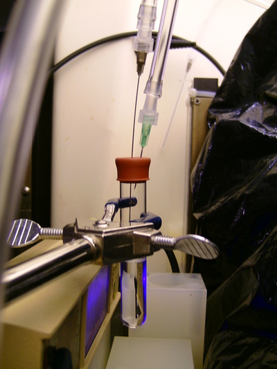
Commercially available MMA contains small amount of inhibitor (typically hydroquinone), which reduces the risk of spontaneous, egzothermic polymerization of large quantities of MMA. The inhibitor is removed via dripping the monomer through a filtration column filled with alumina powder (Al2O3). Also oxygen is a very potent polymerization inhibitor, thus the polymerization process has to be performed in an inert N2 atmosphere. Figure 1 shows a typical polymerization test setup.
Polymerization has to be started with free radicals, typically produced by break-up of initiator molecules. Although MMA and some other methacrylates can self-polymerize when illuminated with short wave UV radiation (around 254 nm), i.e. act as their own initiators, the resulting polymer is highly cross-linked and, in consequence, insoluble. Initiators are usually very reactive, sometimes unstable and tend to decompose at elevated temperatures, thus are not suitable for distillation. Majority of common initiators are solids at room temperature, with a notable exception of azoinitiators, such as easily available 2,2’-azobis(2-methylpropane), ABMP (also called azo-tert-butane), our final choice. Required initiator concentration is usually of the order of 0.1%, therefore its purification via adsorption would overall provide a sufficient purification factor (see Sec. 4). Another advantage of azoinitiators is that their decomposition into free radicals is induced with long-wave UV light (366 nm), which is not damaging to the base acrylic Chan05 .
The spin coater was designed to operate at 500 RPM rotational speed with the DEAP-1 acrylic insert for several hours. Thin teflon foil rings were used as a soft seal between Delrin endcaps (attached to a rotating rod) and the insert.
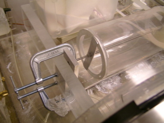
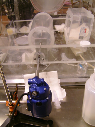
The spin coater was installed in a glovebox, held rigidly by two acrylic bars. The motor was attached to the table outside of the glovebox, with a feedthrough for the rotating rod installed in the wall of the glovebox. An external motor had to be used, in order to minimize Rn emanation inside the glovebox. All parts of the spin coater were ultrasonically washed before installation in the glovebox. The complete assembly is shown in Fig. 2.
Final production
In order to obtain 100 µ m thick coating for inner DEAP-1 surfaces, including some reasonable safety margin about 23 g of purified acrylic were necessary. In order to have some extra material for witness samples, it was planned to distill about 30 ml MMA and 450 ml of ACN.
-
1.
Solvent distillation. 2/3 of the large distillation flask (1 l capacity) of HPLC grade ACN was used for the distillation with addition of Al2O3. The distillation was performed at 280 Torr pressure and around 50 °C temperature (with constant N2 purge, see Fig. 3).
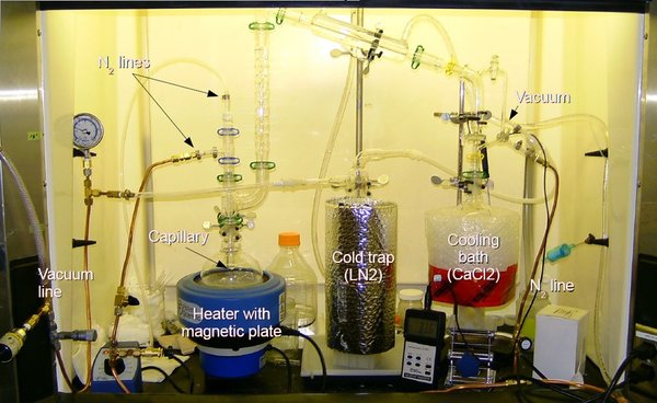
Figure 3: The distillation apparatus at Queen’s. -
2.
Monomer distillation. MMA taken for the distillation had already been dripped through a filtration column with alumina, in order to remove the inhibitor. During the distillation, as an additional precaution to minimize risk of spontaneous polymerization inside the apparatus, its ’hot’ parts and the condenser were covered with black plastic foil and the fume hood lamp was not used. The distillation was performed at 160 Torr pressure and around 50 °C.
-
3.
Polymerization. Small amount of alumina and a small magnetic stirrer was added to a vial containing ABMP, and the mixture was stirred for several hours inside the glove box. Then it was opened, sucked into a clean syringe and pushed through 0.2 µ m PTFE filter into the flask with distilled monomer. After re-sealing (with a tap), the flask was taken out of the glove box, attached to a N2 purge line and illuminated with an UV lamp (PASCO OS-9286A). Gas purge was used during the polymerization. After only 30 minutes, the material was already fully polymerized. The flask was resealed and taken back to the glove box. Chunk of PMMA was then fragmented into smaller pieces with a pair of clean stainless steel nippers, put in a 500 ml cleaned and etched Erlenmeyer flask with distilled ACN and a teflon magnetic stirrer. The mixing was speeded up with a NiCr heater.
-
4.
Applying. Acrylic windows were levelled and fixed inside large diameter band clamps sealed with PTFE tape before introducing them to the glove box. Dissolved acrylic was poured on their surfaces from a graduated cylinder, distributed uniformly and left for drying. For spin-coating about a half of acrylic paint was poured into the acrylic insert, which was then slowly rotated several times in order to wet the entire inner surface, then the rotation speed was slowly ramped up above 500 RPM. After a total time of 5h30m the coating was transparent, uniform and dry (see Fig. 4). Based on the amount of paint used, the approximate estimate of the coating thickness is 80 µ m .

Figure 4: DEAP-1 acrylic insert with a solidified coating, after disassembling the spin coater. Windows and the insert were then outgassed in vacuum for several days.
6 Scale-up for DEAP-3600
The inner surface area of DEAP-3600 is approximately 9 m ^ 2 . A 100 µ m thick acrylic coating on that surface translates into about 1 kg total mass of the extra layer. Regardless of technical details of the application, the main difficulty with solvent-borne methods is the necessity to evaporate 10 liters of solvent from the acrylic vessel (AV), which is a very confined volume. In consequence, the acrylic vessel would have to be exposed to aggressive solvents for an extended period of time, which could increase the risk of crazing. This motivated us to search for an alternative method and test it in a simplified geometry. In both cases described below, the plan is to eventually integrate coating applicators as with the resurfacer robot, planned for DEAP-3600.
Chemical Vapor Deposition
Chemical vapor deposition (CVD) occurs when a coating is produced as an effect of reactions occuring in gas phase (in a controlled mixture of a precursor gas and an initiator). The method has been known for a long time and typically used to deposit inorganic layers of silicon, oxides, nitrides or different types of carbon structures, including diamond. Usually the process requires very high temperatures (well beyond 500 °C).
At the beginning of the decade, which is fairly recently, a group from MIT has tuned and optimized the hot filament CVD (HFCVD) method for production of thick PTFE and other polymeric coatings Lau03 ; PryceLewis09 . Deposition rates of 1 µ m /min have been reported and the method had a good potential for scalability.
A detailed experimental and theoretical study was later done on HFCVD of poly methacrylate polymers ChanPhD , including PMMA. Also, instead of hot filaments, a combination of UV light and UV sensitive initiator (ABMP) was also successfully tested Chan05 . For poly methacrylates, generally, deposition rates up to 100 nm/min were reported in those pioneer experiments, proportional to the UV light intensity. Since the deposition rates were anti-correlated with the monomer saturated vapor pressure, heavier monomers, such as e.g. cyclohexyl methacrylate (CHMA) would result in significantly higher deposition rates than methyl methacrylate (MMA).
Further study was performed in a modified geometry Anthamatten08 , with a cylindrical deposition head instead of a matrix of hot filaments.
Given all that information, it seems feasible to develop a system capable of overcoating the AV on the time scale of up to several weeks. In terms of the deposition rate, CHMA was chosen as the most promising monomer, also the UV induced CVD (because of the potential of increasing the rate with higher light intensity). Operating at the atmospheric pressure is desirable for the resurfacer vacuum compatibility reasons.
CVD tests at Queen’s
A small test CVD chamber was constructed at Queen’s at the end of 2009 in order to achieve the deposition rate of at least 1 µ m / min 111A requirement based on two 100 c m ^ 2 coating heads operating inside AV for several weeks. It consists of a couple of CF tees, with a viewport (glass window or UV transparent FEP foil) and a water cooled deposition monitor located 2 inches below (see Fig. 5).
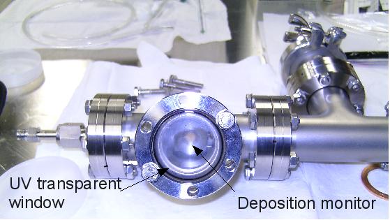
Two N2-purged bubblers, one with the monomer and the other with the initiator, are connected to the chamber and there is also a water filled outlet bubbler to prevent ambient air (especially oxygen) from entering the volume.
After the initial purge, the monomer bubbler temperature would be ramped up to 80 °C and the light source would be turned on. Effect of different flow rates through both bubblers on the deposition rates could be observed thanks to the deposition monitors. In some cases a couple of additional glass slides were introduced to the chamber around the deposition monitor in order to measure the coating thickness directly with a profiler. Figure 6 shows a typical scan and a microscope picture of one of the first coatings deposited.

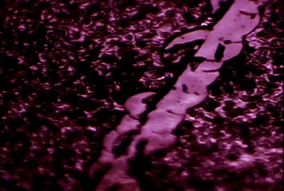
A maximum deposition rate of about 100 nm/min was achieved at that time, with a PASCO OS-9286A light source.
Since that time several changes were introduced to the setup. Most importantly, the mercury UV light source was changed to an UV LED head222OmniCure LX400 spot curing system from EXFO., capable of delivering 1 W/ c m ^ 2 at the substrate surface. The new source not only provides much more intensity, its bandwidth (36520 nm) is better tuned with the characteristics of ABMP (the UV initiator). Additionally, to maximize the intensity even further, the glass window in the viewport was replaced with a UV transparent FEP foil. Varying the temperature of the bubbler with the initiator was also tested (between -20 °C and the room temperature). It was also tried to deliver the initiator vapor very close to the surface, to prevent earlier mixing with the monomer vapor (a thin teflon tube inside the chamber was added).
Tests are still ongoing, but some preliminary conclusions can be already made. Deposition rates slightly above 1 µ m / min were achieved, however, a larger increase was expected, assuming that the UV intensity was the only scaling factor. At that rate other limiting factors may come into play, such as the rate at which the monomer vapor is delivered to the chamber and is then adsorbed on the substrate surface. If further tests confirm this, the conclusion can be made that the CVD method would work for DEAP-3600, although at the limit of its feasibility. It also means that another, possibly even easier approach could be more effective (see below).
Outlook
Since the material transport rate might be the bottle neck of the process, it was recently proposed to test a hybrid method: spray the monomer/initiator mixture on the inner AV surface and then UV polymerize it. Tests performed on highly stressed acrylic dogbones indicate that crazing in contact with CHMA starts after several hours, to be compared with seconds in case of MMA. Therefore spraying a thin layer of liquid on the AV surface and curing it within 30–60 minutes should be sufficiently safe. With no solvent used in the process, the total amount of liquid to deal with is on the order of one liter for the entire AV.
An appropriate supplier and a spraying system capable of depositing very thin and uniform layers have been identified, it is an airless automated industrial gun, with both the monomer and compressed gas (for valve control) delivered at 30 psi pressure. Its specification make it easy for incorporation in the resurfacer.
7 Summary
The risk of an additional source of background caused by bulk contamination of acrylic with radon daughters and resulting alphas has been identified. The ultra pure coating may be necessary for the experiment if the acrylic assay results are not satisfactory.
The proposed purification method is based on distillation and adsorption and has been widely used in low background physics experiments for other chemicals. A purification setup has been constructed at Queen’s, successfully used and is available for the future (it would be sufficient for the full scale purification).
A solvent-based spin coating method has been developed and used to produce a new DEAP-1 chamber. Technically, the method worked very well, although no significant improvement was reached in DEAP-1 background rate. Evidence was found that currently a dominant fraction of the rate is still induced by radon and thoron emanation in the process systems. Other methods are being developed to remove these sources and the level of the bulk contamination in acrylic remains an open question.
Chemical vapor deposition has been considered an interesting option for DEAP-3600. It was managed to produce multi-micron thick coatings using a small CVD chamber and achieve a high deposition rate. Tests are still ongoing. There is also a new, possibly more robust technique, which we are starting to work with. It is based on spraying the liquid monomer on the surface and then UV curing it. Last series of optimization steps will be possible with a new test setup available shortly. The final design of the applicator, based on test results, is expected in the first half of 2011.
References
- (1) B. Cai et al. (DEAP), “Surface backgrounds in the DEAP-3600 dark matter experiment”, Low Radioactivity Techniques (LRT2010) Workshop Proceedings, 2010.
- (2) M. Wojcik, Nucl. Instr. and Meth. B61, 8 (1991).
- (3) J. Ziegler, http://www.srim.org.
- (4) “Properties of MgF2 Films”, http://www.cerac.com/pubs/proddata/mgf2.htm.
- (5) S.E. Harton et al., Macromolecules 38, 10511–10515 (2005).
- (6) K. Chan, “Initiated Chemical Vapor Deposition of Polymeric Thin Films: Mechanisms and Applications”, Ph.D. Thesis, MIT, Boston, 2005.
- (7) K. Chan and K. Gleason, Langmuir 21, 11773–11779 (2005).
- (8) X. Chen and M. Anthamatten, Polymer 49, 1823–1830 (2008).
- (9) M. Kuźniak, “The Neutron Electric Dipole Moment Experiment: Research and Development for the New Spectrometer”, Ph.D. Thesis, Jagiellonian University, Kraków, 2008.
- (10) Y. Gao et al., J. Mater. Res. 21, 2246–2254 (2006).
- (11) S.E. Quirk, “Purification of Liquid Scintillator and Monte Carlo Simulations of Relevant Internal Backgrounds in SNO+”, M.Sc. Thesis, Queen’s University, Kingston, 2008.
- (12) C. Lan, “SNO+ and Geoneutrino Physics”, M.Sc. Thesis, Queen’s University, Kingston, 2007.
- (13) L. Niedermeier, “High Efficiency Purification of Liquid Scintillators for the Solar Neutrino Experiment Borexino”, Ph.D. Thesis, Technische Universität München, München, 2005.
- (14) G.J. Keefer, “First Observation of 7Be Solar Neutrinos with KamLAND”, Ph.D. Thesis, The University of Alabama, Tuscaloosa, 2009.
- (15) M. Leung, “The Borexino Solar Neutrino Experiment: Scintillator Purification and Surface Contamination”, Ph.D. Thesis, Princeton University, Princeton, 2006.
- (16) H. Mabuchi, Bull. Chem. Soc. Japan 31, 245–246 (1958).
- (17) H. Mabuchi, J. Inor. Nucl. Chem. 25, 657–660 (1963).
- (18) A. Martin and R.L. Blanchard, Analyst 94, 442–446 (1969).
- (19) N. Hussain et al., Aquatic Geochemistry 1, 175–188 (1995).
- (20) K. Murray Matthews et al., Applied Radiation and Isotopes 65, 267–279 (2007).
- (21) N. Momoshima et al., Environ. Sci. Technol. 35, 2956–2960 (2007).
- (22) K.K.S. Lau et al., J. Fluorine Chem. 122, 93–96 (2003).
- (23) H.G. Pryce Lewis et al., Thin Solid Films 517, 3551–3554 (2009).