Spontaneous Capillarity-Driven Droplet Ejection
Abstract
The first large length-scale capillary rise experiments were conducted by R. Siegel using a drop tower at NASA LeRC shortly after the 1957 launch of Sputnik I. Siegel was curious if the wetting fluid would expel from the end of short capillary tubes in a low-gravity environment. He observed that although the fluid partially left the tubes, it was always pulled back by surface tension, which caused the fluid to remain pinned to the tubes’ end. By exploiting tube geometry and fluid properties, we demonstrate that such capillary flows can in fact eject a variety of jets and drops. This fluid dynamics video provides a historical overview of such spontaneous capillarity-driven droplet ejection. Footage of terrestrial and low earth orbit experiments are also shown. Droplets generated in a microgravity environment are times larger than those ejected in a terrestrial environment. The accompanying article provides a summary of the critical parameters and experimental procedures. Scaling the governing equations reveals the dimensionless groups that identify topological regimes of droplet behavior which provides a novel perspective from which to further investigate jets, droplets, and other capillary phenomena over large length scales.
1 Introduction
“Spontaneous Capillarity-Driven Droplet Ejection” is a short video that provides a demonstration of the auto-ejection of a liquid from a tube under the influence of capillary forces alone. Attention is given to the historical significance and potential research applications of auto-ejection in terrestrial and low-g environments.
NASA scientist R. Siegel was the first to ponder auto-ejection from cylindrical tubes [1]. We repeat Siegel’s experiments. Footage of the experiment shows the liquid meniscus rise up the partially submerged tube, pin at the lip of the tube, invert, retract, and remain pinned at the tube’s end. Siegel concluded that auto-ejection was not possible. De Gennes et al. [2] use a pressure argument to confirm Siegel’s results. However by exploiting tube geometry we demonstrate liquids can in fact auto-eject from a tube’s end provided sufficient inertia is generated to overpower surface tension forces.
2 Analysis
Figure 1 introduces the nomenclature of the problem. The fluid wets the interior walls of the partially submerged tube creating a pressure drop. In the absence of gravity the fluid is ‘pumped’ along the tube, accelerates in the nozzle and if sufficient velocity is achieved, can eject from the tube end.
When , where is the residence time of liquid in the nozzle, is the viscous diffusion time of the flow, is the volume of the nozzle, is the flow rate entering the nozzle, is the average nozzle radius, and is the dynamic viscosity, all complexities of the flow in the nozzle due to developing boundary layers, significant viscous normal stresses leading to large dynamic contact angles, and capillary wave dynamics can be ignored and the constricting flow through the nozzle can be assumed to be laminar and inviscid.
Figure 2 depicts events of ejection we consider for analysis.
Since the velocity of the meniscus in Figure 2a at position 1 is relatively simple to measure and model [5], the critical condition for ejection is written in terms of said velocity. As the flow accelerates through the nozzle the pressure decreases (See Figure 2a-b). Applying continuity, the flow rate at each end of the nozzle must balance such that
| (1) |
where is the model loss coefficient ascribed to the nozzle and . The meniscus must invert as depicted in Figure 2c. The accompanying increase in pressure results in a reduction in velocity from position 3 to 4 given by
| (2) |
where amd are the fluid density and surface tension, respectively. Substituting 1 into 2 yields
| (3) |
Velocities below this level ‘cannot’ invert in the nozzle. After the inversion the flow must still have sufficient inertia to overpower the surface tension force that resists the continued flow required to extend past the Rayleigh breakup length . Balancing inertial and surface tension forces at the end of the nozzle yields the condition above which ejection is expected:
| (4) |
Substitution of 3 into 4 yields
| (5) |
Introducing modified Weber number , Eq. 5 reduces to
| (6) |
revealing a condition necessary for auto-ejection to occur. Similar scaling of equation 3 reveals that the condition is not likely to eject.
3 Experiments
The video footage shows a selection of the 200 experiments we conducted using Portland State University’s 2.1s Dryden Drop Tower. Additional footage of experiments in a terrestrial lab and aboard the International Space Station(ISS) are also shown. We provide brief descriptions of the experiments’ setup and procedures below.
3.1 Drop tower experiments
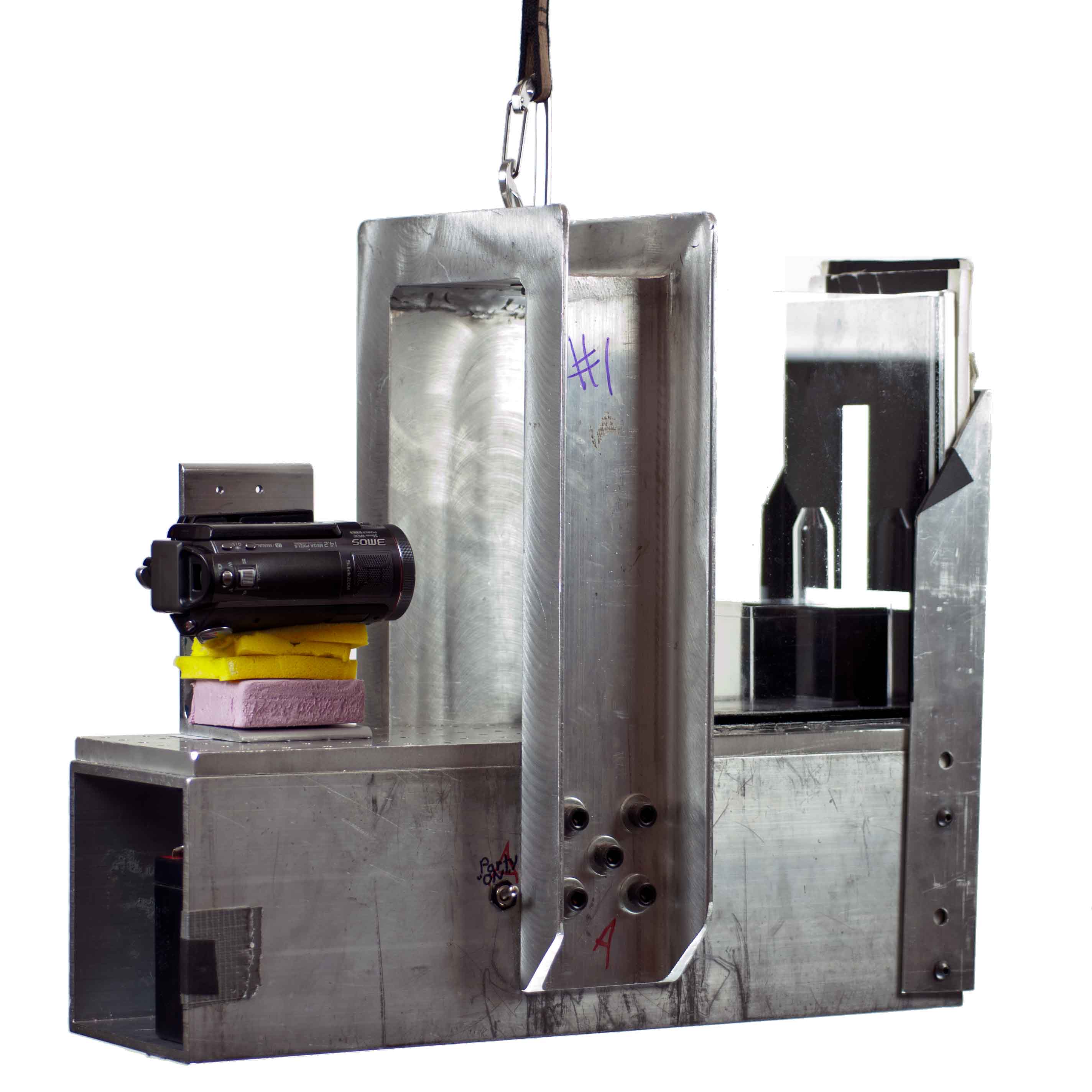
Figure 3 shows an annotated schematic and photograph of the drop tower experiment rig. Simax Glass tubes are employed with nozzles formed by heating, pulling, and grinding. The tubes are partially submerged in a liquid reservoir which is mounted to the experiment rig. The experiment rig is released for 2.1s of freefall inside a drag shield within the drop tower. Cameras image the ensuing capillary rise at 60fps or 400fps. Sample footage is provided in the video.
3.2 Experiments
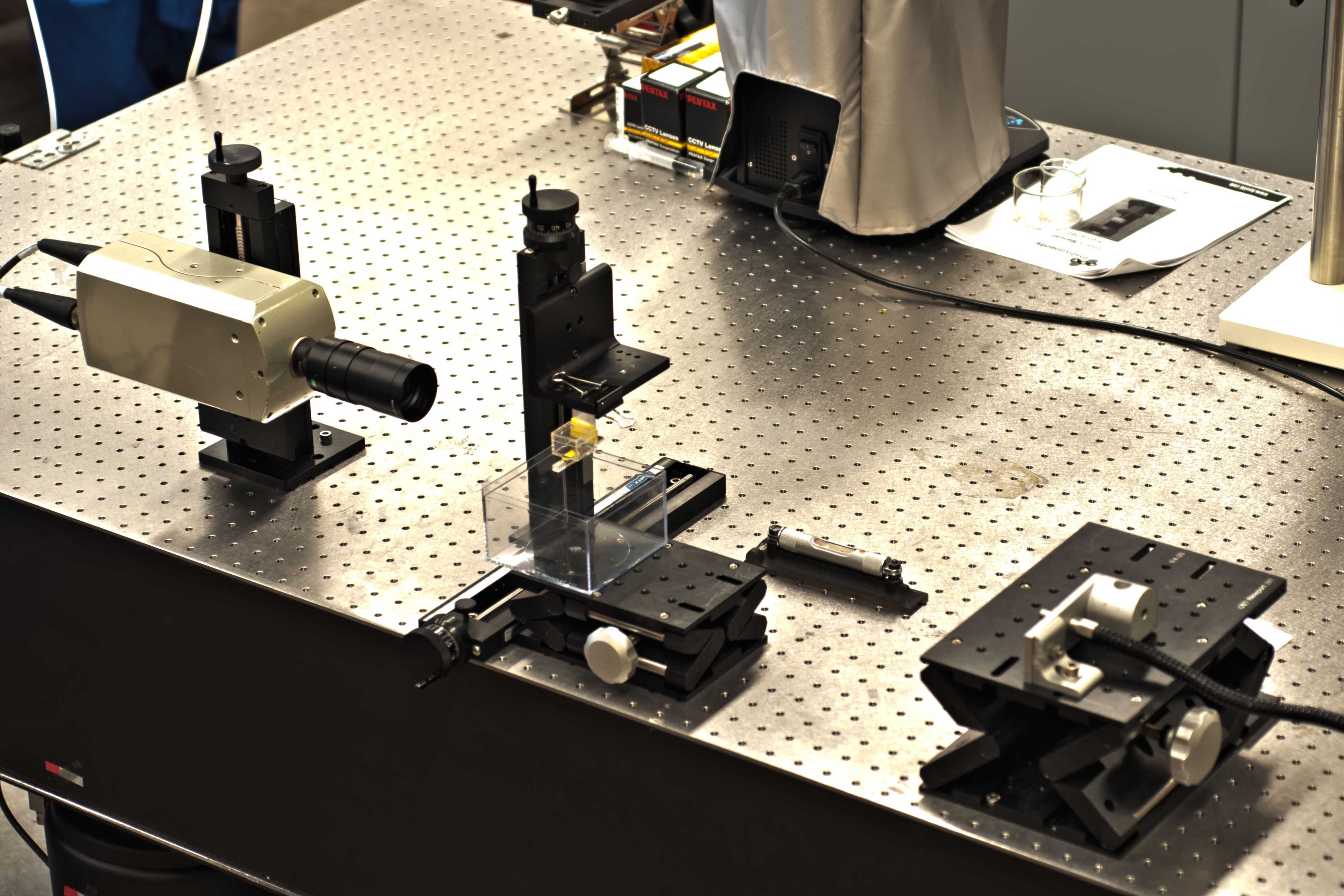
Figure 4 shows an annotated schematic and photograph of the experiment setup. Hardware for the experiments include a high speed camera, parallel light source, fluid reservoir, precision lab jack, vibration isolation table, and tubes with nozzles machined into acrylic blocks. The machined acrylic block is suspended above the fluid reservoir that sits on top of the lab jack. The jack is slowly raised toward the cylindrical capillary pores. Video footage shows the liquid make contact with the block, wick along the base of the block, rise up the pores, accelerate through the nozzles, and auto-eject.
3.3 ISS experiments
Figure 5 shows an annotated schematic and photograph of the experiment setup used by United States Astronaut Don Pettit who demonstrated auto-ejection of water aboard the ISS. The demonstration includes a polymer sheet tube, a piece of paper, a camera, and a wire loop. The video footage shows Pettit slowly bringing the tube into contact with the spherical reservoir and the ensuing capillary ‘rise’ and auto-ejection. The water droplet ejected aboard the ISS is times larger than the droplet ejected in the terrestrial experiment.

4 Results
Figure 6 is a map for auto-ejection in terms of parameters modified Suratman number and modified Weber number . Table 1 is the legend for Figure 6. Experiments show fair agreement with the scaling arguments as ejection primarily occurs when and is essentially absent for .
| Symbol | Meaning |
|---|---|
| 0 droplets ejected | |
| 1 droplet ejected | |
| 2 droplets ejected | |
| droplets ejected | |
| cS | |
| cS | |
| cS | |
| cS | |
| cS | |
| cS |
5 Additional Footage Explained
The video footage shows a single drop tower experiment illustrating the variety of auto-ejection possibilities. Four ID tubes partially submerged in 0.65cS PDMS with four different nozzles auto-eject jets (which break up into 6, 4, and 2 droplets) and a single droplet.
To illustrate repeatability the video shows 10 experiments of nearly identical conditions side by side. A ID tube with a ID nozzle is partially submerged in a 5cS PDMS reservoir. The ejected drop volumes from each experiment are .
The video concludes with a montage of sample applications of the auto-ejection technique. The first three clips show a cartridge with a 10 x 10 array of 5mm tubes partially submerged in test liquid. The clips show auto-ejected drops shoot up into the air, impact a flat smooth surface (rebounds abound), and impact a textured surface designed to capture and hold the droplets. Work is continuing in this direction.
To illustrate how auto-ejection is viable for droplet combustion experiments, a fourth clip shows an asymmetric u-tube with a nozzle pointed horizontally at a candle. The flammable 0.65cS PDMS liquid rises in the smaller tube with the higher curvature pushing a column of fuel vapor ahead of it. The candle back-ignites the combustible vapor and the flame resides at the nozzle exit. The spontaneously ejected droplets that follow ignite and fly through the air leaving a trail of soot behind them. One drop is small enough to self-extinguish.
6 Conclusion
Contrary to conventional wisdom, capillarity-driven droplet ejection is possible, predictable, repeatable, and a viable method for drop-on-demand delivery requirements for further capillary fluidic research. The video shows only a few of the many examples of potential applications for auto-ejection. The technique described herein can be used as a means to study drop formation, drop to jet transition, jet breakup, and droplet combustion at larger characteristic lengths then are achievable at 1. Droplet impact, splash, rebound, satellites, adhesion and coalescence are ripe fields that could benefit from this approach.
References
- [1] R. Siegel. Transient capillary rise in reduced and zero gravity fields. Journal of Appl. Mech, 83:165–170, 1961.
- [2] P.G. De Gennes, F. Brochard-Wyart, and D. Quéré. Capillarity and wetting phenomena: drops, bubbles, pearls, waves. Springer Verlag, 2004.
- [3] Andrew Wollman. Capillary-driven droplet ejection. Master’s thesis, Portland State University, July 2012.
- [4] Andrew Wollman and Mark M. Weislogel. New investigations in capillary fluidics using a drop tower. Experiments in Fluids, 2012. (in preperation).
- [5] M. Stange, M.E. Dreyer, and H.J. Rath. Capillary driven flow in circular cylindrical tubes. Physics of fluids, 15:2587, 2003.