Observation of the Larmor and Gouy Rotations with Electron Vortex Beams
Abstract
Electron vortex beams carrying intrinsic orbital angular momentum (OAM) are produced in electron microscopes where they are controlled and focused using magnetic lenses. We observe various rotational phenomena arising from the interaction between the OAM and magnetic lenses. First, the Zeeman coupling, proportional to the OAM and magnetic field strength, produces an OAM-independent Larmor rotation of a mode superposition inside the lens. Second, when passing through the focal plane, the electron beam acquires an additional Gouy phase dependent on the absolute value of the OAM. This brings about the Gouy rotation of the superposition image proportional to the sign of the OAM. A combination of the Larmor and Gouy effects can result in the addition (or subtraction) of rotations, depending on the OAM sign. This behaviour is unique to electron vortex beams and has no optical counterpart, as Larmor rotation occurs only for charged particles. Our experimental results are in agreement with recent theoretical predictions.
pacs:
42.50.Tx, 41.85.-p, 03.65.VfIntroduction.—In 1890, L. G. Gouy discovered the phase anomaly of a focused electromagnetic beam going through the focal point Gouy1890 . He showed that the converging Gaussian wave acquires a longitudinal phase delay with respect to a plane wave traveling the same distance. Since then, the Gouy phase ( is the waist plane and is the Rayleigh distance) has been a subject of interest, including fundamental classical and quantum interpretations Boyd1980 ; Visser2010 ; Subbarao1995 ; Feng2001 and direct observations in short pulses Ruffin1999 . In the past decade, the Gouy phase was observed for acoustic Holme2003 , phonon-polariton Feurer2002 , and surface plasmon Zhu2007 waves. It was also discussed for matter waves Paz2011 , although has been never observed directly. The Gouy phase plays an important role in the evolution of optical vortex beams Allen1992 carrying azimuthal phase, , and intrinsic orbital angular momentum (OAM) per photon: It is used in cylindrical-lens convertors Allen1992 ; Schattschneider2012 and is observed in the rotational propagation dynamics of vortex superposition patterns Basistiy1993 ; Arlt2003 ; Philip2012 .
Few years after the Gouy discovery, J. Larmor described the electron behaviour in a magnetic field and introduced the Larmor frequency Larmor , where and are the electron charge and mass, respectively. This frequency characterizes coupling between the electron angular momentum and the field. Although a classical electron orbiting in a magnetic field is described by the cyclotron frequency , it is the Larmor frequency that plays the fundametal role in the angular momentum conservation Brillouin , Zeeman effect Born , and structure of quantum Landau levels Fock .
Surprisingly, the seemingly unrelated optical Gouy and electron Larmor effects both become relevant in the evolution of electron vortex beams with intrinsic OAM in a magnetic field. Recently, such free-space beams were described Bliokh2007 and generated in transmission electron microscopes (TEM) Uchida2010 ; Verbeeck2010 ; McMorran2011 . They sparked interest for their potential for several applications, ranging from the study of magnetism on the atomic scale to high-energy particle collisions EVs . This year, several authors considered the evolution of the electron vortex states in a uniform magnetic field Gallatin2012 ; Bliokh2012 ; Greenshields2012 . They all described a uniform Larmor rotation of the mode superpositions with zero net OAM along the field, which originates from the Zeeman couping between the vortex OAM and the field. At the same time, we have shown Bliokh2012 that a fine interplay of the Zeeman and Gouy phases for the electron states with non-zero OAM determines a structure of the Landau levels and nontrivial rotational dynamics of electron vortex superpositions in a magnetic field.
In this paper we experimentally study the dynamics of electron vortices and their superpositions in the magnetic field of a focusing lens in TEM. In contrast to the uniform-field case, where the Zeeman-Larmor and Gouy effects act simultaneously Bliokh2012 , in a lens field they operate at different scales and can be spatially separated: The Zeeman phase is gained inside the lens; while the Gouy phase is acquired near the waist plane of the beam. The Zeeman phase for vortices manifests itself as a field-dependent Larmor image rotation known in electron microscopy, while the Gouy phase causes an additional OAM-dependent rotation of vortex superpositions. By adjusting the defocusing and magnification parameters, we independently vary the Larmor and Gouy rotations which are added or subtracted from each other depending on the OAM sign.
Larmor rotation of the OAM-balanced superpositions.— We first consider the “OAM-balanced” superposition of two opposite-charge vortex modes:
| (1) |
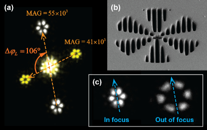
where is the vortex-beam wave function Allen1992 with , are the cylindrical coordinates, ( is the electron energy), and is the radial function slowly dependent on . The superposition (1) has zero OAM expectation value, , and is characterized by a “flower-like” symmetric pattern with radial petals Bliokh2012 ; Greenshields2012 : (see Fig. 1).
In practice, interfering two vortex beams is a difficult task. Instead, the desired superposition state can be obtained using holographic reconstruction through a computer generated hologram. A suitable mask is created by calculating the superposition (1) interfering with a tilted plane wave and applying a threshold to the interference pattern to obtain a binary distribution Greenshields2012 . The resulting mask obtained for is shown in Fig. 1b. We placed this mask aperture in the condenser plane of a Philips CM30 microscope operated at 300 kV and equipped with a field-emission gun. The illumination system of the TEM projected the wave, which holographically reconstructed the superpositions (1) in the first diffraction sidebands, in the front focal plane of the objective lens. Then we imaged the intensity profile of the beam in this plane through the imaging lenses of the microscope on a CCD camera (Fig. 1a).
Changing magnification, and hence the magnetic field in the imaging lenses, we observed a rotation of the images, as shown in Fig. 1a. This is a standard effect in electron microscopy where it is explained via classical cyclotron electron trajectories in a lens field. Remarkably, all these trajectories are focused on the conjugate plane, and the rotation between the object and its image is determined by the Larmor rotation of electrons with respect to the optical axis trajectories . However, it is difficult to explain all aspects of the image behaviour in a magnetic field via the classical trajectories. Indeed, in a uniform magnetic field, classical trajectories show either a cyclotron orbiting characterized by the frequency , or a rectilinear propagation along the field with . At the same time, the superposition (1) propagating along the field still obeys the Larmor rotation characterized by . This Larmor rotation of the OAM-balanced superposition image appears due to the quantum Zeeman phase difference between the vortex modes Bliokh2012 ; Greenshields2012 . Indeed, the Zeeman coupling energy between the OAM and magnetic field equals , which results in the additional phase
| (2) |
for a vortex mode in a magnetic field with varying magnitude . For the mode superposition (1), the difference of the Zeeman phases (2) produces the Larmor rotation of the image on the angle
| (3) |
We emphasize that while the barycenter of the image demonstrates cyclotron orbiting with repect to some axis and can be sensitive to the direction of the field, the orientation of the interference pattern always shows Larmor rotation with respect to its center, caused by the difference of the Zeeman phases (2) Bliokh2012 . In the lens field these two rotations yield the same Larmor angle (3) with respect to the optical axis trajectories , while in a uniform field the situation is more complicated Bliokh2012 .
We also focused and defocused the beam superposition (1) through the objective lens, thus imaging different planes of its propagation, but did not observe any rotation of the pattern (Fig. 1c). This confirmes that the OAM-balanced superpositions (1) do not acquire the Gouy phase difference Basistiy1993 ; Bliokh2012 .
Gouy rotation of superpositions with non-zero OAM.— Now we consider “unbalanced” superpositions with non-zero OAM. The simplest example is the vortex beam , but it has cylindrically-symmetric intensity and no rotation can be observed in the image. This can be overcome by creating a defect that breaks the cylindrical symmetry of the beam Arlt2003 . Blocking part of the beam creates a “C-shaped” (truncated) vortex beam:
| (4) |
where is the aperture stop position and is the angular sector cut of the vortex. The beam (4) still has the OAM expectation value per particle remark , but now it represents a superposition of many vortex modes which interefere with one another leading to complex diffraction deformations.
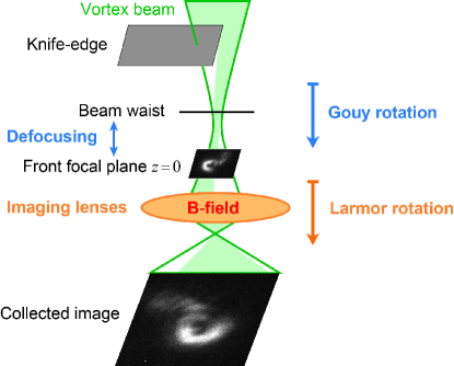
In our experiment (schematically shown in Fig. 2), we produced vortex beams with different using diffraction on a fork holographic aperture in the condenser plane of the microscope Verbeeck2010 ; McMorran2011 . Then we blocked half of one chosen beam using a sharp knife-edge aperture placed above the front focal plane of the objective lens, which corresponds to Eq. (4) with . We also used the condenser lens to focus and defocus the truncated vortex beam, effectively moving its waist with respect to the front focal plane of the imaging lens (Fig. 2). This allowed us to image different planes of the beam propagation and study the free-space diffraction effects (small variations in the condenser-lens field do not produce noticeable Larmor rotation).
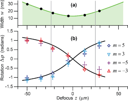
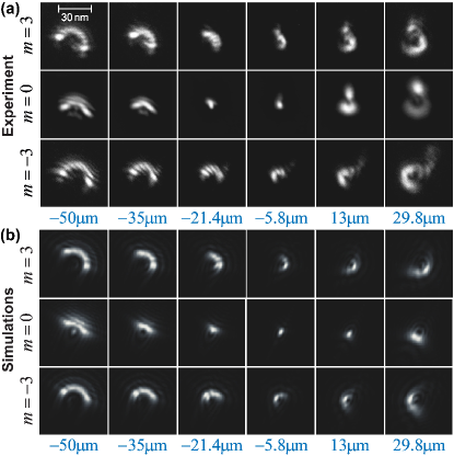
Figure 3a shows images of the evolution of the truncated vortex beams (4) with different at different planes as the beam propagates through its waist. One can observe the rotation of the C-shaped patterns in the direction determined by . On the one hand, this is explained by the azimuthal vortex current which transports the intensity distribution Arlt2003 ; Bekshaev2011 . On the other hand, this rotation is produced by the interference of the constituting OAM eigenmodes acquiring different Gouy phases. Indeed, the Gouy phase of the free-space Laguerre-Gaussian beam is equal to Allen1992
| (5) |
where is the radial mode number, corresponds to the waist position, and is the Rayleigh length ( is the beam waist). One can see that the propagation of a superposition of the OAM modes with the same and brings about a Gouy rotation of the interference pattern on the angle
| (6) |
In fact, the beam (4) contains many OAM modes with different and , which causes distortions of its shape upon the propagation (Fig. 3). Nonetheless, the orientation of the C-shaped patterns of the beams (4) with basically follows the Gouy rotation (6). (The beam does not rotate but “passes” instead trough the center.) Figure 3b shows numerical simulations of the free-space diffraction of the truncated vortex beams (using experimental values of the parameters), which appears to be in good agreement with experimental results of Fig. 3a.
In Fig. 4 we plotted the experimentally-measured angles of rotation for the beams (4) with different versus the defocus distance , compared to the theoretical Gouy dependence (6). In fact, in our setup, the beams were not exactly Gaussian but rather converging spherical waves. In this case the Gouy phase shows a different behaviour, which nevertheless approaches the arctan behaviour for trajectories close to the intensity maxima Visser2010 .
Combination of the Larmor and Gouy effects.— We have previously shown Bliokh2012 that for nondiffracting beams in a uniform magnetic field the Zeeman and Gouy phases appear simultaneously, and the OAM-carrying state would show, depending on the OAM sign, either no rotation, or a cyclotron rotation with , which is intimately related to the Landau-level properties. For diffracting beams in a TEM, however, the picture is rather different, and the Larmor and Gouy effects are spatially separated and practically uncoupled of each other (Fig. 2). The Gouy phase is gained near the beam waist at the front focal plane of the objective; it has the characteristic scale of the Rayleigh length , which is typically . At the same time, the Zeeman phase has the characteristic Larmor length, , which is typically –. In our setup the Gouy and Larmor rotations are tuned independently through the illumination and projective lenses remark2 .
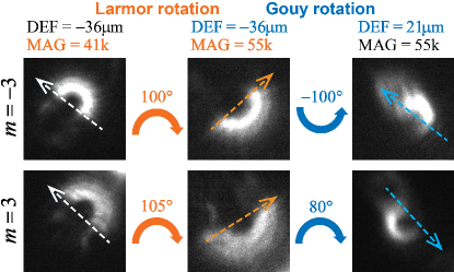
In Fig. 5 we show an experiment where the Gouy-phase rotation due to the defocusing (Figs. 2–4) was combined with the Larmor rotation produced by changing the magnification (Fig. 1). The parameters were chosen such that the two rotations have the same magnitude, , but the Gouy rotation also depends on the OAM sign. As a result, the negative-OAM truncated beam remained non-rotating, , while the positive-OAM beam rotated by the double angle .
Conclusion.— We have presented the first experimental demonstration of the Gouy phase for quantum matter waves, and explored the Zeeman-Larmor rotation of electron vortex superpositions. These two effects are uncoupled for the focused electron beams in typical lens fields. The OAM-dependent Zeeman phase produces an OAM-independent Larmor rotation, while the OAM-sign-independent Gouy phase results in the sign-dependent Gouy rotation. Therefore, the two effects can be added or subtracted from each other depending on the OAM sign. Such non-trivial dynamics of complex quantum electron states in a magnetic field is in contrast to the uniform cyclotron orbiting of classical electrons and to the magnetic-field-independent behaviour of optical vortex beams. On the one hand it is intimately related to fundamental quantum features such as the formation of Landau levels Bliokh2012 . On the other hand, these results might produce novel applications in electron microscopy, where the simulation and interpretation of micrographs and diffraction patterns has traditionally ignored the presence of phase singularities.
Acknowledgements.
G.G. and J.V. acknowledge funding from the European Research Council under the 7th Framework Program (FP7), ERC Starting Grant no. 278510 VORTEX. J.V. also acknowledges funding from the European Research Council under the 7th Framework Program (FP7), ERC Grant no. 46791-COUNTATOMS. P.S. acknowledges support of the Austrian Science Fund under grant I543-N20. K.B. and F.N. are partially supported by the European Commission (Marie Curie Action), ARO, JSPS-RFBR contract No. 12-02-92100, Grant-in-Aid for Scientific Research (S), MEXT Kakenhi on Quantum Cybernetics, and the JSPS via its FIRST program.References
- (1) C. R. Gouy, C. R. Acad. Sci. Paris 110, 1251 (1890).
- (2) R. W. Boyd, J. Opt. Soc. Am. 70, 877 (1980).
- (3) T. Visser and E. Wolf, Opt. Commun. 283, 3371 (2010).
- (4) R. Simon and N. Mukunda, Phys. Rev. Lett. 70, 880 (1993); D. Subbarao, Opt. Lett. 20, 2162 (1995).
- (5) P. Hariharan and P. A. Robinson, J. Mod. Opt. 43, 219 (1996); S. Feng and H. G. Winful, Opt. Lett. 26, 485 (2001).
- (6) S. Feng, H. G. Winful, and R. W. Hellwarth, Opt. Lett. 23, 385 (1998); A. Ruffin et al., Phys. Rev. Lett. 83, 3410 (1999); R. W. McGowan, R. A. Cheville, and D. Grischkowsky, Appl. Phys. Lett. 76, 670 (2000); F. Lindner et al., Phys. Rev. Lett. 92, 113001 (2004).
- (7) N. C. R. Holme et al., Appl. Phys. Lett. 83, 392 (2003); A. A. Kolomenskii, S. N. Jerebtsov, and H. A. Schuessler, Opt. Lett. 30, 2019 (2005).
- (8) T. Feurer et al., Phys. Rev. Lett. 88, 257402 (2002).
- (9) W. Zhu, A. Agrawal, and A. Nahata, Opt. Express 15, 9995 (2007).
- (10) I. G. da Paz et al., New J. Phys. 13, 125005 (2011); I. G. da Paz et al., Phys. Lett. A 374, 1660 (2010).
- (11) L. Allen et al., Phys. Rev. A 45, 8185 (1992); L. Allen, M. Padgett, and M. Babiker, Prog. Opt. 39, 291 (1999); Optical Angular Momentum, edited by L. Allen, S. M. Barnett, and M. J. Padgett (Taylor & Francis, London, 2003).
- (12) P. Schattschneider, M. Stöger-Pollach, and J. Verbeeck, Phys. Rev. Lett. 109, 084801 (2012).
- (13) I. V. Basistiy, V. Y. Bazhenov, M. S. Soskin, and M. V. Vasnetsov, Opt. Commun. 103, 422 (1993); S.M. Baumann, D.M. Kalb, L.H. MacMillan, and E.J. Galvez, Opt. Express 17, 9818 (2009).
- (14) J. Arlt, J. Mod. Opt. 50, 1573 (2003); J. Hamazaki, Y. Mineta, K. Oka, and R. Morita, Opt. Express 14, 8382 (2006); H. X. Cui et al., J. Opt. 14, 055707 (2012).
- (15) G. M. Philip, V. Kumar, G. Milione, and N. K. Viswanathan, Opt. Lett. 37, 2667 (2012).
- (16) J. Larmor, Aether and Matter (Cambridge University Press, 1900).
- (17) L. Brillouin, Phys. Rev. 67, 260 (1945).
- (18) M. Born, Atomic Physics (Dover, 1989).
- (19) V. Fock, Z. Physik 47, 446 (1928); C. G. Darwin, Math. Proc. Cambridge Phil. Soc. 27, 86 (1931).
- (20) K. Bliokh, Y. Bliokh, S. Savel’ev, and F. Nori, Phys. Rev. Lett. 99, 190404 (2007).
- (21) M. Uchida and A. Tonomura, Nature 464, 737 (2010).
- (22) J. Verbeeck, H. Tian, and P. Schattschneider, Nature 467, 301 (2010).
- (23) B. J. McMorran et al., Science 331, 192 (2011).
- (24) J. Verbeeck et al., Appl. Phys. Lett. 99, 203109 (2011); P. Schattschneider and J. Verbeeck, Ultramicroscopy 111, 461 (2011); I. P. Ivanov, Phys. Rev. D 83, 093001 (2011); K. Bliokh, M. R. Dennis, and F. Nori, Phys. Rev. Lett. 107, 174802 (2011); S. Lloyd, M. Babiker, and J. Yuan, Phys. Rev. Lett. 108, 074802 (2012); E. Karimi, L. Marrucci, V. Grillo, and E. Santamato, Phys. Rev. Lett. 108, 044801 (2012); P. Schattschneider et al., Ultramicroscopy 115, 21 (2012); P. Schattschneider et al., Phys. Rev. B 85, 134422 (2012); J. Verbeeck, H. Tian, and A. Béché, Ultramicroscopy 113, 83 (2012); K. Saitoh et al., J. Electron. Microscopy 61, 171 (2012); Z. Mohammadi et al., Opt. Express 20, 15024 (2012); S. Löffler and P. Schattschneider, Acta Cryst. A 68, 443 (2012); H. L. Xin and H. Zheng, Microsc. Microanal. 18, 711 (2012).
- (25) G. M. Gallatin and B. J. McMorran, Phys. Rev. A 86, 012701 (2012).
- (26) K. Y. Bliokh, P. Schattschneider, J. Verbeeck, and F. Nori, Phys. Rev. X 2, 041011 (2012).
- (27) C. Greenshields, R. L. Stamps, and S. Franke-Arnold, New J. Phys. 14, 103040 (2012).
- (28) W. Glaser, Grundlagen der Elektronenoptik (Springer-Verlag, Wien, 1952); M. De Graef, Introduction to Conventional Transmission Electron Microscopy (Cambridge University Press, 2003).
- (29) The OAM of the C-shaped beam (4) is not purely intrinsic but also has an extrinsic contribution since the barycenter of the beam is shifted off the vortex axis.
- (30) A. Bekshaev, K. Y. Bliokh, and M. Soskin, J. Opt. 13, 053001 (2011).
- (31) The simultaneous Gouy and Larmor rotation predicted in Bliokh2012 for a uniform magnetic field is more difficult to achieve because of the extremely small Larmor effect over the accessible distances in TEM. Elsewhere, we report the observation of the coupled Gouy-Larmor effect.