Coherence and Raman sideband cooling of a single atom in an optical tweezer
Abstract
We investigate quantum control of a single atom in an optical tweezer trap created by a tightly focused optical beam. We show that longitudinal polarization components in the dipole trap arising from the breakdown of the paraxial approximation give rise to significant internal-state decoherence. We show that this effect can be mitigated by appropriate choice of magnetic bias field, enabling Raman sideband cooling of a single atom close to its three-dimensional ground state in an optical trap with a beam waist as small as nm. We achieve vibrational occupation numbers of and in the radial and axial directions of the trap, corresponding to an rms size of the atomic wavepacket of 24 nm and 270 nm, respectively. This represents a promising starting point for future hybrid quantum systems where atoms are placed in close proximity to surfaces.
pacs:
37.10.DeSingle atoms in “optical tweezer” traps Schlosser et al. (2001) are a promising resource for various applications in quantum science and engineering. They can be individually moved Beugnon et al. (2007), manipulated Yavuz et al. (2006); Jones et al. (2007), and read-out Fuhrmanek et al. (2011) in a manner similar to trapped ions. At the same time, they may be strongly coupled to photonic Alton et al. (2011); Vetsch et al. (2010), plasmonic Chang et al. (2009), or other solid-state systems Hunger et al. (2010); Hafezi et al. (2012); Rabl et al. (2006), opening a new frontier for the realization of quantum networks and hybrid quantum systems. These intriguing applications require trapping single ultra-cold atoms near surfaces at distances well below an optical wavelength. While this is challenging for ions Daniilidis et al. (2011), and magnetically trapped atoms Lin et al. (2004); Hunger et al. (2010), it is readily achievable with neutral atoms in optical dipole traps.
The collisional blockade regime Schlosser et al. (2001) of optical dipole traps is an attractive starting point for such experiments because it provides a simple way to load and tightly confine single atoms starting with only a conventional optical molasses. In several experiments, it has been found that the temperature of an atom loaded from a molasses into an optical dipole trap in the collisional blockade regime is in the range 30 K to 180 K Tuchendler et al. (2008); Vetsch et al. (2010); Yavuz et al. (2006); Gaëtan et al. (2009); Jones et al. (2007); Rosenfeld et al. (2008); Urban et al. (2009). This elevated temperature compared to free-space cooling has been identified as a limiting factor in many recent experiments, as the thermal motion reduces the coherence time Yavuz et al. (2006); Jones et al. (2007); Rosenfeld et al. (2008) and impedes full quantum control Tey et al. (2009); Urban et al. (2009). Moreover, lower temperatures and a reduction in the spatial extent of the atomic wavepacket are necessary to control the atom at sub-wavelength distances from a surface, or to implement proposed quantum gates using collisional interactions between two ground state atoms Dorner et al. (2005).
One major challenge to laser cooling and quantum control are polarization effects associated with the breakdown of the paraxial approximation in very tightly focused optical dipole traps. Vector light shifts arising from elliptical light polarization Corwin et al. (1999) are known to be a major obstacle to cooling and manipulating atoms in optical dipole traps. In the paraxial limit, the vector light shift can be eliminated by using a linearly polarized trapping beam. However, in the tightly focused regime, non-paraxial effects produce a longitudinal and spatially inhomogeneous polarization component near the focus that cannot be eliminated. The resulting state-dependent trapping potential leads to dephasing of internal state superpositions Kuhr et al. (2005) and fluctuating dipole force heating, which impairs internal state manipulation as well as laser cooling.
In this Letter, we present a detailed study of the longitudinal polarization component of dipole trap formed by a high numerical aperture lens, demonstrate how the undesirable effects arising from the longitudinal polarization can be partially compensated using a properly oriented magnetic bias field, and apply these results to perform Raman sideband cooling of a single atom. After cooling, the atom is in the ground state along the two radial directions (), and occupies just a few quantum states () in the axial trap direction. The corresponding rms size of the atomic wavepacket is given by the ground state length of 24 nm in the radial directions, and a thermal extent of 270 nm in the axial direction, which represents a hundred-fold reduction in spatial volume, and a reduction by in phase-space volume, over the starting conditions.
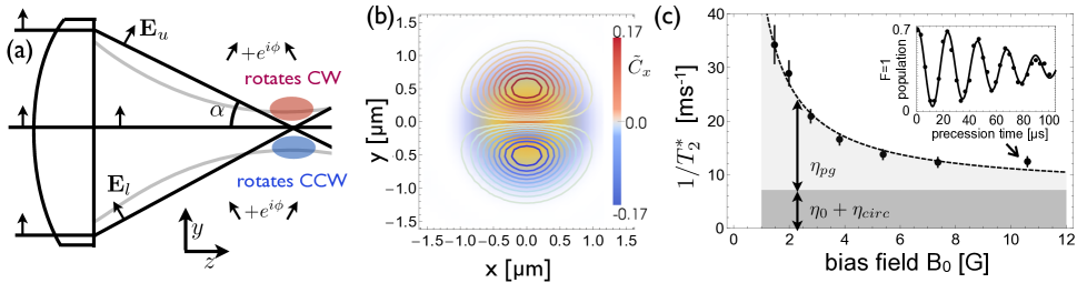
The origin and effects of the longitudinal polarization component can be understood in the framework of ray optics (see Figure 1a). The light entering a lens consists of parallel rays with linear polarization transverse to their propagation direction. Upon passing through the lens, rays are refracted according to their distance from the optical axis, and their polarization directions must also deflect to remain transverse to the ray Richards and Wolf (1959). In the diffraction-limited volume around the focus, all of these rays interfere and the resulting field is elliptically polarized. Following Fig. 1a, two features of the polarization near the focus emerge: (1) the polarization vector is rotating in the plane set by the incident polarization vector and the optical axis, and (2) the sense of this rotation is opposite above and below the optical axis.
For light that is far-detuned compared to the excited-state hyperfine structure, the vector light shift for alkali atoms in the ground state is Corwin et al. (1999); Deutsch and Jessen (1998):
| (1) |
where is the scalar dipole trap potential, and are the detunings from the D1 and D2 lines, respectively, is the local (unit norm) polarization vector, is the total angular momentum operator and . The term is a basis-independent way of expressing the normal vector of the polarization ellipse and the degree of ellipticity (with magnitude for circularly polarized light; 0 for linear polarization). Using the vector Debye integral Richards and Wolf (1959), we have numerically computed the polarization near the dipole trap focus (Fig. 1b). The most important term is the polarization gradient . For a lens with numerical aperture , the maximum gradient, occurring at the beam focus, is well approximated by if the lens aperture is uniformly illuminated, and if the illumination is a Gaussian beam with a diameter equal to the lens aperture diameter.
In the experiments presented here, we use an optical dipole trap for 87Rb atoms operating at nm with a depth mK. Independent measurements of the depth and radial trap frequency ( kHz) allow us to extract a beam radius nm and an effective lens aperture . For these parameters, we expect m. Since the state-dependent potential in Equation (1) is linear in , it produces the same energy shifts as a magnetic field, and can also be expressed as an effective magnetic field gradient with magnitude G/m at the trap center. This gradient gives the trapping potential a significant state-dependent component.
Specifically, in the absence of an externally applied magnetic bias field, atoms in different magnetic sublevels experience trapping potentials that are displaced by , where is the difference in the magnetic moment between the two sublevels. For , nm, which is not negligible compared to the ground state length nm. While this state-dependent displacement could be useful for Raman cooling or other motional state manipulations along this axis Förster et al. (2009); Li et al. (2012), it also leads to rapid internal-state decoherence on the timescale of the radial trap oscillation period.
To circumvent this problem, we can apply a bias magnetic field in a direction orthogonal to . In this case, the effective field gradient is suppressed since , and the gradient results in only a state-dependent change in the strength of the harmonic trap potential. Quantitatively, superpositions of magnetic sublevels that experience different trapping potentials of the form are dephased with a coherence time Kuhr et al. (2005), where is the temperature of the atom and is the Boltzmann constant. In the presence of a large orthogonal bias field, the polarization gradient contributes to as (the factor of 1/3 results from averaging over the three trap axes). We can use the dependence on to accurately measure , and also to suppress the dephasing with large .
We measure the decoherence between the states and using a sequence that starts with loading a single atom into a tweezer trap with a depth of 1.6 mK at zero bias field, then ramping down the trap depth to 0.82 mK as we ramp up the bias field to the desired value. The atom is optically pumped into , the hyperfine transition is driven by a two-photon Raman process in a Doppler-free configuration, and the state detection is accomplished using a push-out beam; these details are described in more detail below. is extracted from a Ramsey-type measurement, using a fit to the function introduced in Kuhr et al. (2005).
At each trap wavelength, we fit . The only free parameters in this fit are the degree of circular polarization in the incident dipole trap beam due to birefringence () and the strength of the effective field gradient . The temperature is determined independently (K for this measurement, see below for technique). reflects the different trapping potentials for and atoms due to the finite trap detuning, and is approximately given by the ratio of ground state hyperfine splitting to trap detuning. At a trap wavelength of (802,815) nm, we find m, corresponding to gradients m, in reasonable agreement with our estimate of 0.57 /m.
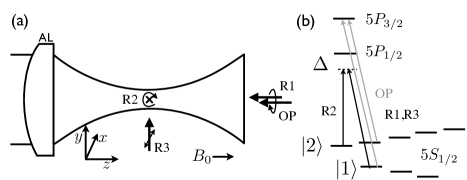
Having developed a detailed understanding of trap-induced decoherence in this system, we now turn to Raman sideband cooling. We use three orthogonal running-wave fields to drive Raman transitions (R1-R3, see Fig. 2a), as in trapped ion experiments Monroe et al. (1995); the different frequencies are generated by means of an electro-optic modulator Dotsenko et al. (2004). Optical pumping to the state is provided by circularly polarized beams propagating along the magnetic field axis, addressing the and transitions on the D2 line. The frequencies of the lasers are set to the measured resonances in the dipole trap, which are shifted by 30 MHz from the resonances in free space. The intensities of the two beams about 100 times less than saturation. This ensures that the atom only scatters photons elastically, so heating due to fluctuating dipole forces associated with the (anti-)trapping potential for the excited state is avoided Dalibard and Cohen-Tannoudji (1985). For diagnostic purposes, we measure the population by pushing out the atoms in using a beam resonant with the transition on the D2 line, then measuring whether the atom has remained trapped by turning the molasses back on. This beam is circularly polarized and propagates along the same path as the optical pumping beams.
In a typical experiment, we load an atom from the MOT into the optical dipole trap with a depth of 1.6 mK at zero bias field, then decrease the trap depth to 0.82 mK while ramping the bias field up to 7.5 G. Lowering the trap depth serves to increase the coherence time while leaving the trap frequencies high enough that sideband cooling is still achievable, with kHz. All temperatures reported in this paper are measured in the 0.82 mK deep trap. We cool the atoms in the following sequence: we first apply the R2 and R3 beams (Fig. 2) and the optical pumping beams together for 10 ms to continuously cool the radial modes; then, we perform ten cycles consisting of 2 ms of axial cooling using the R1 and R2 beams, followed by 4 ms of radial cooling using the R2 and R3 beams again. This sequence prevents the radial modes from heating while the axial cooling proceeds.
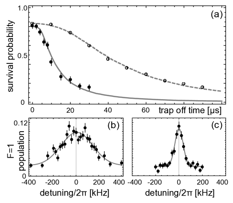
The parameters for the first radial cooling phase are optimized by measuring the temperature using a release and recapture technique Lett et al. (1988). This data, shown in Figure 3a, is fit using a Monte-Carlo simulation Tuchendler et al. (2008). The initial kinetic energy is such that K; the measurement after cooling yields anisotropic kinetic energies of K in the radial direction and K in the axial direction (the release and recapture technique is only weakly sensitive to the axial mode). The fitted kinetic energies represent the global minimum in over the entire space of three independent energies for each axis, including unphysical temperatures less than the ground state energy for the radial modes. The agreement of the measured kinetic energy with that of the zero-point motion suggests that we have reached the radial ground state after this cooling phase alone. The radial cooling works best with a two-photon Rabi frequency kHz and a detuning of kHz from the two-photon resonance, corresponding to , as expected.
To characterize the axial temperature independently after the radial cooling, we measure the Doppler width of the to transition when driven with the R1 and R2 beams. The wavevector has a projection onto the axial and radial directions, but the Doppler profile should mostly be sensitive to the axial mode here since the radial degrees of freedom are already cold. After the first stage of radial cooling, we measure a kinetic energy of K (Fig. 3b). After optimization, we obtain a feature with a width corresponding to K (Fig. 3c). This data is fitted to a Gaussian, which conservatively assumes no power broadening. The optimum cooling parameters are a two-photon Rabi frequency of kHz and a detuning of kHz. The parameters used for the interleaved radial cooling phases are the same as above.
To obtain more precise measurements of the final temperature of the atom, we resolve the asymmetric motional sidebands along two axes. The ratio of the sideband amplitude gives information about the vibrational state occupation of the atom Monroe et al. (1995).
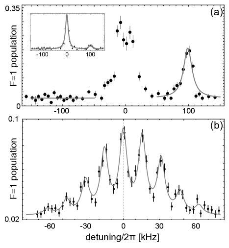
Figure 4a shows the sidebands measured in the radial direction with small . The blue sideband is essentially absent, with a fitted amplitude 100 times smaller than the red sideband. From this, we extract a final temperature for the radial degrees of freedom of . We do not know to what extent the two radial modes are non-degenerate or what the preferred axes are, but from the release-and-recapture data showing that both modes must be very cold, and the fact that the spectrum shown here does not change if we measure it at a different time after the cooling (up to 100 ms later), we infer that the two modes are not perfectly degenerate and the R2+R3 beams address both modes. Therefore, we conclude that this spectrum reflects the temperature of both radial modes.
We also resolve the axial motional sidebands using the R1 and R2 beams at very low power, and observe a spectrum with nine peaks that is slightly asymmetric (Fig. 4b). We find that the ratios of the measured peak heights correspond very well to a thermal distribution with a mean vibrational number . The corresponding energy K is similar to the result of the Doppler measurement above.
Several properties of the cooled atom are worth noting. The heating rate for the radial degrees of freedom is very low: we observe heating over 200 ms, which is consistent with what is expected from photon scattering only. We also do not observe radial heating if we translate the atom over distances m in ms using a scanning galvanometer mirror. Lastly, the fraction of atoms lost from our dipole trap ( 30 %) during the Raman cooling time (150 ms) is due entirely to background gas collisions ( torr), and not to the cooling process itself. We find that decreasing the Rabi frequency and detuning during the last cooling phase does not decrease the final axial temperature. This is possibly due to one of the following considerations: (1) in our apparatus, the R1+R2 beam pair couples motion along different axes, making it difficult to isolate the axial direction; (2) the ground state Lamb-Dicke factor is close to one on this axis (); and (3) the optical pumping beams are oriented along the axial direction, potentially causing extra heating which we have not characterized. At the same time, we are not aware of any fundamental effects that would prevent cooling to the ground state in this system.
We have quantified the coherence properties of single atoms subject to the polarization distortions present in tightly-focused and near-field optical dipole traps, and shown that the unwanted effects may be mitigated by applying a magnetic bias field in the appropriate direction. Using this result, we performed Raman sideband cooling of a single atom in an optical tweezer trap close to its ground state, achieving final mean occupation numbers . This technique should find immediate application to a variety of experiments using optical dipole traps.
We acknowledge funding from the NSF, CUA, DARPA, AFOSR, MURI and the Packard Foundation. JDT acknowledges support from the Fannie and John Hertz Foundation and the NSF GRFP.
Note After completion of this work, we have become aware of a related demonstration of Raman sideband cooling in an optical tweezer Kaufman et al. (2012).
References
- Schlosser et al. (2001) N. Schlosser, G. Reymond, I. Protsenko, and P. Grangier, Nature 411, 1024 (2001).
- Beugnon et al. (2007) J. Beugnon, C. Tuchendler, H. Marion, A. Gaëtan, Y. Miroshnychenko, Y. R. P. Sortais, A. M. Lance, M. P. A. Jones, G. Messin, A. Browaeys, et al., Nature Physics 3, 696 (2007).
- Yavuz et al. (2006) D. D. Yavuz, P. B. Kulatunga, E. Urban, T. A. Johnson, N. Proite, T. Henage, T. G. Walker, and M. Saffman, Physical Review Letters 96, 063001 (2006).
- Jones et al. (2007) M. P. A. Jones, J. Beugnon, A. Gaëtan, J. Zhang, G. Messin, A. Browaeys, and P. Grangier, Physical Review A 75, 4 (2007).
- Fuhrmanek et al. (2011) A. Fuhrmanek, R. Bourgain, Y. Sortais, and A. Browaeys, Physical Review Letters 106, 133003 (2011).
- Alton et al. (2011) D. Alton, N. Stern, T. Aoki, H. Lee, E. Ostby, K. Vahala, and H. Kimble, Nature Physics 7, 159 (2011).
- Vetsch et al. (2010) E. Vetsch, D. Reitz, G. Sagué, R. Schmidt, S. T. Dawkins, and A. Rauschenbeutel, Physical Review Letters 104, 203603 (2010).
- Chang et al. (2009) D. E. Chang, J. D. Thompson, H. Park, V. Vuletic, and M. D. Lukin, Physical Review Letters 103, 123004 (2009).
- Hunger et al. (2010) D. Hunger, S. Camerer, T. W. Haensch, D. Koenig, J. P. Kotthaus, J. Reichel, and P. Treutlein, Physical Review Letters 104, 143002 (2010).
- Hafezi et al. (2012) M. Hafezi, Z. Kim, S. L. Rolston, L. A. Orozco, B. L. Lev, and J. M. Taylor, Physical Review A 85, 020302 (2012).
- Rabl et al. (2006) P. Rabl, D. DeMille, J. Doyle, M. Lukin, R. Schoelkopf, and P. Zoller, Physical Review Letters 97, 33003 (2006).
- Daniilidis et al. (2011) N. Daniilidis, S. Narayanan, S. A. Moeller, R. Clark, T. E. Lee, P. J. Leek, A. Wallraff, S. Schulz, F. Schmidt-Kaler, and H. Haeffner, New Journal Of Physics 13, 013032 (2011).
- Lin et al. (2004) Y. Lin, I. Teper, C. Chin, and V. Vuletić, Physical Review Letters 92, 50404 (2004).
- Tuchendler et al. (2008) C. Tuchendler, A. M. Lance, A. Browaeys, Y. R. P. Sortais, and P. Grangier, Physical Review A 78, 9 (2008).
- Gaëtan et al. (2009) A. Gaëtan, Y. Miroshnychenko, T. Wilk, A. Chotia, M. Viteau, D. Comparat, P. Pillet, A. Browaeys, and P. Grangier, Nature Physics 5, 115 (2009).
- Rosenfeld et al. (2008) W. Rosenfeld, F. Hocke, F. Henkel, M. Krug, J. Volz, M. Weber, and H. Weinfurter, Physical Review Letters 101, 260403 (2008).
- Urban et al. (2009) E. Urban, T. Johnson, T. Henage, and L. Isenhower, Nature Physics 5, 110 (2009).
- Tey et al. (2009) M. K. Tey, G. Maslennikov, T. CH Liew, S. A. Aljunid, F. Huber, B. Chng, Z. Chen, V. Scarani, and C. Kurtsiefer, New Journal Of Physics 11, 043011 (2009).
- Dorner et al. (2005) U. Dorner, T. Calarco, P. Zoller, A. Browaeys, and P. Grangier, J. Opt. B: Quantum Semiclass. Opt. 7, S341 (2005).
- Corwin et al. (1999) K. Corwin, S. Kuppens, D. Cho, and C. Wieman, Physical Review Letters 83, 1311 (1999).
- Kuhr et al. (2005) S. Kuhr, W. Alt, D. Schrader, and I. Dotsenko, Physical Review A p. 023406 (2005).
- Richards and Wolf (1959) B. Richards and E. Wolf, Proceedings of the Royal Society A: Mathematical, Physical and Engineering Sciences 253, 358 (1959).
- Deutsch and Jessen (1998) I. H. Deutsch and P. S. Jessen, Physical Review A 57, 1972 (1998).
- Förster et al. (2009) L. Förster, M. Karski, J. Choi, A. Steffen, W. Alt, D. Meschede, A. Widera, E. Montano, J. Lee, W. Rakreungdet, et al., Physical Review Letters 103, 233001 (2009).
- Li et al. (2012) X. Li, T. Corcovilos, Y. Wang, and D. Weiss, Physical Review Letters 108, 103001 (2012).
- Monroe et al. (1995) C. Monroe, D. Meekhof, B. King, S. Jefferts, W. Itano, D. Wineland, and P. Gould, Physical Review Letters 75, 4011 (1995).
- Dotsenko et al. (2004) I. Dotsenko, W. Alt, S. Kuhr, D. Schrader, M. Muller, Y. Miroshnychenko, V. Gomer, A. Rauschenbeutel, and D. Meschede, Applied Physics B-Lasers And Optics 78, 711 (2004).
- Dalibard and Cohen-Tannoudji (1985) J. Dalibard and C. Cohen-Tannoudji, Journal Of The Optical Society Of America B-Optical Physics 2, 1707 (1985).
- Lett et al. (1988) P. Lett, R. Watts, C. Westbrook, W. Phillips, P. Gould, and H. Metcalf, Physical Review Letters 61, 169 (1988).
- Kaufman et al. (2012) A. M. Kaufman, B. J. Lester, and C. A. Regal, arXiv physics/atom-ph p. 1209.2087v1 (2012).