Design of Chemotaxis Devices Using Nano-Motors
Abstract
Several designs for micro-devices for chemotaxis based on nano-motors are proposed. The nano- or micro-motors are the conventional Janus rods or spheres that are powered by the catalytic reaction of fuels such as hydrogen peroxide. It is shown how these can be linked to make a device that can follow a concentration gradient of the fuel. The feasibility of assembling the devices using micromanipulation or metallic deposition is discussed. A possible design principle is suggested for a device that follows the concentration gradient of an analyte other than the fuel.
I Introduction
Chemotaxis is the movement of biological organisms in response to a chemical concentration gradient. Three things are required for the phenomenon: an ability to sense the gradient, a means of steering or orientation, and a means of propulsion. It is a challenge to modern micro-mechanical techniques to manufacture an artificial chemotaxis device on similar scales to those that occur in real organisms. One might imagine in the long term that such devices might play a role in targeted drug delivery or in chemical detection and localization. A first step on the long journey to such possible applications is the conceptual design of a micron sized chemotaxis device.
In recent years micro-motors have been manufactured in the form of Janus spheres or rods that differentially catalyze reactions at their surface. The solvent or solute provide the fuel, and the differential reaction is the basis of the propulsion mechanism. A common example is the catalytic decomposition of hydrogen peroxide, in which case both non-conducting (e.g. Pt/SiO2, Pt/TiO2) and conducting (e.g. Au/Pt) combinations have been used.Paxton05 ; Kline05 ; Ozin05 ; Howse07 ; Burdick08 ; Gibbs09 In the conducting case, the propulsion mechanism is thought to be electrokinetic.Moran11
One limitation of the artificial micro-motors that have been manufactured to date is that they have no method of sensing a concentration gradient or of aligning themselves with it. Although the propulsion force and hence the speed of the differential catalytic motors is proportional to the local concentration of fuel, this in itself does not provide directed motion because random Brownian impulses rapidly disorient the motor and there is no restoring mechanism to realign it in the preferred direction. Hence the motor follows a random walk through the solvent, with speed proportional to the local concentration of fuel, but with the velocity on average zero. Directional control has been achieved by using an external magnetic field and incorporating a ferromagnetic segment in the micro-motor,Kline05 ; Burdick08 but obviously as a model of chemotaxis it would be preferable if the steering mechanism could be based on the chemical concentration gradient itself.
The present note proposes some relatively simple designs that link differential catalytic micro-motors to achieve directional motion due to a chemical concentration gradient. The following section gives two designs for such chemotaxis micro-devices. In the third section, the feasibility of manufacture and other practical considerations are discussed.
II Chemotaxis Micro-Devices

Figure 1 is a sketch of a micro-motor. The convention used in this note is that the force on the motor is from the dark end to the light end, and hence the motion tends in the direction signified by the arrow. To be concrete, if the micro-motor was a Pt/Au Janus rod and the fuel was H2O2, then gold would be dark and platinum light. As mentioned in the introduction, the micro-motor has no preferred orientation and so it always travels in whatever direction its axis happens to be pointing irrespective of any concentration gradient. Random fluctuations frequently reorient the motor. The propulsive force is proportional to the local concentration. In practice the motor reaches a terminal speed in which the drag force is equal and opposite to the propulsive force. Typical dimensions of the motor are 2m long and 300 nm in diameter, and speeds can exceed 200m s-1.Moran11
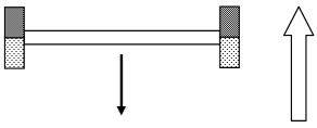
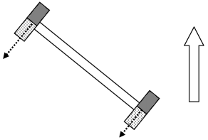
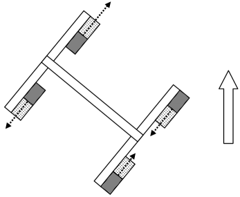
The basic concept for the chemotaxis devices is to use micro-motors to create a torque in the presence of a concentration gradient. The simplest such device is sketched in Fig. 2. (Practical issues regarding the manufacture and performance of the chemotaxis devices will be discussed in the following section.) The device consists of two parallel micro-motors, oriented perpendicular to a neutral lever arm and rigidly attached at the ends. It makes no difference whether the attached motors are Janus cylinders or spheres. In the orientation shown, the device moves against the concentration gradient, (i.e. from high concentrations to low), which is called negative chemotaxis. The reason for this particular arrangement is that it is stable to random fluctuations. For example, in Fig. 3 the device is rotated clockwise 45∘. Both motors create a propulsive force in the SW direction, but, due to the concentration gradient, the left motor experiences a higher concentration and hence creates a larger force. The consequent net turning moment on the couple acts in the counter-clockwise direction, which tends to restore the device to the original orientation.
For simplicity, in Fig. 2 the device is sketched in the plane of the page, and the discussion focussed on angular fluctuations within the plane of the page. In reality one has to be concerned with the orientation of the device in three dimensional space. The device as drawn in Fig. 2 would experience random twists about the long axis that would provide a stochastic contribution to its motion superimposed upon the deterministic negative chemotaxis. For full stability, one ought attach to the middle of the device in Fig. 2 an identical device oriented perpendicular to the page (all four motors parallel). Such an X-shaped device is stable with respect to all angular fluctuations.
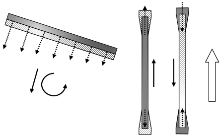
A limitation of the simple device sketched in Fig. 2 (and its three dimensional, cross-shaped analogue) is that it only performs negative chemotaxis. It is desirable to have the possibility of positive chemotaxis. This can be accomplished by using steering elements of the form shown in Fig. 4. A steering element consists of two antiparallel motors rigidly attached at the ends of a rod with which they are aligned. In the orientation shown, the elements move either with (positive chemotaxis, left element) or against (negative chemotaxis, right element) the concentration gradient. Even though the motors on each element oppose each other, due to the concentration gradient the motor at the higher concentration provides the larger propulsive force and hence the direction of motion. Neither steering element on its own has any reorientation ability and so the configuration shown is not stable.
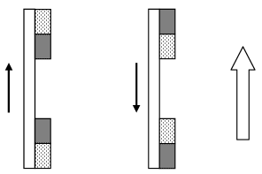
Joining the two types of steering elements with a rigid rod, as in Fig. 5, provides the necessary orientational stability. For example, in Fig. 6 a counter-clockwise 45∘ rotation creates a NE pointing force on the upper steering element, and a SW pointing force on the lower steering element, due to the way these elements have been designed to move in a concentration gradient. The coupling of these opposing forces gives a restoring clockwise torque on the device. As in Fig. 2, only the simplest planar configuration is shown explicitly here; full three dimensional stability can be obtained by attaching identical steering elements perpendicular to the page. To obtain motion (positive or negative chemotaxis), one can attach a motor with the desired orientation to the central rod.
III Practical Considerations
An important consideration is the size of the device. In general terms the larger the lever arm, the greater the torque, and hence the greater the orientation stability of the chemitaxis devices described above. However a larger lever arm also increases the drag, which reduces the terminal velocity.
The devices have been sketched above with micro-motors attached to the arms. Micro-manipulation techniques in the field of atomic force microscopy currently allow the routine gluing of colloidal spheres on the order of 10m in diameter to cantilevers on the order of 100m long (see, for example, Ref. Zhu11, and references therein). Micro-motors have currently been made in the form of rods 2m long and 300 nm in diameter,Paxton06 and in the form of 2m colloidal spheres.Gibbs10 Larger motors are likely easier to manufacture, and such small motors have only been pursued to date for reasons of buoyancy (see next) and for the kudos associated with achieving the smallest working micro-motor.
Since the motion of the micro-motors and of the chemotaxis devices occurs in three-dimensional liquid, it is important that the effects of gravity be minimised in order to avoid either sedimentation or flotation of the device during its motion. For the 2m motors mentioned above, the effects of gravity are small compared to the thermal fluctuations in the liquid, and buoyancy effects can be neglected over experimental time scales. In the case of the chemotaxis devices proposed here, micro-manipulation techniques demand somewhat larger micro-motors and lever arms, and one may possibly have to consider buoyancy effects. One solution is to choose connecting rods with positive buoyancy (e.g. polymer), such that in combination with the negatively buoyant attached motors the chemotaxis device is overall neutrally buoyant. One could also possibly attach negatively (e.g. tungsten) or positively (e.g. polymer) buoyant micro-spheres to the lever arms to achieve neutral buoyancy.
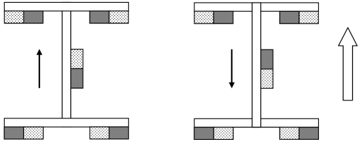
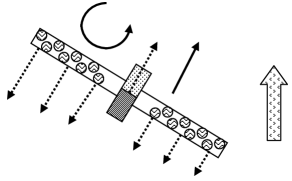
Alternatively, it might be possible to avoid the attachment step and to manufacture a smaller chemotaxis device by making the lever arms themselves the motors. This is illustrated in Fig. 7, where three elements for chemotaxis devices are shown. The elements could be made by metal evaporation and deposition, as has already been used to manufacture 2m spherical micromotors.Gibbs10 For the case of negative chemotaxis (left element, Fig. 7), the element is shown rotated from its stable position in order to indicate the restoring torque. It may be seen that it makes no conceptual difference whether the turning moment arises from a pair of motors attached at the ends of the lever arm, or from a continuum of motors distributed along its length. In the case of the steering elements it is imagined that the second metal can be deposited on top of the first at the ends of the rod, either by appropriate orientation of the rod, or by the use of shadow masks. It is not necessary that the entire rod be coated with the first metal.
Finally, although the devices proposed above can be expected to display chemotaxis, they suffer from a significant limitation, namely that the chemical used to power the motor is the same as that used to fix the orientation. In the real world, organisms that display chemotaxis respond to a given chemical via its concentration gradient, and their means of locomotion is quite independent of this stimulus. The next step in chemotaxis devices would be to separate these functions so that that motor fuel is different from the chemical gradient being followed.
Figure 8 sketches one possible design for a chemotaxis device that separates the functions of detection and locomotion. The idea is that a micro-motor attached to the center of a rod moves the device according to the concentration of the chosen propellent and is insensitive to any concentration gradients. Along the rod are distributed binding sites specific for the analyte of interest. It is assumed that this analyte binds reversibly to these sites, such that the fraction of occupied sites at any time depends on the local concentration of the analyte. It is further assumed that bound analytes increase the drag force on the rod, which may be reasonable for a polymer or biological macromolecule. These two design goals are undeniably challenging, but to the extent that they are satisfied, and with the addition of an identical arm perpendicular to the page, the device would have orientation stability, and it will display positive chemotaxis for the chosen analyte. Obviously there are many challenges in tuning the parameters to obtain a working device, but at least conceptually it illustrates one possible way that locomotion and steering can be separated in an artificial chemotaxis device.
References
- (1) W. F. Paxton, A. Sen, and T. E. Mallouk, Chem.-Euro. J. 11, 6462 (2005).
- (2) T. R. Kline, W. F. Paxton, T. E.Mallouk, and A. Sen, Angew. Chem. Intl Edn 44, 744 (2005).
- (3) G. A. Ozin, I. Manners, S. Fournier-Bidoz, and A. Arsenault, Adv. Mater. (Weinheim, Ger.) 17, 3011 (2005).
- (4) J. R. Howse, R. A. L. Jones, A. J. Ryan, T. Gough, R. Vafabakhsh, and R. Golestanian, Phys. Rev. Let. 99, 048102 (2007).
- (5) J. Burdick, R. Laocharoensuk, P. M. Wheat, J. D. Posner, and J. Wang, J. Amer. Chem. Soc. 130, 8164 (2008).
- (6) J. G. Gibbs and Y. P. Zhao, Appl. Phys. Let. 94, 163104 (2009).
- (7) J. L. Moran and J. D. Posner, J. Fluid Mech. 680, 31 (2011).
- (8) L. Zhu, P. Attard, and C. Neto, Langmuir, 27, 6712 (2011).
- (9) W. F. Paxton, P. T. Baker, T. R. Kline, Y. Wang, T. E. Mallouk, and A. Sen J. Am. Chem. Soc. 128, 14881 (2006).
- (10) J. G. Gibbs, N. A. Fragnito, and Y. Zhao, Appl. Phys. Lett. 97, 253107 (2010).