Status and performances of the FAZIA project
Abstract
FAZIA is designed for detailed studies of the isospin degree of freedom, extending to the limits the isotopic identification of charged products from nuclear collisions when using silicon detectors and CsI(Tl) scintillators. We show that the FAZIA telescopes give isotopic identification up to Z25 with a E-E technique. Digital Pulse Shape Analysis makes possible elemental identification up to Z=55 and isotopic identification for Z=1-10 when using the response of a single silicon detector. The project is now in the phase of building a demonstrator comprising about 200 telescopes.
1 Introduction
With the advent of exotic beams delivered by present and future accelerator facilities, it is a challenge for physicists to design detection arrays able to completely identify (atomic number and mass, energy) the nuclear reaction products, taking thus full advantage of these new beams. Indeed one of the present motivations for studying nuclear collisions is to improve the knowledge of the nuclear equation of state, and particularly of the density dependence of its symmetry energy term, Esym [1, 2, 3]. In this aim, at moderate and low energies, dissipative collisions induced by exotic projectiles should provide new information on the neck-instabilities, and on the achievement of isospin equilibration, both directly depending on Esym. In the same energy domain a study of the de-excitation properties of isotopic chains of compound nuclei, with complete isotopic identification of the emitted nuclei and of the final residue [4], will allow to test the N/Z dependence of the level density parameter; this will give unique information on the temperature dependence of Esym. Pushing CN towards the drip lines will permit to explore decay modes that cannot be predicted by the Weisskopf theory (clustering, multifragmentation) and thus to test the validity domain of the basic assumptions of that theory. With an increased knowledge of the de-excitation of hot nuclei, when going around the Fermi energy, thermodynamical properties of multifragmenting nuclear systems (excitation energy, caloric curves) should be more accurately determined [5, 6], providing more precise values of limiting temperatures. Measurements of fragment isotopic distributions should also permit to constrain Esym.
At present time, the most powerful 4 arrays suffer from several drawbacks. INDRA [7], is composed of Ionisation Chamber-Silicon-CsI(Tl) telescopes and uses E-E and light shape analysis to identify nuclei. It well identifies the atomic number of the charged products up to Z60, with a threshold of 1 MeV, but its isotopic identification is limited to Z=6. CHIMERA [8] is an ensemble of Silicon-CsI(Tl) telescopes which identifies nuclei through time of flight, E-E and light shape analysis techniques. It has very low thresholds for mass identification, but much higher ones for Z-identification. CHIMERA gives isotopic identification, Z and A, up to Z=13 [9]. Even specific correlators such as LASSA [10], based on E-E identification, have an isotopic separation only up to Z=9. The reader is sent to ref. [11] for a more exhaustive detector review. The unsurpassed nucleus identifiers are still spectrometers, which provide mass charge, energy and velocity of nuclei with a high resolution. They cover however a very small solid angle and cannot fully analyse many-body events, unless they are coupled to other detection arrays.
In this context a group of french and italian physicists studying nuclear dynamics and thermodynamics started, at the dawn of the century, a vigourous R&D aiming at obtaining isotopic identification up to mass 50 over a large solid angle. The main idea was to examine the detailed shape of the current signal created in a silicon detector by the passage of a charged particle, by sampling it with a fast ADC. This group later became the FAZIA Collaboration, which nowadays comprises about 60 physicists from France, Italie, Poland, Romania and Spain.
2 The FAZIA telescope
FAZIA is intended to work for studying reactions from the Coulomb barrier up to 100 MeV. It was thought as a 4 array comprising a large number (several thousands) of three-stage telescopes, two silicon detectors (Si1: 300 m and Si2: 500 m) followed by a CsI(Tl) scintillator readout by a photodiode. Gas detectors are avoided because of their mechanical size. The desired low identification thresholds are provided by pulse shape analysis (PSA) of the signals of the first silicon, with the help of time of flight measurement for very slow particles [12, 13]. In order to improve the performances of present arrays, a lot of work was performed on the response of CsI(Tl) scintillators and above all on that of silicon detectors.
2.1 Silicon detectors: the lessons of R&D
When one wants to use the shape of the signal created by a charged particle traversing a silicon detector of finite area, it is mandatory that the detector response be independent of the impact position. This implies that the field should be homogeneous in the bulk of the detector. An answer to this requirement is obtained by using n-type implanted silicon doped with phosphorus through neutron transmutation; this process provides silicon wafers with resistivity around 3000 .cm and resistivity fluctuations smaller than 4% FWHM (against 30% for standard silicon wafers). Another constraint is that particles must not cross the detector following a crystal axis or plane: as known for 50 years, detectors must be cut off-axis to avoid channeling effects which induce large fluctuations in the response to monoenergetic particles [14, 15]. Note that this constraint limits the angular aperture of a telescope; the FAZIA telescopes have a square area 22 cm2. They will be mounted between 1 and 1.2 m from the target. Finally the bias voltage on the detector is kept constant by permanently monitoring the reverse current and correcting the applied voltage.
We chose a reverse mounting so that particles enter through the low-field side of the detector, in order to maximize the shape differences between elements and isotopes [13]. However although in this last reference overbiasing detectors was recommended, we found that a better identification was obtained when using the detector depletion voltage, or even slightly less. A compromise has still to be found between shape discrimination and good timing for time of flight.
2.2 The CsI(Tl) scintillators
The scintillator length was fixed to 10 cm, to make FAZIA operational up to 100 MeV by stopping all light charged particles. Having such a length, the crystals are tapered to keep the same angular aperture at both ends. In order to favor scintillation efficiency for heavy ions, we chose a Tl concentration of 2000 ppm [16]. The light response and resolution, as well as its homogeneity along the detector length were improved by wrapping the crystals with a highly reflective material, 3M VikuityTM ESR [17]. The CsI(Tl) are coupled to 22 cm2 photodiodes.
2.3 Front-end electronics
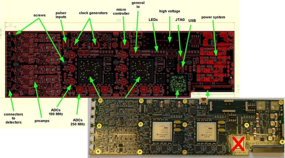
The Front End Electronics board of FAZIA, designed at IPN Orsay, houses all the necessary modules for complete processing of the three detector signals of two telescopes. The prototype version is represented in figure 1. The detectors are connected to the preamplifiers, located on the board, by kapton strips. The preamplifiers are derived from the PACI [18], without the current output; the current signal, I, is now obtained in the FEE board by analogically deriving the charge signal, Q. The gain on the charge output is 2 mV/MeV.
| \br | Q signal | I signal | |||
|---|---|---|---|---|---|
| \mrDetector | E range | sampling rate | resolution | sampling rate | resolution |
| \mrSi1 | 250 MeV | 250 Ms/s | 14 bits | 250 Ms/s | 14 bits |
| 4 GeV | 100 Ms/s | 14 bits | |||
| Si2 | 4 GeV | 100 Ms/s | 14 bits | 250 Ms/s | 14 bits |
| CsI(Tl) + PD | 4 GeV | 100 Ms/s | 14 bits | ||
| \br | |||||
Each signal is sent to a fast ADC (see table 1), apart from the Q signal of Si1 which is processed twice, with a high gain for light particles and fragments, and with a low gain for heavier ions, in order to improve PSA and Time of Flight in both cases (see sect. 3.1). Thus a FEE board comprises 62 14 bit ADC’s. The high voltages for the two silicon detectors are built up locally in the FEE card and are individually controlled (section 2.1); the card performs the voltage compensation due to reverse current. One FPGA is in charge of a preprocessing of all signals for each telescope. It stores and reads out the Q and I waveforms. It gives a zero-level trigger which signals that the telescope was hit. It then provides a precise value of the energy deposited in Si1, Si2 and CsI(Tl)+PD by means of trapezoidal filters. The FEE card also holds one pulser for linearity calibration purpose and clocks to synchronize the different signals. All information from the FPGA is transmitted to the acquisition system through a block card (section 4), the connector between both cards is visible on the low rhs of the photo.
3 Performances
3.1 Particle identification
We found that improving the qualities of the silicon detectors of the telescope also greatly enlarged the isotopic identification when using the E-E method for Si1 vs Si2 responses. Figure 3 shows that masses are separated for Z up to 23 with this technique. We have found isotopic identification on the same mass range when using the E-E method with (Si1+Si2) vs CsI(Tl) [19].
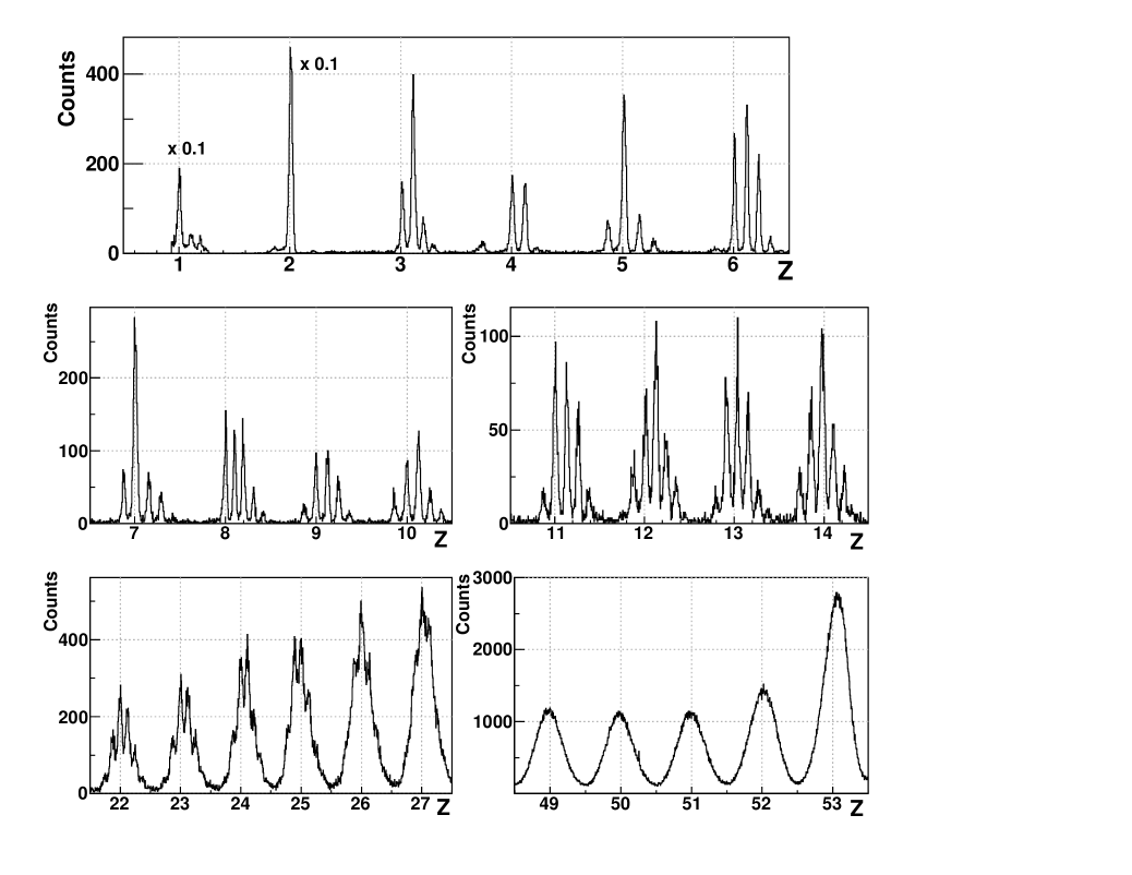
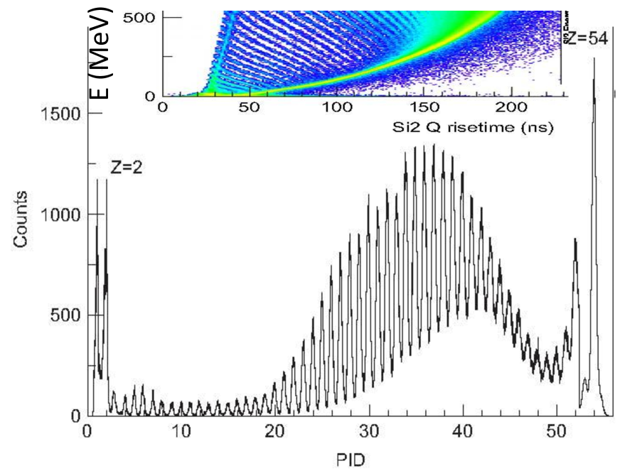
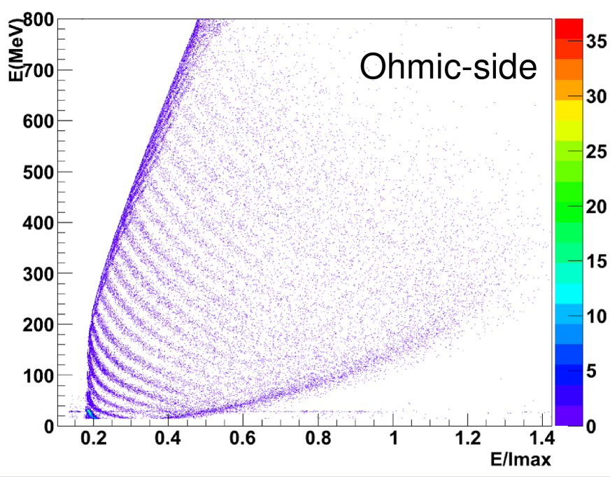
Identifying nuclei stopped in one silicon implies using two parameters provided by this single detector. One of these is the measured energy of a particle; for the second we chose either the rise time of the charge signal, , or the maximum amplitude of the current signals (Imax or E/Imax). The Particle IDentification (PID) data presented in figure 3 were obtained with a detector for which the latter method was more performant, and Z identification is observed up to Z=54 [19]; in that case we performed PSA on the second silicon, in which most of the produced nuclei were stopped. Indeed figures 3 and 3 were obtained with the same telescope detecting nuclei produced in 35 MeV 129Xe+124Sn reactions. The 306m second silicon111this telescope comprised two 300 m silicon, it was thus not a “standard” FAZIA telescope was exceptionnally good, having a resistivity = 3000 .cm with a FWHM of the distribution across the detector of 0.6% [20]; it was biased 3% above the depletion voltage. Figure 3 also shows that no mass identification is visible, even for the lightest elements. This is in disagreement with some of our results, where isotopes were seen for Z up to Z=7-8, see figure 5 and ref [15]. This discrepancy was attributed to the gain of the preamplifier, which was 3 times larger for the data of figure 5 than for those displayed in figure 3. This led us to adopt two gains for the coding of the energy signal of the first silicon detector of each FAZIA telecope.
3.2 Foreseen possible improvements
In view of possible developments aiming at an increased granularity, we have tested the PSA of the response of Double Sided Strip Silicon Detectors (DSSSD). The map displayed in figure 5 was obtained with a 500 m nTD silicon, with 16 strips on each side. Particles entered through the low-field (ohmic) side. Same results were obtained when taking signals from the P-side or the ohmic-side. The figure shows that elements are identified with resolution and range similar to those of the other detectors.
Another solution which is thought of, because if would save quite an amount of money for the 4 array, is to replace the FAZIA modules at backward angles (past 90o in the laboratory) by Single Chip Telescopes, SCT. This arrangement suppresses one electronic channel, because the silicon detector preceding the CsI(Tl) can be used both as a detector and as a photodiode for the scintillator light readout. SCT’s were tested during the FAZIA R&D and, using suitable algorithms, it was shown that performances comparable to those of a FAZIA telescope were obtained for H and He isotope identification, whereas they are not as good for light fragments, particularly at low energy [21]. For this reason SCT should be positioned at angles where only few and light fragments are emitted.
3.3 Energy identification thresholds
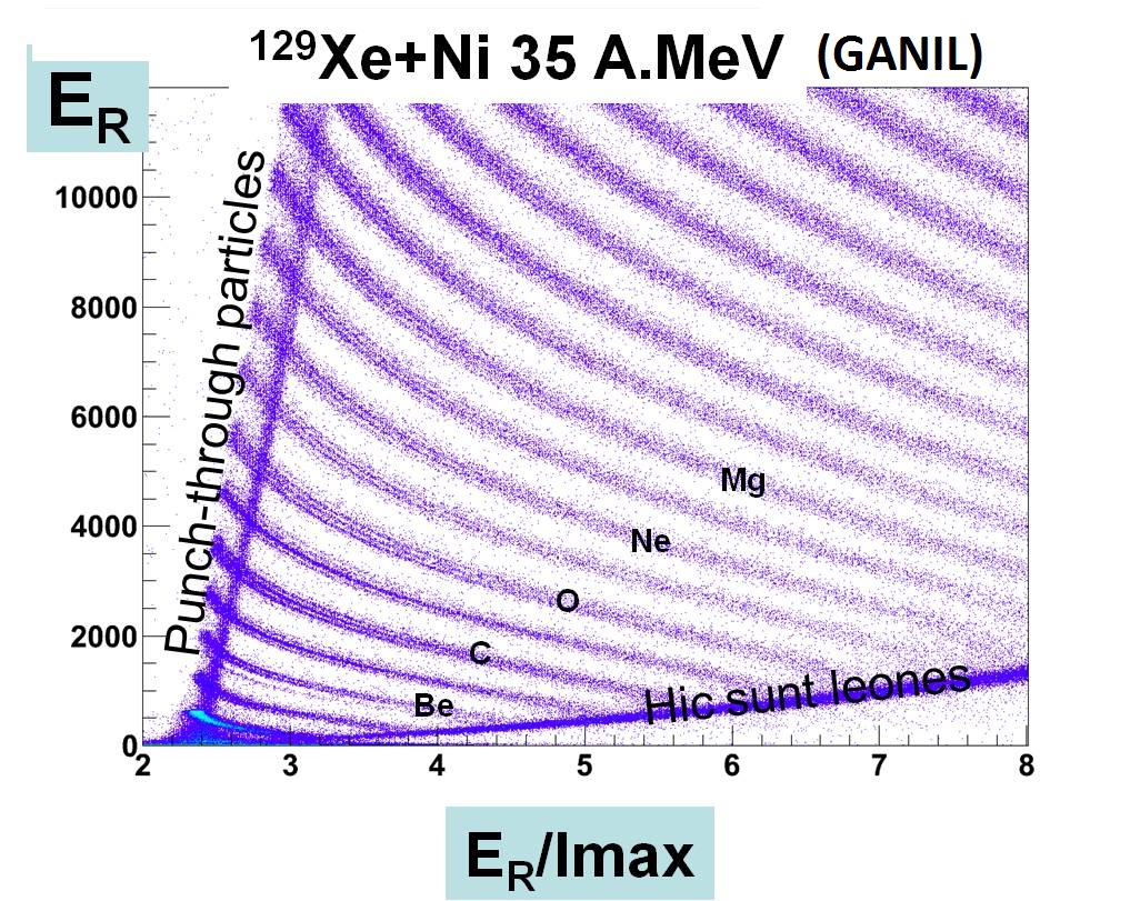
We can observe in the inset of figure 3, showing part of a E vs map, that at low energy nuclei can not be identified with a PSA method: all ridge lines converge into a single locus. We quantified the energy threshold for Z-identification, using a factor of merit, where are the average PID values for nuclei Z1 and Z2=Z1+1, and the are the full widths at half maximum of the PID peaks. Two elements are considered as well separated when 0.7.
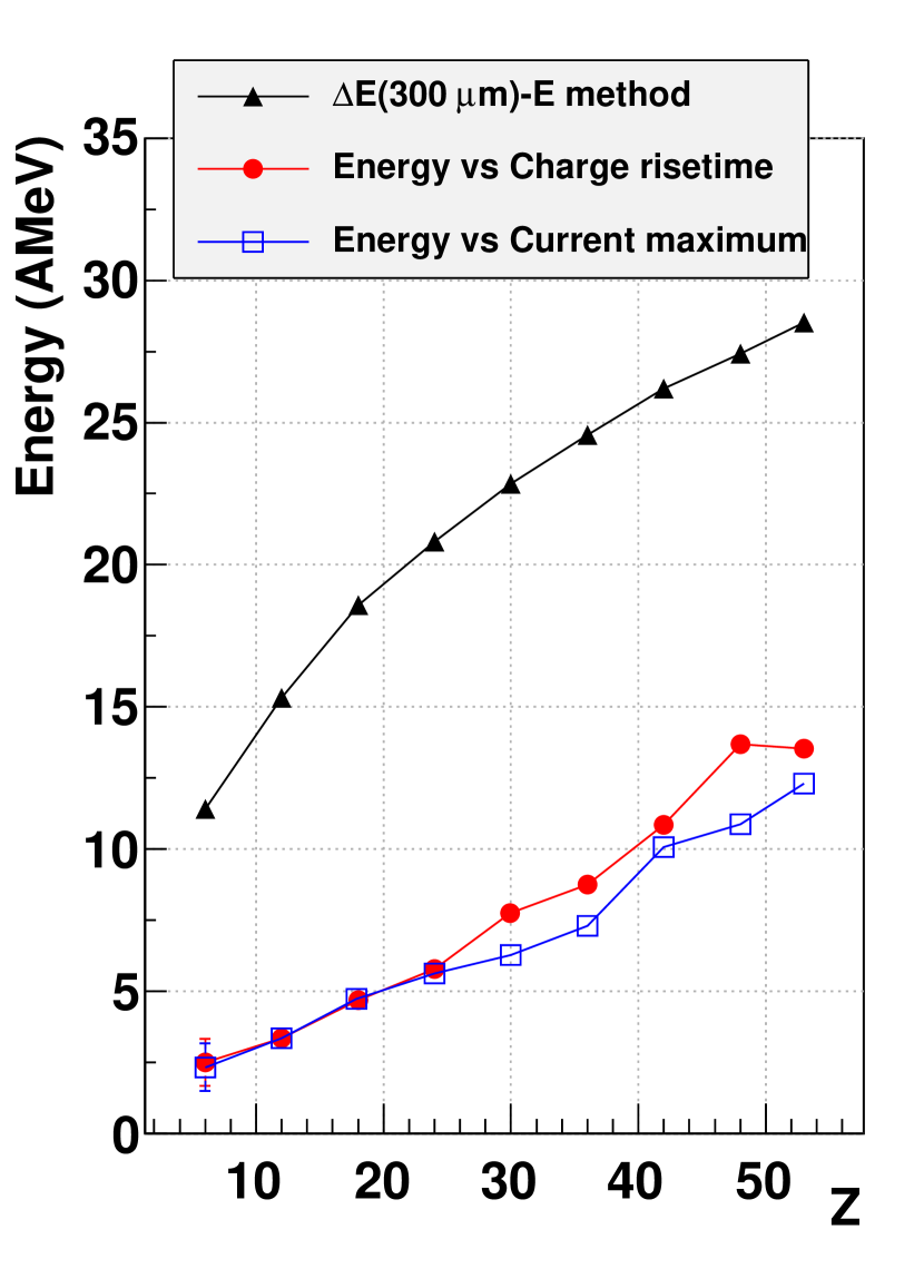
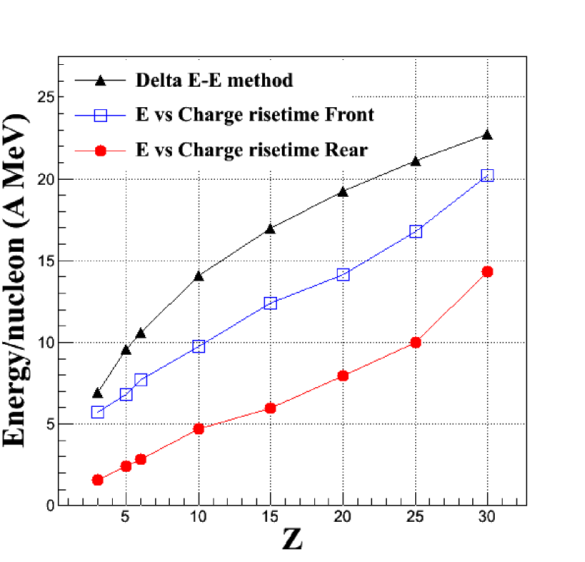
In figure 6 the thresholds so determined are plotted in several cases, and compared to those imposed by the punching-through of a 300 m silicon when using a E-E method. A general remark is that PSA does significantly lower the Z-identification thresholds. The left part of the figure corresponds to results obtained for the highly homogeneous silicon of figure 3, when particles enter the detector through the low field side. The two PSA methods, E vs and E vs Imax, give close thresholds, from 2 MeV for Z=6 to 6 MeV for Z=30 and 11 MeV for Z=50. The right part of the figure displays data obtained for a less homogeneous detector (4% -FWHM). In that case we compared the thresholds obtained, in the same conditions, when particles enter through the low or high field side [22]. We firstly note that much lower thresholds are measured when the detector is reverse mounted, confirming that this is the best choice when using PSA techniques. Second, if we compare the thresholds obtained for rear entrance in the two detectors (left and right pictures), we note the influence of the resistivity homogeneity: they are about 1.5-2.5 times lower for the -homogeneous detector.
3.4 The problem of radiation damages
As soon as silicon detectors started to be used, it was observed that the crystal structure, and thus the detector response, was degraded by the detected particles, particularly when very heavy ions stop in a detector. This raises problems when using silicon detectors with heavy beams, at angles where they detect the high rate elastic scattering events. Any degradation of the response of the detector becomes unacceptable when one makes use of pulse shape analysis. A specific study of the radiation damages was undertaken during our R&D, and we could reach quantitave conclusions. We irradiated a 300m silicon detector with 35 MeV Xe ions. Collimators and degraders allowed to define a zone in which the ions punch through the detector and a second one where the ions were stopped [23].
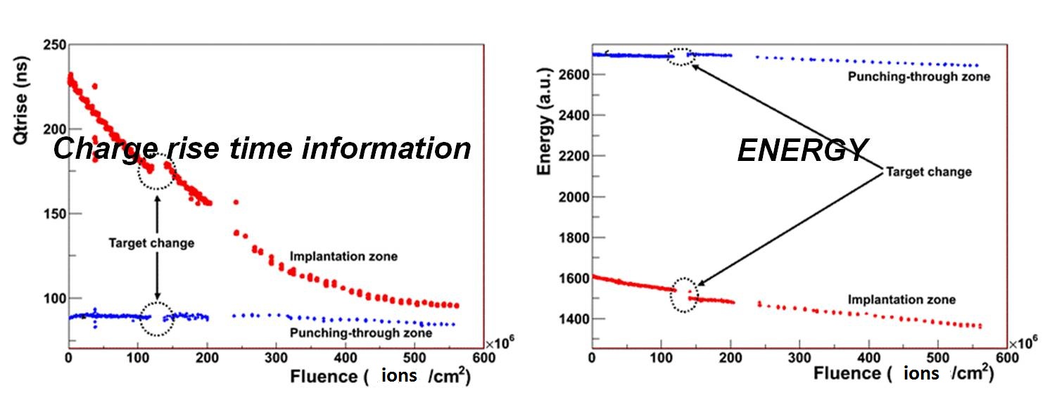
Up to 6108 ionscm2 ions hit the detector. Minor effects on the measured values of E and were observed when the Xe ions crossed the silicon. Conversely dramatic differences were found on both parameters when the ions stopped in the detector. At maximum fluence the energy has decreased by 20% whereas dropped by a factor 2.5.
These observations make delicate the use of very heavy ions for FAZIA experiments, particularly at low energy where the grazing angle is large. It would be interesting to test in the future if some annealing process could allow to recover acceptable functioning of the damaged silicon detectors.
4 FAZIA demonstrator
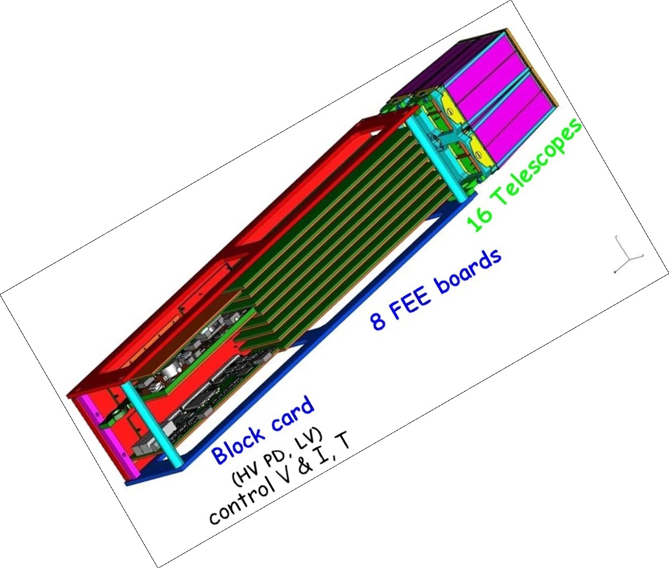
The FAZIA project is presently in the phase of building a demonstrator. This demonstrator will be an array of 192 telescopes arranged in 12 blocks of 16. The final (i.e. for the future 4 array) electronics and mechanical solutions are adopted. We feel useful to minimize the detector-preamplifier-digitizer distances, therefore the FEE is located inside the vacuum chamber222for all test results presented in the previous section, only the preamplifiers were in vacuum, implying several meters of differential cable between PA and FEE. The electronic arrangement is represented in figure 9. The 8 FEE boards necessary to treat the 16 telescopes are piled up and all connected to a single block card. The block card connects the FEE to the acquisition system by means of an optical fiber insuring the air-vacuum feed-through. Through this fiber it receives a 48 V voltage out of which it builds the photodiode high voltages and different low voltages which are transmitted to the FEE boards to generate the low voltages for preamplifiers and the high voltages for silicon detectors. It also houses one flash ADC to receive the accelerator RF signal which will be used for time of flight measurement. Due to the compacity of the electronics, an efficient cooling system is required; all FEE and the block cards lean on a copper plate in which circulates a water-antifreeze liquid.
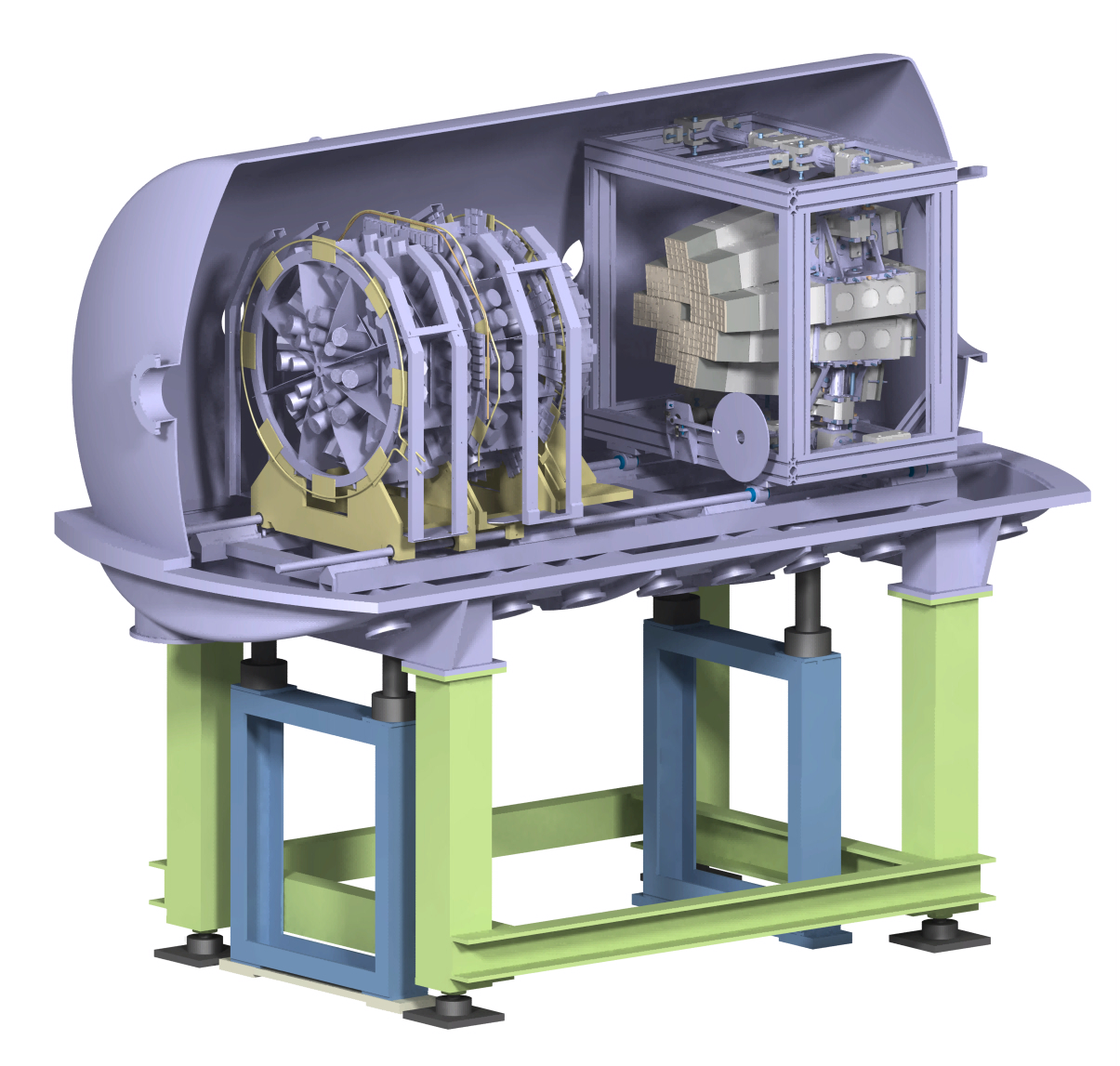
A completely equipped block will be tested at LNS (Catania) at the end of 2012. The demonstrator is expected to be ready in 2014. It will first be coupled to existing arrays such as INDRA (GANIL-SPIRAL2), CHIMERA (LNS-FRIBS), GARFIELD (LNL-SPES) in order to get new and improved physics results. The modularity of the blocks allows to mount them in different mechanical configurations, depending on the experiment. For instance dissipative collisions will be studied by arranging the blocks in a coplanar belt at intermediate angles. Other planes are to study fusion reactions between light nuclei. In that aim the 12 FAZIA blocks will replace the forward rings of INDRA, as shown in figure 9. See [24] for more details on some proposed letters of intent.
References
References
- [1] Baran V, Colonna M et al. 2005 Phys. Rep. 410 335–466
- [2] Bao-An Li, Lie-Wen Chen et al. 2008 Phys. Rep. 464 113–281
- [3] Rivet M F 2009 Lecture given at the Joliot-Curie school 2009 (Preprint http://hal.in2p3.fr/in2p3-00584498/fr/)
- [4] Marini P, Rivet M F et al. (INDRA collaboration) 2010 Proc. II Int. Workshop on Compound Nucleus Reactions vol 2 (EDP Sciences) p 04003
- [5] Viola V E and Bougault R 2006 Dynamics and Thermodynamics with nuclear degrees of freedom (Eur. Phys. J. A vol 30) ed Chomaz P, Gulminelli F et al. (Springer) pp 215–226
- [6] Borderie B and Rivet M F 2008 Prog. Part. Nucl. Phys. 61 551–601
- [7] Pouthas J, Borderie B et al. 1995 Nucl. Instr. and Meth. in Phys. Res. A 357 418
- [8] Pagano A, Alderighi M et al. (Reverse collaboration) 2004 Nucl. Phys. A 734 504–511
- [9] Lombardo I, Agodi C et al. 2011 Phys. Rev. C 84 024613
- [10] Davin B, de Souza R et al. 2001 Nucl. Inst. Meth. in Phys. Res. A 473 302–318
- [11] de Souza R T, Le Neindre N et al. 2006 Dynamics and Thermodynamics with nuclear degrees of freedom (Eur. Phys. J. A vol 30) ed Chomaz P, Gulminelli F et al. (Springer) pp 275–291
- [12] Pausch G, Bohne W et al. 1994 Nucl. Inst. Meth. A 349 281–284
- [13] Mutterer M, Trzaska W H et al. 2000 IEEE Trans. Nucl. Sc. 47 756–759
- [14] Bardelli L, Bini M et al. (FAZIA Collaboration) 2009 Nucl. Inst. Meth. in Phys. Res. A 605 353–358
- [15] Bardelli L, Bini M et al. (FAZIA Collaboration) 2011 Nucl. Inst. Meth. in Phys. Res. A 654 272–278
- [16] Degerlier M, Sambi S et al. (FAZIA Collaboration) 2008 LNL Ann. Report 56 (Preprint www.lnl.infn.it/~annrep/index.htm)
- [17] Bédérède D, Bougamont E et al. 2004 Nucl. Inst. Meth. in Phys. Res. A 518 15–18
- [18] Hamrita H, Rauly E et al. 2004 Nucl. Inst. Meth. in Phys. Res. A 531 607–615
- [19] Carboni S, Barlini S et al. (FAZIA Collaboration) 2012 Nucl. Inst. Meth. in Phys. Res. A 664 251–263
- [20] Bardelli L, Poggi G et al. (FAZIA Collaboration) 2009 Nucl. Inst. Meth. in Phys. Res. A 602 501–505
- [21] Pasquali G, Barlini S et al. (FAZIA Collaboration) 2012 Eur. Phys. J A submitted
- [22] Le Neindre N, Bougault R et al. (FAZIA Collaboration) 2012 Nucl. Inst. Meth. in Phys. Res. A submitted
- [23] Barlini S, Carboni S et al. (FAZIA Collaboration) 2012 Nucl. Inst. Meth. in Phys. Res. A submitted
- [24] Casini G et al. (FAZIA Collaboration) 2011 Letter of Intent at Spiral2 week (Preprint http://pro.ganil-spiral2.eu/events/sp2/spiral2week-2011/presentations/sac-6/)