Metamaterial Polarization Converter Analysis: Limits of Performance
Abstract
In this paper we analyze the theoretical limits of a metamaterial converter that allows for linear-to-elliptical polarization transformation with any desired ellipticity and ellipse orientation. We employ the transmission line approach providing a needed level of the design generalization. Our analysis reveals that the maximal conversion efficiency for transmission through a single metamaterial layer is 50%, while the realistic reflection configuration can give the conversion efficiency up to 90%. We show that a double layer transmission converter and a single layer with a ground plane can have 100% polarization conversion efficiency. We tested our conclusions numerically reaching the designated limits of efficiency using a simple metamaterial design. Our general analysis provides useful guidelines for the metamaterial polarization converter design for virtually any frequency range of the electromagnetic waves.
pacs:
42.25.Ja, 42.79.Ci, 78.20.Bh, 78.67.PtI Introduction
Metamaterials provide new exciting possibilities for light wave manipulations especially with operations on the wave polarization, which are on demand not only in the optical and microwave range, but also in the booming field of terahertz (THz) science and technology, due to the natural limitations of the material properties. THz waves have high potential in communication systems, food quality control, defense, biomedical imaging and chemical spectroscopy Jepsen et al. (2011); Kleine-Ostmann and Nagatsuma (2011); Tonouchi (2007). For some THz applications, for example, magneto-optical spectroscopy Molter et al. (2012), it is desirable to have a circularly or elliptically-polarized wave, while most THz sources generate linearly polarized radiation.
There are two main routes to get the polarization rotation or conversion. The ”phase” route is to introduce eigenwaves phase offsets in birefringent or gyrotropic media with approximately equal transmitted amplitudes. The ”amplitude” route is to play with transmission coefficients for the eigenwaves letting the output to have a polarization state of the dominating eigenwave. The unnecessary polarization is then discriminated by the higher absorption and/or higher reflection of another eigenstate. Two illustrative examples of these routes in the THz range are an achromatic quarter-wave plate made from quartz Masson and Gallot (2006) and a giant Faraday effect in an electron plasma in n-InSb semiconductor Arikawa et al. (2012). Being broadband, these solutions, however, claim extended sizes (3 cm) of devices in the former case and intense magnetic fields of several tesla in the latter.
In contrary to the aforementioned bulk devices, the metamaterials (metasurfaces, frequency selective surfaces) based solutions can be extremely compact, for example, a single thin layer can be enough to get the required polarization state without external magnetic field. Several metamaterials-based polarization conversion devices have already been proposed, which can be tentatively grouped by the operational principle and configuration: birefringent polarizers Strikwerda et al. (2009); Saha et al. (2010), transmission Drezet et al. (2008); Chin et al. (2008, 2009); Peralta et al. (2009); Weis et al. (2009); Li et al. (2010); Roberts and Lin (2012); Sun et al. (2011) and reflection Hao et al. (2007, 2009); Pors et al. (2011); Strikwerda et al. (2011); Wang et al. (2012) polarizers based on resonant particles or slits and chiral metamaterials Singh et al. (2010); Li et al. (2011); Mutlu et al. (2011); Zhao et al. (2012); Sabah and Roskos (2012); Gansel et al. (2012). Some of the proposed devices have drawbacks, for example, being based on resonant inclusions, apertures or meta-atoms they usually exhibit a narrow bandwidth or convert a linear polarization into the specific circular one. Nevertheless, such big variety of converters’ designs poses the question on whether the natural bounds for the conversion efficiency exist and how it is possible to approach them from the practical point of view.
In this contribution we evaluate the theoretical limits of the efficiency of metamaterial-based polarization converters. We consider the case of conversion of a linear polarization into any elliptical one with a desired ellipticity and ellipse orientation. We employ the transmission line theory, which proved to be useful in the theory of metamaterials Caloz and Itoh (2006). Two principle experimental configurations are considered: reflection and transmission at normal incidence. We show that the conversion efficiency can be virtually as high as for one transmission layer and up to full for a polarization converter with two layers. In the reflection configuration even with only one layer conversion of up to is feasible, while one layer with a ground plane can give conversion with the relaxed requirements on the metamaterial unit cell design. Demonstration is exemplified on the THz range devices, as effective metamaterials circular polarizers are on demand there, but conclusions are general and can be extended to optical or microwave frequency ranges as well.
The paper is organized as following. After briefly mentioning the idea of the elliptical polarization conversion in Section II, we perform the theoretical analysis of the metamaterial polarization converter with the help of the transmission line theory in Section III. The upper limits of the conversion efficiency are derived here. We optimize and numerically characterize few examples of the circular polarizers designs in the transmission and reflection configurations in Section IV. Discussion and Conclusions Section ends up the paper.
II Methodology: elliptical polarization
As we mentioned in Introduction there are two principle strategies to convert a linear polarization into an elliptical one. Assume a wave propagating along the z-axis (Fig. 1) with amplitude for simplicity. One way is to to use a bianisotropic metamaterial with two elliptical eigenpolarizations, which have different absorption or reflection coefficients (elliptical dichroism). An incident linear wave splits into elliptical eigenwaves upon the incidence on a metamaterial slab, and the eigenwave with the higher transmission coefficient will manifest the output polarization. However, such polarization converter provides at the output only a fixed specific elliptical polarization and a part of the wave intensity is lost by default in absorption or poor coupling (reflection).
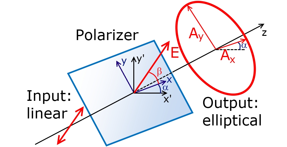
Another strategy, which is more flexible, is to split the incoming wave into two nonparallel linearly polarized eigenwaves in a birefringent material. Assume the perfect transmission of both polarizations. The waves propagating with different phase velocities in the medium gain relative phase shift . At the output port we sum them up together. In general, an arbitrary angle between linear polarizations along with arbitrary (except and ) results in an elliptical polarization Jackson (1999). From the practical point of view, however, the most convenient case is to use two orthogonal linear polarizations and with the phase shift (see Fig. 1). Then, being combined at the output, two waves
| (1) |
give an elliptical wave described by the equation
| (2) |
The principle axes of the ellipse in Eq. (2) are along the and directions.
Introducing angle between the linear incoming polarization and the axis (see Fig. 1) defines waves amplitudes and ellipticity (we assume perfect transmission for simplicity):
| (3) |
Changing angle leads to the changes in both amplitudes and ellipticity, but keeps the ellipse orientation. Rotating the polarizer and, therefore, the coordinate system connected to it, together with the incoming wave polarization with respect to the fixed coordinate system on angle (see Fig. 1) allows for changing the ellipse orientation.
In such way we can obtain any elliptical polarization starting from linear ( or ) to circular () with right or left rotation direction and with any ellipse orientation. We should note that in reality the transmission through a device cannot be 100% due to imperfections, but in order to cover the whole range of possible polarizations we just need the equality of the and polarized waves transmissions.
III Transmission line analysis
The previous section gives the general strategy for obtaining any elliptical polarization out of an incoming linear one. Now we are looking for the guidelines for the polarizer design. It is desirable for the practical applications (and also fabrication-wise) to have a thin device, so we assume that our polarization converter is a thin layer of a metamaterial with thickness .
To analyze the electromagnetic (optical) properties of the required metamaterial we employ the transmission-line (TL) approach Cronin (1995); Tretyakov (2003). In the TL theory an polarized plane wave propagating in dielectric with the refractive index is equivalent to the fundamental mode of a rectangular dielectric waveguide with the perfect electric(walls) and perfect magnetic(walls) boundaries. The relative (to the free-space impedance Ohm) wave impedance , where and are the relative magnetic permeability and electric permittivity of the material. For non-magnetic dielectrics , and . If we consider a plane interface between two non-magnetic dielectrics with refractive indices and , then the reflection and transmission coefficients of the normally incident plane wave are expressed through the wave impedances and
| (4) | |||
| (5) |
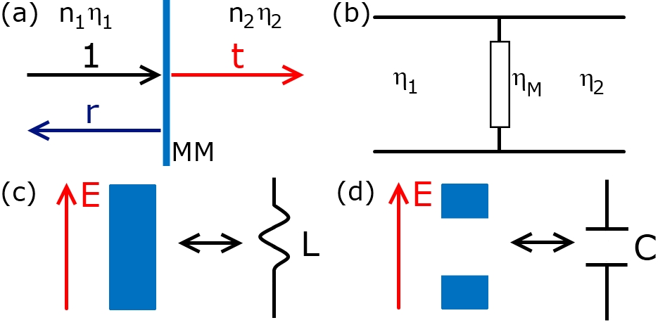
If we add a thin (much thinner than the wavelength) layer of a metamaterial with electrical impedance at the interface between two dielectrics it will act as a shunt (Fig. 2a). The equivalent normalized impedance of the shunt is (Fig. 2b), where are the periods of the unit cell of the metamaterial. The transmission , reflection , transmittance and reflectance of the wave normally incident from the left side are
| (6) | |||
| (7) | |||
| (8) | |||
| (9) |
In the extreme case of (no metamaterial layer) expressions reduce to Fresnel’s formulas (4),(5). If (short circuit, which is equivalent to a perfectly conducting mirror), we get .
To design a metamaterial-based circular polarizer we target the equal transmittances/reflectances for and polarizations and phase difference . First, we formulate the requirements on the metamaterial impedance accordingly to formulas (6)-(9). Then we analyze transmittance and reflectance (depending on configuration) from the point of view of maximal values which can be obtained by adjusting impedances. Then we guess the geometry to get the designated . The simple rules bridging the transmission line theory and optics are that the inductive impedance requires the employment of a metallic wire along the electric field (Fig. 2c), while the capacitive impedance means a dielectric gap between metallic parts (Fig. 2d). Finally, the fine tuning of the design geometry is done with the help of numerical optimization in CST Microwave Studio CST .
We begin our theoretical analysis assuming that the metamaterial is made of a perforated perfect conductor film that is a fairly good approximation for metals in the microwave and THz range. Thus, the metamaterial impedance is fully reactive (pure imaginary) , where is an effective reactance. Since we use the optical notation for the time exponential , positive means predominantly inductive impedance (), while negative means predominantly capacitive impedance . Then the transmission and reflection coefficients (6-9) are
| (10) | |||
| (11) | |||
| (12) | |||
| (13) |
where and .
The phases of reflected and transmitted waves are defined through the tangent functions:
| (14) | |||
| (15) |
III.1 Metamaterial layer: transmission configuration
Consider a single metamaterial layer in the transmission configuration Chin et al. (2008); Strikwerda et al. (2009); Roberts and Lin (2012). From the requirement of equal transmittance we find that the reactance for the and polarizations should be equal in absolute values . Among the real solutions the solution leads to the same phase advance for both polarization, and, therefore, must be excluded. So, the only suitable solution is . That means in the simplest case that the impedance of the metamaterial should be inductive for one polarization and capacitive for another.
Consequently, the transmission phase tangents . Since the phase difference should be , the product of their tangents is . Therefore, and
| (16) |
Let us, for certainty, select the positive solution for polarization then the negative solution will correspond to polarization, thus reactances are
| (17) |
The transmittance is
| (18) |
The maximal value of transmittance can be reached for (Fig. 3a), that means the metamaterial is placed between the same surrounding materials. Physically this means either a metallic membrane suspended in air Malureanu et al. (2010) or a metamaterial coated with dielectric with the same refractive index as of the substrate.
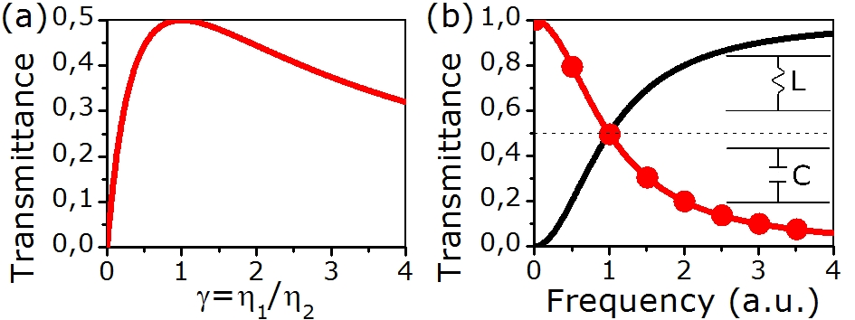
A metamaterial satisfying this solution should exhibit inductive properties for polarization (metallic wires along the axis) and capacitive for polarization (dielectric gapes orthogonally to the axis). In the transmission line analogy this is a high-frequency filter for the and low-frequency filter for the polarization (Fig. 3b). In the simplest case such polarization converter can consist of a set of metallic stripes or wires along the axis.
III.2 Metamaterial layer: reflection configuration
Now we consider a single metamaterial layer in the reflection regime Pors et al. (2011). Similarly to the transmission case reflectance for both linearly-polarized waves should be the same . So, the reactances should be identical in absolute values . Analogously to the transmission regime analysis we come to conclusion that , and then reactance can be extracted from the expression for the reflection phase (15)
| (19) |
which is a quadratic equation for . Selecting the positive sign for the polarization in equation (19), we obtain
| (20) |
The analysis of this quadratic equation reveals that there are no solutions for , so it is not possible to reach the phase difference between polarizations with any metamaterial. For the solutions for reactances for both polarizations are
| (21) | |||
| (22) |
The corresponding reflectances
| (23) | |||
| (24) |
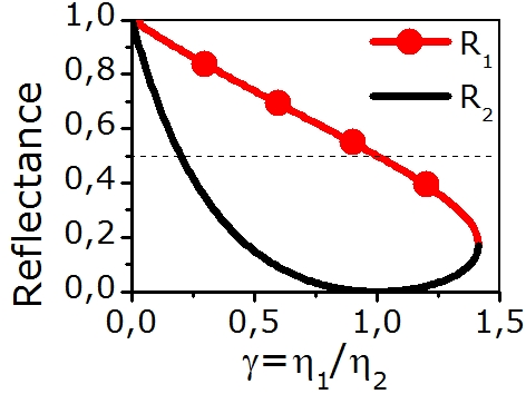
are shown in Fig. 4. For both solutions reflectance is less than 0.5 for . For the first solution (21) coincides with the maximal transmission solution (17). In this case the converter works simultaneously in reflection and transmission regimes, giving 50% reflectance and 50% transmittance.
Note, however, that the ratio can be less than 1. It can happen if the second dielectric has smaller refractive index than the first one, so the incidence should occur, for example, through a high-dielectric substrate. With such impedances reflectance can be larger than 0.5, and even equal to 1 for . It is, however, not possible to use such high-dielectric substrates due to natural limitations on the material properties and also due to a poor wave in-coupling to a high-dielectric substrate from air. For a practically important case of a silicon substrate in air, that corresponds to the reflectance and . So, in contrary to the transmission regime with the maximal polarization conversion up to 50%, it is possible to achieve larger power conversions in the reflection configuration.
III.3 Two metamaterial layers: 100% conversion efficiency in transmission
The theoretical limit for the conversion efficiency for a single layer metamaterial is 50%. We can, however, expect larger efficiency applying two layers of metamaterial separated with a dielectric spacer Kwon et al. (2008); Strikwerda et al. (2009); Weis et al. (2009); Li et al. (2010). Even very reflective mirrors arranged as a Fabry-Perot resonator can give transmittance close to 1. Let us consider a symmetric configuration shown in Fig. 5, namely, two thin identical metamaterial layers separated with a dielectric and having a dielectric from the left and from the right.
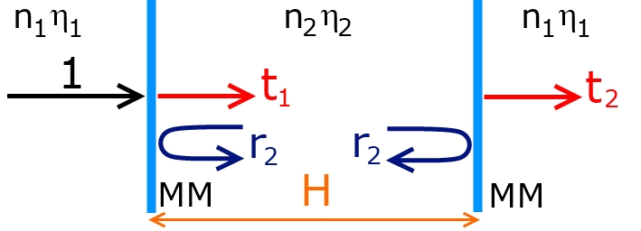
The transmission through a Fabry-Perot resonator is Yeh (1988)
| (25) |
where , is the thickness of the dielectric spacer between metamaterial layers, is its refractive index, is the free-space wavenumber and the meaning of the reflection and transmission coefficients is clear from Fig. 5.
| (26) | |||
| (27) | |||
| (28) |
Through a tedious analysis we found that equal transmittances for the and polarizations occur for the same condition for the metamaterial impedance as for a single layer.
The tangent of the transmission phase is
| (29) |
The condition for the phase difference leads to a quadratic equation for . It has two solutions
| (30) | |||
| (31) |
with the corresponding transmittances
| (32) | |||
| (33) |
where .
The transmittance for the second solution (Fig. 6) is always . However, choosing the first solution it is possible to achieve the full transmission: for . That imposes the condition for the spacer thickness
| (34) |
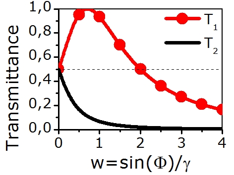
In the case when , there are no real solutions for Eq. (34), and it is not possible to achieve even theoretically the 100% transmittance. Such situation can happen if the metamaterials layers are separated with a high refractive index dielectric. Nevertheless, by coating the metal layers with additional dielectric (see, for example the meanderline structure in Strikwerda et al. (2009)) it is always possible to reduce the ratio and improve the transmission characteristics.
III.4 Metamaterial layer above ground plane: 100% conversion efficiency in reflection
Despite a larger conversion efficiency in the reflection configuration comparing to the transmission regime, the reflectance is not 100% (see Subsection B). Moreover, the incidence from the high-dielectric material side requires preliminary in-coupling to a substrate and therefore some power backscattering. It is, however, possible to overcome these challenges and reach up to 100% reflectance for the incidence from air by using a metal mirror (ground plane) below the metamaterial layer (Fig.7) Hao et al. (2007, 2009); Strikwerda et al. (2011); Wang et al. (2012).
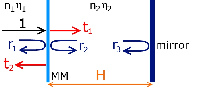
Physically such system is a kind of the Fabry-Perot resonator with a perfect mirror () and a metamaterial mirror (see Fig. 7). The total reflectance from this system is Yeh (1988):
| (35) |
where and the meaning of the reflection and transmission coefficients is clear from Fig. 7
| (36) | |||
| (37) | |||
| (38) | |||
| (39) |
For the case of the perfect ground plane the reflectance is unitary for both polarizations at any frequency. The wave has simply no other options than to be reflected. A tedious analysis of the reflection phase shows that
| (40) |
Requirement ensures the phase difference between polarizations. That leads to a parametric quadratic equation
| (41) |
where . This quadratic equation reduces to two independent cases of linear equations
| (42) | |||
| (43) |
So, for each specific there are two solutions that give the required converter functionality
| (44) | |||
| (45) |
It means that for any specific thickness for any given polarization reactance there exists a real-valued polarization reactance . Moreover, in contrary to all previous cases (transmission and reflection from a single metamaterial layer or transmission through a double layer), the reactances and are not obliged to be of different signs. They can be both positive or negative. It is possible to use a fully inductive (or capacitive) metamaterial for both polarizations, for example, a two-dimensional wire grid (or patches).
We note that, in principle, we have 4 variables that we can change in design: metamaterial impedances and , dielectric impedances ratio and the thickness of the second dielectric H. The simplest tuning can be done by the dielectric thickness optimization. An important question is whether there can be always found the value of for any given pair of .
| (46) | |||
| (47) |
which have solutions
| (48) | |||
| (49) |
when conditions
| (50) | |||
| (51) |
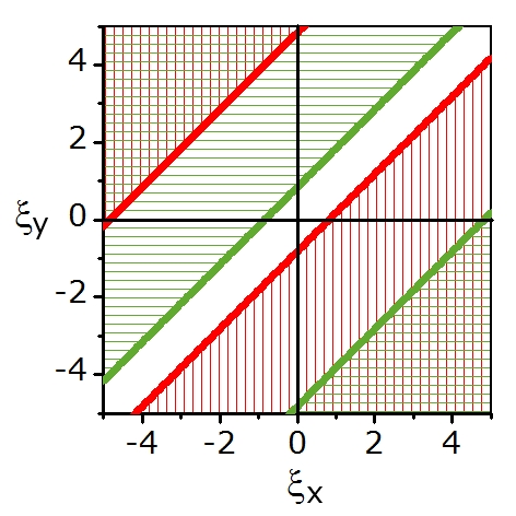
are satisfied. The graphical representation of allowed is shown in Fig. 8. There are values of corresponding to two or only one solution for and therefore for . There are also ranges, where apparently no solutions exist. This result is expected since for the case of equal impedances no phase difference between polarizations can occur upon reflection.
IV Simulation results
In order to test the abovementioned theoretical findings we developed several polarization converters based on the same unit cell geometry, aiming the THz frequency range around 1 THz. The simulations were done in CST Microwave Studio CST . We applied the periodic (unit cell) boundary conditions in the and directions, and open space boundary conditions (perfectly matched layers) in the direction. We used silver described with the Drude model (rad/s, Hz)) as metal and silica () in most cases as dielectric. Only in the single layer reflection configuration we used silicon ().
As we mentioned before, the simplest shape for the simultaneously polarization capacitive and polarization inductive metamaterial is a stripe grid with dielectric gaps in the direction. To obtain more flexibility in the geometrical parameters we modified the stripes to the unit cell shown in Fig. 9. The geometrical sizes of the characteristic features, optimized for the highest possible transmission or reflection in all four regimes are presented in Table 1. We use the following designations: T1 - single metamaterial layer polarization converter in transmission; R1 - single metamaterial layer polarization converter in reflection; T2 - double metamaterial layer polarization converter in transmission and R2 - single metamaterial layer polarization converter with a ground plane.
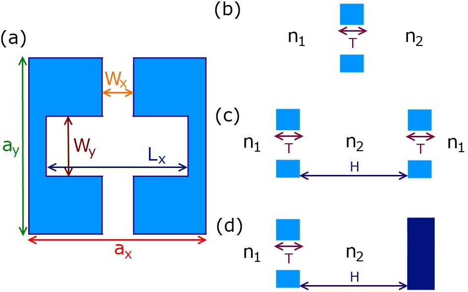
| Parameter | T1 | R1 | T2 | R2 |
|---|---|---|---|---|
| (m) | 75 | 60 | 105 | 30 |
| (m) | 75 | 50 | 65 | 30 |
| (m) | 72 | 55 | 103 | 18 |
| (m) | 19 | 10 | 50 | 7.5 |
| (m) | 30 | 17 | 40 | 8 |
| (m) | 1 | 1 | 1 | 1 |
| (m) | - | - | 30 | 55 |
The numerical results for the transmittance/reflectance and phase difference between polarizations for different designs (T1, R1, T2 and R2) are shown in Fig. 10. For all designs we demonstrate the polarization conversion close to the theoretical maximum and the phase difference close to . The double layer structure (T2) has the transmittance (Fig. 10c) almost twice as large as for the single layer (T1) (Fig. 10a). The mirror-based design R2 is, as expected, polarization insensitive and achromatic in the whole frequency range (Fig. 10d).
We should mention that both the transmittance/reflectance values and the phase difference influence the conversion efficiency. To account for both influences and to determine the working bandwidth we used the approach established by Rahm et al. Weis et al. (2009). The figure-of-merit () for the converter, also known as flattening, shows how close the polarization ellipse is to a circle for the input linear polarization incident at . To calculate it one should get a normalized electric field vector at the output , where and are unit vectors in the corresponding directions. Then, to calculate the angle and vectors corresponding to ellipse’s semi-axes and . Eventually, . Plus or minus should be chosen depending on whether or is the major semi-axis. The figure-of-merit close to 0 shows that the polarizer works well. The working range is defined as the frequency range, where Weis et al. (2009). The steepest phase difference profile is observed for the R1 design, what is reflected in the narrowest bandwidth (Fig. 10(e)). The broadest FoM is observed with the T2 design due to the flatness of the phase difference spectral profile. The main parameters of the polarizers: theoretical conversion efficiency (), conversion efficiency extracted from simulations (), bandwidth () and relative bandwidth (THz) are presented in Table 2.

| Design | at 1 THz | (GHz) | ||
|---|---|---|---|---|
| T1 | 50% | 50% | 129 | 0.129 |
| R1 | 84% | 81% | 57 | 0.057 |
| T2 | 100% | 94% | 273 | 0.273 |
| R2 | 100% | 99.7% | 134 | 0.134 |
V Discussion and conclusions
We have performed the general analysis of a metamaterial based polarization converter capable to transform a linearly-polarized incident wave into elliptically-polarized with any desired ellipticity and ellipse orientation. It is applicable to any thin-film (thickness wavelength) polarization converter with linear eigenpolarizations. We claim that a polarization converter should not necessarily be based on resonant particles (the resonance usually means an increased absorption), i.e. detuned dipoles, resonant apertures, etc., but rather on special relations between impedances for eigenpolarizations. Such impedances can correspond to the resonant or non-resonant metamaterials. The latter case usually provides a broader operation bandwidth. Even though it is not possible to remove completely parasitic capacitance and inductance, so resonances always exist. However, by a proper design we can tune the metamaterial to the frequency far away from an undesirable resonance.
As soon as the clear identification of the impedances and geometrical parameters of elements exist it is not a problem to rescale the metamaterial polarization converter to virtually any range of electromagnetic waves. In particular, we have successfully checked the scaling of the T1 design up to the telecom frequencies.
We have also showed numerically that a single type of the metamaterial unit cell can be used for any converter configuration: all four our designs T1, R1, T2, R2 are based on the same type of a unit cell differing only by optimized values of characteristic features. The one-layer transmission configuration T1 has been proved to have theoretical limit of conversion efficiency 50%. Previously 50% Chin et al. (2008), 45% Strikwerda et al. (2009) and 44% Roberts and Lin (2012) were reported. The maximal reflectance approaches 80-90% for a single metamaterial layer with realistic dielectric properties (silicon substrate), however the steep spectral dependence of the phase shifts reduces the working range of the polarizer. Resonant antennas system was reported to provide 40% in reflectance Pors et al. (2011). We have demonstrated that a linear-to-circular polarization converter exhibits better performance (with the upper limit 100% transmittance or reflectance) when two metamaterial layers are involved. The broadest working range 273 GHz is found for the transmission double layer configuration T2. The reported results for the transmittance for such systems (74% Weis et al. (2009), 25% Li et al. (2010), 80% Strikwerda et al. (2009) and 50% Kwon et al. (2008)) can theoretically be improved. The case of the metamaterial above a ground plane can also be classified as double-layer system, since due to the presence of the mirror plate the wave passes twice through the metamaterial layer. Almost 100% conversion efficiency was reported: 96% Wang et al. (2012), Strikwerda et al. (2011) and Hao et al. (2007). The important advantage of the reflection design with a ground plate is that the requirements for the impedances values are rather softened, which can facilitate greatly the design and fabrication of the structure. Even though the transmission configuration is conventionally preferable for the real life experiments, we should note, that the reflection polarizer configuration can be easily converted into transmission one with the help of additional mirrors (Fig. 11).
We believe that our general approach will become a useful tool for the metamaterials based polarization converters design and development.

Acknowledgments
The authors acknowledge P.U. Jepsen and A. Strikwerda for useful discussions. A.A. acknowledges financial support from the Danish Council for Technical and Production Sciences through the GraTer (11-116991) project.
References
- Jepsen et al. (2011) P. Jepsen, D. Cooke, and M. Koch, Laser & Photonics Reviews 5, 124 (2011).
- Kleine-Ostmann and Nagatsuma (2011) T. Kleine-Ostmann and T. Nagatsuma, Journal of Infrared, Millimeter, and Terahertz Waves 32, 143 (2011).
- Tonouchi (2007) M. Tonouchi, Nature Photonics 1, 97 (2007).
- Molter et al. (2012) D. Molter, G. Torosyan, G. Ballon, L. Drigo, and R. Beigang, Optics Express 20, 26163 (2012).
- Masson and Gallot (2006) J. Masson and G. Gallot, Optics Letters 31, 265 (2006).
- Arikawa et al. (2012) T. Arikawa, X. Wang, A. a. Belyanin, and J. Kono, Optics Express 20, 19484 (2012).
- Strikwerda et al. (2009) A. C. Strikwerda, K. Fan, H. Tao, D. V. Pilon, X. Zhang, and R. D. Averitt, Optics Express 17, 136 (2009).
- Saha et al. (2010) S. C. Saha, Y. Ma, J. P. Grant, A. Khalid, and D. R. S. Cumming, Optics Express 18, 12168 (2010).
- Drezet et al. (2008) A. Drezet, C. Genet, and T. Ebbesen, Physical Review Letters 101, 1 (2008).
- Chin et al. (2008) J. Y. Chin, M. Lu, and T. J. Cui, Applied Physics Letters 93, 251903 (2008).
- Chin et al. (2009) J. Y. Chin, J. N. Gollub, J. J. Mock, R. Liu, C. Harrison, D. R. Smith, and T. J. Cui, Optics Express 17, 7640 (2009).
- Peralta et al. (2009) X. G. Peralta, E. I. Smirnova, A. K. Azad, H.-T. Chen, A. J. Taylor, I. Brener, and J. F. O’Hara, Optics Express 17, 773 (2009).
- Weis et al. (2009) P. Weis, O. Paul, C. Imhof, R. Beigang, and M. Rahm, Applied Physics Letters 95, 171104 (2009).
- Li et al. (2010) T. Li, S. M. Wang, J. X. Cao, H. Liu, and S. N. Zhu, Applied Physics Letters 97, 261113 (2010).
- Roberts and Lin (2012) A. Roberts and L. Lin, Optics Letters 37, 1820 (2012).
- Sun et al. (2011) W. Sun, Q. He, J. Hao, and L. Zhou, Optics Letters 36, 927 (2011).
- Hao et al. (2007) J. Hao, Y. Yuan, L. Ran, T. Jiang, J. Kong, C. Chan, and L. Zhou, Physical Review Letters 99, 1 (2007).
- Hao et al. (2009) J. Hao, Q. Ren, Z. An, X. Huang, Z. Chen, M. Qiu, and L. Zhou, Physical Review A 80, 1 (2009).
- Pors et al. (2011) A. Pors, M. G. Nielsen, G. Della Valle, M. Willatzen, O. Albrektsen, and S. I. Bozhevolnyi, Optics Letters 36, 1626 (2011).
- Strikwerda et al. (2011) A. C. Strikwerda, R. D. Averitt, K. Fan, X. Zhang, G. D. Metcalfe, and M. Wraback, International Journal of High Speed Electronics and Systems (IJHSES) 20, 583 (2011).
- Wang et al. (2012) F. Wang, A. Chakrabarty, F. Minkowski, K. Sun, and Q.-H. Wei, Applied Physics Letters 101, 023101 (2012).
- Singh et al. (2010) R. Singh, E. Plum, W. Zhang, and N. I. Zheludev, Optics Express 18, 13425 (2010).
- Li et al. (2011) S. Li, Z. Yang, J. Wang, and M. Zhao, Journal of the Optical Society of America. A 28, 19 (2011).
- Mutlu et al. (2011) M. Mutlu, A. E. Akosman, A. E. Serebryannikov, and E. Ozbay, Optics Letters 36, 1653 (2011).
- Zhao et al. (2012) Y. Zhao, M. A. Belkin, and A. Alù, Nature Communications 3, 870 (2012).
- Sabah and Roskos (2012) C. Sabah and H. Roskos, Progres in Electromagnetics Research 124, 301 (2012).
- Gansel et al. (2012) J. K. Gansel, M. Latzel, A. Frölich, J. Kaschke, M. Thiel, and M. Wegener, Applied Physics Letters 100, 101109 (2012).
- Caloz and Itoh (2006) C. Caloz and T. Itoh, Electromagnetic metamaterials: transmission line theory and microwave applications: the engineering approach (Wiley-IEEE Press, 2006).
- Jackson (1999) J. Jackson, Classical electrodynamics, Vol. 67 (John Wiley & Sons, New York, 1999) p. 841.
- Cronin (1995) N. J. Cronin, Microwave and optical waveguides (Taylor & Francis, 1995).
- Tretyakov (2003) S. Tretyakov, Analytical modeling in applied electromagnetics (Artech House Publishers, 2003).
- (32) CST, “Computer simulation technology, as,” .
- Malureanu et al. (2010) R. Malureanu, P. U. Jepsen, X. S., Z. L., C. D. G., A. A., and L. A. V., Proceedings SPIE 7711, 77110M (2010).
- Kwon et al. (2008) D.-H. Kwon, P. L. Werner, and D. H. Werner, Optics Express 16, 11802 (2008).
- Yeh (1988) P. Yeh, Optical waves in layered media, Vol. 95 (Wiley Online Library, 1988).