Response of CdWO4 crystal scintillator for few MeV ions and low energy electrons
Abstract
The response of a CdWO4 crystal scintillator to protons, particles, Li, C, O and Ti ions with energies in the range 1 – 10 MeV was measured. The non-proportionality of CdWO4 for low energy electrons (4 – 110 keV) was studied with the Compton Coincidence Technique. The energy dependence of the quenching factors for ions and the relative light yield for low energy electrons was calculated using a semi-empirical approach. Pulse-shape discrimination ability between quanta, protons, particles and ions was investigated.
keywords:
Scintillation detectors , CdWO4 crystal , Quenching , Non-proportionality in scintillation response , Scintillation pulse-shape , Dark matter detectionPACS:
23.40.-s1 Introduction
Numerous astronomical and cosmological observations since 1930’s suggest that most of the matter in the Universe is non-luminous and non-baryonic, while usual matter constitutes only of the Universe and the main components are dark matter () and dark energy () [1, 2]. Dark matter (DM) is preferably related with particles which are neutral and only weakly interacting with matter (Weakly Interacting Massive Particles, WIMPs). Interaction of such particles with usual matter could be detected through observation of nuclear recoils created after scattering of WIMPs on atomic nuclei in sensitive detectors placed in low background conditions deep underground. Positive evidence of WIMPs observation at confidence level is reported in the DAMA experiment [3] after 13 years measurements with large mass low background NaI(Tl) scintillators. This result was recently supported by the CoGeNT [4] and CRESST [5] data. However, many other searches for WIMPs to-date gave only negative results [6, 7]. Because of the fundamental importance of the question of the DM constituents, searches for WIMPs are under performance or planned in near twenty experiments, in particular, in the ton-scale projects EURECA with cryogenic Ge and different crystal scintillating bolometers [8], DARWIN with scintillating noble gases [9] and DAMA/1ton (proposed since 1996) [10].
When the energy released by the recoil ions is measured with scintillators, one of the main questions is the quenching of the scintillation light yield. Since a long time it is known that the amount of light produced in scintillating materials by highly ionizing particles is lower than that produced by electrons of the same energy [11]. In a scintillator calibrated with sources, signals from ions will be seen at lower energies than their real values, sometimes by more than one order of magnitude. Knowledge of quenching factor, QF (i.e. ratio of the measured ion energy in scale to its real energy) is very important in searches for WIMPs and in predictions where the WIMPs signal should be expected. QFs depend on many factors such as: the scintillating material itself, its dopants and impurities, temperature; ion’s and numbers, ion’s energy; time of collection of scintillating signal, etc. (see some examples in [12]). Since it is sometimes quite difficult to measure QFs for the needed ions and in the needed energy region (f.e. for low-energy heavy ions when the scintillation signal is expected at keV or less), some methods for the QFs estimation are of great interest.
QFs for different ions in a scintillator could be not independent but related quantities. Such a hypothesis, supported by some experimental data, was discussed already in [11]. If true, on the basis of measurements of QFs for particles of one kind in some energy region (e.g. for a few MeV particles from internal contamination of a detector), one would be able to calculate QFs for particles of another kind and for other energies (e.g. for low energy nuclear recoils). Further evidences in favor of this hypothesis were given in [12].
Cadmium tungstate (CdWO4) crystal scintillators are widely used in low counting experiments to search for decay [13, 14, 15, 16, 17] and studies of rare [18, 19] and [20] decays. CdWO4 has rather similar properties to CaWO4, ZnWO4, CaMoO4 and some other oxide crystal scintillators, promising targets for DM experiments [8].
In this work we measured the response of a CdWO4 crystal to few MeV energy ions and low energy ( keV) electrons. Pulse-shape discrimination ability was studied for protons, particles, Li, C, O and Ti ions. Using the measured quenching for protons, we applied a semi-empirical approach [12] to calculate QFs for other ions and low energy electrons.
2 Crystal characteristics and signal processing
The CdWO4 crystal studied in this work is a parallelepiped of mm, manufactured by Scionix. CdWO4 is a monoclinic, almost orthorhombic, crystal. From the specification of the manufacturer, the mm faces are known to be cleavage (010) planes. Measurements performed with a diffractometer111These measurements have been performed at the “Centro di Cristallografia Strutturale” of the University of Firenze. confirm this assignment, while the two faces mm and mm almost correspond to planes of indexes (100) and (001), respectively.
The crystal is optically coupled through a mm face to a photomultiplier (PMT) ETL mod. 9256B. Its photocathode has an extended green response for a better matching with the light emission spectrum of the CdWO4 crystal. In the measurements with low energy electrons the crystal has been wrapped with Teflon tape, while in measurements under beam an aperture of mm has been opened in the tape covering one mm face, so that ions can enter directly. It has been verified with sources that no measurable difference in light collection is found with or without aperture. The energy scale of the detector was established with 22Na, 57Co, 60Co, 137Cs and 241Am calibration sources.
In all the measurements the anode signals from the PMT are processed by a current to voltage converter which acts also as antialiasing filter and analysed by a transient digitiser222The main characteristics are: 12 bits (11-effective), 20 Ms/s, mV linear range. already described in [21]. The data, sequentially digitised every 50 ns, are stored in a temporary memory FIFO, which, in the presence of an event trigger, is stopped and read in a time interval starting about 30 s before the time of the event and extending to 128 s on the whole. These data are stored on a mass memory for further analysis. In particular the amplitude spectra are obtained by the following procedure: for each event the mean value of the baseline is evaluated in the first 25 s and subtracted channel by channel, afterwards the signal amplitude is obtained by summing up the channel contents in a time interval lasting 55 s from the beginning of the signal. It is also checked whether the analysed waveform is in true or chance coincidence with the event trigger; overlapping waveforms are recognised and discarded.
3 Response to protons, particles, Li, C, O and Ti ions
3.1 Measurements with pulsed beams
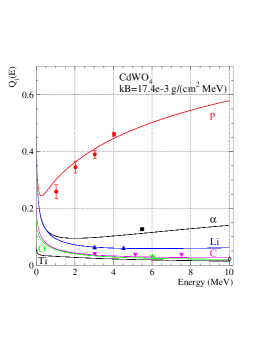
Beams of protons, Li, C, O, and Ti ions, in the energy range MeV, were produced by the Tandetron accelerator of LABEC at the INFN-Florence. A dedicated beam line [22] provides short pulses by means of an electrostatic deflector which displaces the beam spot across a narrow window obtained by an adjustable slits system, housed at the entrance of the vacuum chamber, situated at the end of the beam-line and containing the crystal. The beam intensity and the width of the slits were adjusted to obtain the arrival of a single particle per pulse in a large majority of the cases. As already said in Section 2, in all these measurements the accelerated particles enter the crystal perpendicularly to a 20 mm x 25 mm (001) face. In these measurements the event trigger was derived from the voltage transition of the deflecting plates. Owing to this coincidence constraint on the stored pulse shapes, it is possible to build from them energy spectra almost free from background. The measured quenching factors for protons (1.0, 2.0, 3.0, 4.0 MeV), Li (3.0, 4.5 MeV), C (3.0, 5.1, 7.5 MeV), O (6.0 MeV) and Ti (10.0 MeV) ions are presented in Fig. 1.

Differences of the pulse shapes, as a consequence of different specific energy losses, have been also investigated.
3.2 Measurements with particles
In addition to measurements with accelerated ions, the CdWO4 crystal was irradiated with particles. A collimated 241Am source was placed, inside the crystal chamber, in front of the crystal (001) face and, at the same time, the crystal was irradiated by 137Cs and 60Co sources in order to get a reference energy scale. In this case a self-trigger was used and, taking advantage from the different zero-crossing times, particle and ray spectra were easily disentangled. From this measurement the quenching factor for the 5486 keV particles, entering perpendicularly the (001) face, was found to be 0.127(1) as reported in Fig. 1. In a different series of measurements, the three faces of the bare crystal have been irradiated with particles. The measured QFs were: 0.197(1) for (010) face, 0.167(1) for (100) face and 0.134(1) for (001) face. These measurements can be helpful for determining the response of the crystal to particles created in its volume and moving in random directions with respect to the principal planes. A comment is required by the small () but significant difference between the two QF values relative to the (001) face: most probably, the difference could be attributed to the different light losses associated to the different locations of and light emitting sources (a surface point-like light source in the case of particles and a volume distributed light source in the case of rays) with respect to the different reflecting and diffusing properties of the bare and Teflon wrapped crystal.
Difference in QFs for particles moving in different directions, in addition to CdWO4 detectors (here and e.g. in [20]) was observed also for ZnWO4 [23] and MgWO4 [24] crystal scintillators. As quenching depends on ionization density [11], such a behavior of the QFs has to be related with difference in ionization density and stopping power for particles moving in different directions inside an anisotropic crystal. This interpretation is also supported by the behavior of the shape indicator (Section 3.4), which also depends on the direction of the particles, being closer to that of s when the quenching factor is larger. Differences of light collection due to surface effects could, in fact, change the quenching factor but hardly modify the shape of the light pulse.
3.3 Calculations of quenching factors for ions
Quenching factors for protons, particles and Li, C, O, Ti ions in the CdWO4 scintillator were calculated following the work [12], which is based on the classical Birks formula [11], as the ratio of light yield of an ion to that of an electron of the same energy:
| (1) |
where
| (2) |
| (3) |
Here and are the total stopping powers for ions calculated with the SRIM code [25] and electrons calculated with the ESTAR code [26], respectively.
Supposing the normalization factors equal for electrons and ions and independent on energy, we obtain that depends only on a single parameter (the Birks factor). It is assumed that is also independent of energy and has the same value for all ions, if all data are measured under the same experimental conditions and treated in the same way [12].
To determine the value for the present CdWO4 measurements, the experimental points for protons were fitted by curve calculated with Eq. (1)–(3). The result is mg cm-2 MeV-1, and the obtained curve is shown in Fig. 1. Afterwards, QFs for all other ions were calculated with this value; all the results are also demonstrated in Fig. 1.
As one can see, the calculations do not perfectly reproduce the experimental points, with the biggest deviation () for Ti ions. Nevertheless, general agreement could be considered as acceptable, especially for a theory with only one parameter. Sometimes quenching factors in DM experiments are known with much bigger uncertainties, and calculations in accordance with the above described approach could give valuable information on the expected QF values.
3.4 Pulse-shape discrimination between quanta, protons, particles and light ions
To test the ability of pulse-shape discrimination between quanta ( particles), protons, particles and the light ions, the data were analyzed by using the optimal filter method proposed by E. Gatti and F. De Martini [27] (see also [28] where the analysis was developed for CdWO4 crystal scintillators). For each experimental signal, its shape indicator was defined as , where the sum is over time channels , starting from the origin of signal and up to 60 s, is the digitized amplitude of a given signal. The weight function is defined as: , where the reference pulse shapes and are the average of a few thousands shapes for particles and quanta, respectively, collected in the measurements with and sources.
Distributions of the shape indicator versus energy for quanta, protons, particles, Li, C, O and Ti ions measured with CdWO4 crystal scintillator are presented in Fig. 2. There is clear discrimination between s, protons, particles and ions. The shape indicator values for protons and ions lie near the ones of particles. This fact, however, does not necessarily imply that the pulse shape be equal for heavier ions and protons.

It is worth to note also that the measurements with 241Am particles entering into different faces of the CdWO4 crystal (Section 3.2) show a clear relation between quenching factor and shape indicator: for bigger , when signal is closer to signal caused by quanta, value is lower, i.e. also closer to . This effect was already observed in [20, 23].
4 Measurements with low energy electrons
It should be noted that the quenching of scintillation signals is observed not only for ions but also for low-energy (less than a few hundred keV) quanta and electrons. However, the nature of the electron-induced light-emitting excitation can have a different origin from that induced by heavy ions. Possible relation between QFs for ions and QFs for electrons is interesting and important as giving an additional method to obtain QFs for recoils induced by WIMPs in scintillators.
A lot of work has been dedicated, also recently, to the study of the non-linearity of the response of scintillating crystals, coupled to different types of photo-detectors (photomultipliers in many cases), to low-energy quanta and electrons (see e.g. [29, 30, 31, 32, 33, 34, 35, 36] and works quoted therein). We have studied the response of a CdWO4 scintillation detector to low energy electrons by using electrons created in the CdWO4 crystal by Compton scattered quanta.
4.1 Experimental set-up
To avoid surface effects for low energy electrons, the CdWO4 crystal under study is used as a Compton spectrometer333This method was first proposed by Valentine and Rooney [37, 38].. This technique requires that the rays, scattered by the crystal at an angle with respect to the direction of the incoming collimated monochromatic beam, be detected in coincidence with the signals generated in the crystal by the corresponding scattered electrons. However, when the energy of the scattered electrons is small, typically less than 20 keV, it becomes difficult to achieve reliable information both in energy and in timing, particularly for crystals, such as CdWO4, whose main light emission is characterised by a long decay time (s) [39]: in that case a small anode signal consists of a sequence of almost randomly spaced single electron responses.
To overcome this problem, we have used the production in opposite directions of the two 511 keV rays from the singlet positronium following the decay of 22Na. This variant of the Compton Coincidence Technique makes it possible to obtain a good timing of the event trigger through the coincidence between one of the rays observed by a NaI(Tl) counter and the other one observed in a high purity germanium (HPGe) counter, after been scattered in the crystal under study, and therefore to study the response to electrons down to very low energy also for CdWO4. Moreover the collimation of the rays, impinging on the crystal, is performed via coincidences with NaI(Tl), so avoiding the border effects of a physical collimator. The front-end electronics for the NaI(Tl) detector consists of a passive integrator of the anode current signals followed by a JFET input linear buffer feeding a semi-gaussian shaping amplifier (Ortec mod. 572: time constant 0.5 s) whose bipolar output is sent to a Timing Single-Channel Analyzer (Ortec, mod. 551). HPGe signals, from one of the twin outputs of the charge preamplifier, are processed in the same way as those of the NaI(Tl) detector and provide timing information, while the other preamplifier output is connected to a Gated Integrator Amplifier (Ortec: mod. 973) with integration time 5 s, and used for energy measurement.
The geometry of the experimental set-up is shown in Fig. 3. The 22Na source has nominal activity 400 kBq. 22Na decays to the 1274.5 keV, first excited level of 22Ne, through a ( = 546 keV) annihilating in a 2 mm diameter zone.
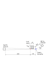
As shown in Fig. 3, the source is on the axis of a system of two detectors: a NaI(Tl) (manufactured by Scionix) and the CdWO4 crystal described in Section 2. The 10 mm thickness of this crystal causes an attenuation of the 511 keV rays of 60%. Special care has been devoted to minimise the material surrounding the CdWO4 crystal and thus the probability of absorption and scattering along the path of the 511 keV rays: to this purpose the cap surrounding the CdWO4 is a cylinder of aluminium of only 0.4 mm thickness. The 800 mm distance between source and front face of the NaI(Tl) detector defines a solid angle of maximum angular aperture of 5.4∘, so that a 511 keV ray impinging on this detector has a companion 511 keV ray hitting the CdWO4 crystal inside a circle of 16 mm diameter.
The 511 keV rays scattered at angle from the crystal are detected by an HPGe detector (Ortec: mod. GMX 30 P: diameter 60 mm, height 60 mm, relative efficiency 30% and resolution (FWHM) 1.9 keV at 1.33 MeV). The HPGe detector is placed at mm from the centre of the crystal and, in successive measurements, at angles of (12.5, 20.0, 35.0)∘ with respect to the axis defined by the NaI(Tl) detector and the CdWO4 crystal. In this way, the overall angular range covered by the HPGe extends, with variable efficiency, from to , corresponding to energies of the scattered rays from 510 keV to 395 keV and a complementary energy range of Compton electrons inside the CdWO4 from 1 keV to 116 keV.
It is worth to stress that with this set-up the problem of the time mark associated to even very low energy events in the crystal is overcome, because the event trigger is obtained from the coincidence of 511 keV full-energy signals detected by the NaI(Tl) and signals detected by the HPGe in the energy range (390 – 511) keV. A drawback of this method concerns the intrinsic energy spread of the 511 keV rays, which brings the FWHM of the 511 keV line to keV (the intrinsic HPGe resolution at this energy is keV).
For monitoring gain and baseline of the HPGe, a 133Ba source is placed near the HPGe detector and shielded by a 25 mm lead shield from the CdWO4 crystal. For the same purpose, a source of 241Am (emitting 60 keV photons) is placed near the CdWO4. Lead shields have been also introduced which, to some extent, prevent 511 keV (and to a lesser extent 1274.5 keV) rays from the 22Na source, from directly reaching the HPGe detector.
At the arrival of an event trigger, the linear signal from HPGe is peak analysed (by a 100 MHz, 8k ADC) and recorded, together with the information on CdWO4 “signal shape”, on a dedicated PC. As an example, the relevant part (470 keV – 520 keV) of the HPGe spectrum corresponding to rays scattered from the CdWO4 crystal in a 4-days run (corresponding to about one tenth of the total statistics) at a mean angle , is shown in Fig. 4. The broad structure (”bump”) in the spectrum is due to 511 keV s Compton scattered in the crystal, which are in prompt coincidence with the event trigger. The out-of-coincidence spectrum (Fig. 4) clearly shows a 511 keV full energy peak, which is followed (because of multiple scattering) by a small tail extending from the full-energy peak down to the Compton edge. Obviously, a distribution of the same relative size is present at the low energy side of each channel of the bump and the combined effect of all channels produces the low-energy tail extending well below the minimum energy of the scattered s. This effect certainly contributes, with increasing importance, to the lower-energy part of the bump. Owing to this reason, only the upper part of the bump has been considered in the analysis.
In Fig. 4, the corresponding digitizer pulse amplitude spectrum of electrons in prompt coincidence is reported. The nominal energy scale (“apparent electron energy” ) is normalised to the full-energy peak of 511 keV, corresponding to a full absorption of the inside the crystal. Due to the non-linear response, the energy scale does not reproduce the true energy of low-energy electrons.
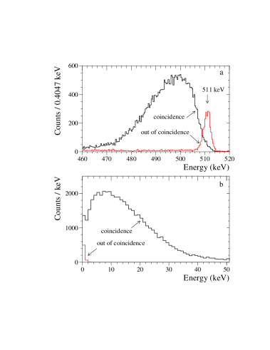
The small rise of the electron spectrum at the lowest energies is completely accounted for by the background distribution (see the out-of-coincidence spectrum in Fig. 4).
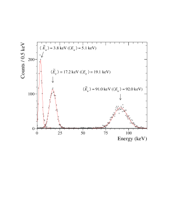
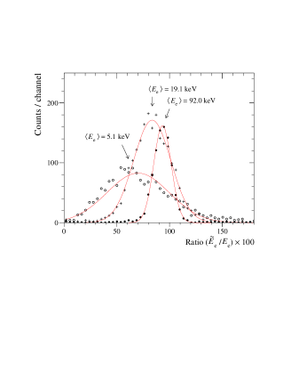
Within the statistical uncertainties, the energy of electrons associated to a ray of energy is keV – . The bump in the distribution of , shown in Fig. 4, as well as those at and , have been divided in bins 2 or 4 keV wide, and for each bin the distribution of electron signal amplitudes from CdWO4 has been obtained. Examples of the amplitude spectra of electrons are presented in Fig. 5 for mean energies 5.1 keV and 19.1 keV (from 2-keV bins), and 92 keV (4-keV bin). Also in this figure, the electron pulse amplitude has been converted in keV to give the “apparent electron energy” . For each amplitude distribution, two values of the mean energy are given in the figure: the true mean energy of the scattered electrons = 511 keV – , coming from the mean value of the energy of the selected bin on the bump, and the mean of the apparent electron energy .
Distributions, as those shown in Fig. 5, have been used for two
purposes:
1) from each electron distribution the value of FWHM has been
extracted and compared with those obtained by irradiating the CdWO4
crystal with rays of similar energies from radioactive sources;
2) for each bin of the selected regions of the three bumps
(at , , )
the relative light yield
of the corresponding electron energy
distribution has been evaluated.
4.2 Response of CdWO4 crystal scintillator to low energy electrons
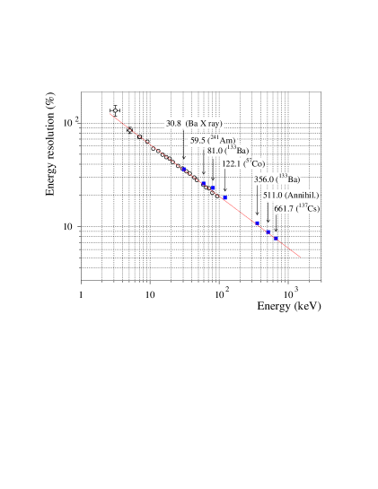
The dependence of the energy resolution on energy of electrons and s from radioactive sources in CdWO4 is reported as a function of energy in Fig. 6. The main findings are that no appreciable differences between electrons and rays are apparent in the overlapping energy region. The continuous line shows a minimum- fit of the data with the function FWHM(%); ( keV, /n.d.f. = 0.45, where n.d.f. is the number of degrees of freedom).
Concerning the relative light yield, examples of distributions of the ratios , for the same energy bins of Fig. 5, are given in Fig. 7. From this type of distributions, and for each 4-keV bin in the HPGe bumps at angles of (12.5, 20.0, 35.0)∘, the relative light yield is derived as . They are presented as a function of the true electron energy in Fig. 8. Error bars include the statistical uncertainties as well as estimated systematic errors related to the measurement itself and to the procedure of data analysis. The relative light yield remains substantially stable at the 100% value above 80 keV, decreases slowly at lower energies down to 95% at 20 keV and more deeply below this energy.
In CdWO4, no indication is found of an increase of the luminescence efficiency with decreasing electron energy, as reported for NaI(Tl). To our knowledge, no previous measurements with internal electrons have been reported for CdWO4. Compared with Fig. 10 of [30], our Fig. 8 shows a slower decrease of the for energies below 80 keV. We must remark, however, that the data of [30] are obtained by excitation with rays, and show in fact the well known anomalies at the K edge.
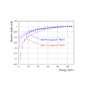
We also calculate here the relative light yield as
| (4) |
with obtained with Eq. (3) and the Birks factor mg cm-2 MeV-1, the same as was used to describe the experimental data for ions (Fig. 1); is normalised to 1 at 100 keV. However, as one can see from Fig. 8, the experimental data for electrons are better described with the value mg cm-2 MeV-1, when the points at keV are perfectly described, while disagreement still is present at lower energies. One could expect that introduction of dependent on energy (see [40, 41, 42]) or introduction of additional terms in the Birks equation (see e.g. [43]) would allow to improve the description of the data.
5 Discussion and conclusions
(1) It should be stressed, the non-proportionality in the scintillation response is an important characteristic to estimate the energy resolution achievable with scintillation crystals [30]. In accordance with current understanding (see recent reviews [33, 34, 35]), non-proportionality of the relative light yield for electrons and quanta at low energies is one of the main reasons of poor energy resolution of a scintillator for s even at higher energies because of a high probability for a quantum to interact with a detector more than once and to lose the total energy through creation of few lower energy electrons. Many scintillating materials were studied till now (see [33, 34, 35, 36, 44, 45, 46] and refs. therein), and the best energy resolution (better that 3%) was reached with scintillators which show good proportionality of the light yield down to keV (f.e. LaCl3(Ce), LaBr3(Ce), SrI2(Eu) [35]). While response of CdWO4 to low energy quanta was already studied [30, 45], results for low energy electrons (down to 5 keV) are presented here for the first time.
(2) Measurements with the accelerator for protons, Li, C, O and Ti ions with energies in 1 – 10 MeV interval, together with the 5.5 MeV particles from 241Am, allow to obtain data on quenching factors interesting for the dark matter studies. Description of these data with Eq. (1)–(3) with the same value of the Birks factor mg cm-2 MeV-1 (obtained by fitting the data for protons), while being not perfect, nevertheless shows relevant agreement, with the biggest deviation of for Ti ions. This further supports the hypothesis [12] that quenching factors for all ions are not independent and could be described with the same value, if the data are collected in the same experimental conditions and are treated in the same way. This approach allows to obtain QFs for low energy nuclear recoils on the basis f.e. of QFs values for a few MeV particles from internal contamination of a detector. Sometimes the QFs for low energy nuclear recoils are known with uncertainties much higher than 30%, and the description with Eq. (1)–(3) could provide an important estimation of the needed QFs.
(3) It is possible to describe the obtained data on the relative light yield for low energy electrons in the CdWO4 by Eq. (4) in a perfect way for keV, however still with disagreement at lower energies. Similar description on the basis of the Birks equation was obtained previously for CaWO4 in [47] and for liquid scintillators in the Double Chooz experiment in [48]. However, for CdWO4 the value mg cm-2 MeV-1 determined for such a description is different from that obtained from fit of the data for the ions: mg cm-2 MeV-1. This unfortunately closes the additional way to obtain QFs for low energy nuclear recoils relevant for the DM searches from the light yield non-proportionality for the electrons measured with the same scintillator. This conclusion is not unexpected; it is supported also by the following considerations. As it is known (see f.e. [35]), for some scintillating materials (NaI(Tl), CsI(Tl)) the relative light yield for quanta and electrons is at low energies. At the same time, Eq. (4) can describe only quenched values (as those in Fig. 8 or in [47, 48]) but not the enhanced (giving at most only with ), thus it is not suitable for NaI(Tl). One could assume that the mechanisms of quenching for ions and non-linear response to low energy electrons (s) are different. Nevertheless, description for ions by Eq. (1)–(3) is valid also for NaI(Tl); see f.e. Fig. 13 in [12] where the value obtained by fitting data for Na recoils allowed to perfectly describe QFs for I recoils.
Acknowledgments
The authors are indebted to S. Ciattini and F. Loglio for their kind collaboration in the measurements of the structural properties of the CdWO4 crystal. The work of F.A. Danevich and V.I. Tretyak was supported in part by the Space Research Program of the National Academy of Sciences of Ukraine. We would like to thank the referee for useful suggestions.
References
- [1] J.L. Feng, Annu. Rev. Astron. Astrophys. 48 (2010) 495.
- [2] G. Bertone (ed.), Particle Dark Matter. Observations, Models and Searches, Cambridge Univ. Press, 2010.
- [3] R. Bernabei et al., Eur. Phys. J. C 56 (2008) 333; 67 (2010) 39.
- [4] C. Aalseth et al., Phys. Rev. Lett. 107 (2011) 141301.
- [5] G. Angloher et al., Eur. Phys. J. C 72 (2012) 1971.
- [6] N.J.C. Spooner, J. Phys. Soc. Jpn. 76 (2007) 111016.
- [7] W. Rau, Phys. Part. Nucl. 42 (2011) 650.
- [8] H. Kraus et al., Nucl. Phys. B (Proc. Suppl.) 173 (2007) 168.
- [9] L. Baudis et al., arXiv:1201.2402 [astro-ph.IM].
- [10] F. Cappella et al., Nuovo Cim. B 122 (2007) 707.
- [11] J.B. Birks, The Theory and Practice of Scintillation Counting, Pergamon Press, Oxford, 1964.
- [12] V.I. Tretyak, Astropart. Phys. 33 (2010) 40.
- [13] F.A. Danevich et al., Z. Phys. A 355 (1996) 433.
- [14] F.A. Danevich et al., Phys. Rev. C 68 (2003) 035501.
- [15] P. Belli et al., Eur. Phys. J. A 36 (2008) 167.
- [16] A.S. Barabash et al., JINST 06 (2011) P08011.
- [17] P. Belli et al., Phys. Rev. C 85 (2012) 044610.
- [18] F.A. Danevich et al., Phys. At. Nucl. 59 (1996) 1.
- [19] P. Belli et al., Phys. Rev. C 76 (2007) 064603.
- [20] F.A. Danevich et al., Phys. Rev. C 67 (2003) 014310.
- [21] L. Bardelli et al., Nucl. Instr. Meth. A 569 (2006) 743.
- [22] N. Taccetti et al., Nucl. Instr. Meth. B 188 (2002) 255.
- [23] F.A. Danevich et al., Nucl. Instr. Meth. A 544 (2005) 553.
- [24] F.A. Danevich et al., Nucl. Instr. Meth. A 608 (2009) 107.
-
[25]
J.F. Ziegler, J.P. Biersack, M.D. Ziegler, SRIM. The Stopping
and Range of Ions in Matter, SRIM Co., 2008;
SRIM version 2008.04, http://www.srim.org. - [26] M.J. Berger, J.S. Coursey, M.A. Zucker, J. Chang, Stopping-Power and Range Tables for Electrons, Protons, and Helium Ions, version 1.2, http://physics.nist.gov/PhysRefData/Star/Text/contents.html.
- [27] E. Gatti, F. De Martini, Nuclear Electronics 2, IAEA, Vienna, 1962, p. 265.
- [28] T. Fazzini et al., Nucl. Instr. Meth. A 410 (1998) 213.
- [29] E. Sakai, IEEE Trans. Nucl. Sci. 34 (1987) 418.
- [30] P. Dorenbos, J.T.M. de Haas, C.W.E. van Eijk, IEEE Trans. Nucl. Sci. 42 (1995) 2190.
- [31] J.E. Jaffe, D.V. Jordan, A.J. Peurrung, Nucl. Instr. Meth. A 570 (2007) 72.
- [32] W.S. Choong et al., IEEE Trans. Nucl. Sci. 55 (2008) 1073.
- [33] S.A. Payne et al., IEEE Trans. Nucl. Sci. 56 (2009) 2506.
- [34] M. Moszyński, Rad. Meas. 45 (2010) 372.
- [35] S.A. Payne et al., IEEE Trans. Nucl. Sci. 58 (2011) 3392.
- [36] I.V. Khodyuk, P. Dorenbos, arXiv:1204.4350 [cond-mat.mtrl-sci].
- [37] J.D. Valentine, B.D. Rooney, Nucl. Instr. Meth. A 353 (1994) 37.
- [38] B.D. Rooney, J.D. Valentine, IEEE Trans. Nucl. Sci. 43 (1996) 1271.
- [39] L. Bardelli et al., Nucl. Instr. Meth. A 584 (2008) 129.
- [40] G. Bizarri et al., J. Appl. Phys. 105 (2009) 044507.
- [41] Q. Li et al., J . Appl. Phys. 109 (2011) 123716.
- [42] R.T. Williams et al., Phys. Status Solidi B 248 (2011) 426.
- [43] C.N. Chou, Phys. Rev. 87 (1952) 904.
- [44] M. Moszyński, Nucl. Instr. Meth. A 505 (2003) 101.
- [45] M. Moszyński, IEEE Trans. Nucl. Sci. 52 (2005) 3124.
- [46] G. Bizarri et al., J. Lum. 129 (2009) 1790.
- [47] R.F. Lang et al., arXiv:0910.4414 [nucl-ex].
- [48] C. Aberle et al., JINST 6 (2011) P11006.