Formation and Stability of Cellular Carbon Foam Structures:
An Ab Initio Study
Abstract
We use ab initio density functional calculations to study the formation and structural as well as thermal stability of cellular foam-like carbon nanostructures. These systems with a mixed / bonding character may be viewed as bundles of carbon nanotubes fused to a rigid contiguous 3D honeycomb structure that can be compressed more easily by reducing the symmetry of the honeycombs. The foam may accommodate the same type of defects as graphene, and its surface may be be stabilized by terminating caps. We postulate that the foam may form under non-equilibrium conditions near grain boundaries of a carbon-saturated metal surface.
pacs:
61.48.De, 61.46.-w, 81.05.U-, 81.07.DeThe last few decades have witnessed an unprecedented interest in carbon nanostructures, the most prominent of them being fullerenesKroto et al. (1985), nanotubesIijima (1991) and grapheneNovoselov et al. (2004). Previously postulated hybrid carbon nanofoam structuresUmemoto et al. (2001); Kuc and Seifert (2006); Zhao et al. (2011); Enyashin and Ivanovskii (2011) with a mixed / bonding character have received much less attention for lack of direct experimental observation. The growing body of information about the formation of carbon nanostructures including grapheneRodríguez-Manzo et al. (2011), nanotubesRodriguez-Manzo et al. (2007); Lin et al. (2007) and fibersHelveg et al. (2004) on transition metal surfaces with a particular morphology suggests ways that should favor the formation of particular carbon allotropes. We propose that previously unseen nanostructures including carbon foam may form under specific conditions on a metal substrate.
Inspired by previously postulated carbon foamsUmemoto et al. (2001); Kuc and Seifert (2006); Zhao et al. (2011); Enyashin and Ivanovskii (2011), we explore ways to grow such structures on a carbon saturated metal substrate. We use ab initio density functional calculations to investigate the equilibrium structure, structural and thermal stability and elastic properties of the growing system. The foam structures we study, which have a mixed / bonding character and resemble a bundle of carbon nanotubes fused to a contiguous 3D honeycomb structure, are rather stable even as slabs of finite thickness. The foam structure may be compressed more easily by reducing the symmetry of the honeycombs. It may accommodate the same type of defects as graphene at little energy cost, and its surface may be stabilized by terminating caps. We postulate that the foam could form under non-equilibrium conditions near grain boundaries of a carbon-saturated metal surface and should remain stable until K.
Our calculations of the equilibrium structure, stability, elastic properties and the formation mechanism of the carbon foam were performed using ab initio density functional theory (DFT) as implemented in the SIESTA codeArtacho et al. (2008). We used the Ceperley-Alder Ceperley and Alder (1980) exchange-correlation functional as parameterized by Perdew and ZungerPerdew and Zunger (1981), norm-conserving Troullier-Martins pseudopotentialsTroullier and Martins (1991), and a double- basis including polarization orbitals. We used periodic boundary conditions for the 3D infinite foam structure and 2D slabs of finite thickness. The 3D foam with 10 atoms per unit cell was sampled by a fine gridMonkhorst and Pack (1976) of at least -points in the Brillouin zone. We used a mesh cutoff energy of Ry to determine the self-consistent charge density, which provided us with a precision in total energy of meV/atom.
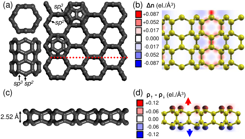
The structure of the carbon foam is depicted in Fig. 1(a). In top view, it closely resembles the graphene honeycomb lattice with two important distinctions. We find the optimum lattice constant in the honeycomb plane of the foam to be Å, which is about twice the graphene value Å. More important, 1D carbon-carbon bonds in the 2D graphene structure correspond to 2D walls in the infinite 3D foam structure. The foam cells, shown in the left panels of Fig. 1(a), closely resemble (6,0) carbon nanotubes. The foam contains 60% 3-fold coordinated C atoms, labeled , and 40% 4-fold coordinated C atoms, labeled . The gravimetric density of the optimized foam structure, g/cm3, lies in-between the experimental valuesKittel (2005) for graphite, g/cm3, and diamond, g/cm3. We find the 3D carbon foam structure to be less stable than graphene by eV/atom, which is comparable to the C60 fullerene.
In Fig. 1(b) we display the electron density difference, defined by as the difference between the total electron density and the superposition of atomic charge densities . Charge accumulation in the bond region indicates strong covalent bonding especially between neighboring atoms. Our DFT results for the electronic structure indicate that the bottom of the conduction band lies below the top of the valence band, suggesting that the infinite foam should be metallic. In reality, this finding is a well-known artifact of DFT that we correct using the LDA+U method, which indicates semiconducting behavior of the bulk structure.
Besides the bulk structure, we also considered and optimized foam slabs of different thickness. We must take into account the fact that the surface terminated with -type atoms, which are shared by two honeycombs, is inequivalent to a surface with -type atoms, which are shared by three honeycombs. The thinnest stable free-standing slab, dubbed the ‘single-decker’ structure and shown in Fig. 1(c), has both surfaces of the -type. It has some commonalities with graphitic nanostructures that show magnetic ordering at zigzag edgesOkada and Oshiyama (2003); Higuchi et al. (2004); Mañanes et al. (2008); Hod and Scuseria (2008); Kim et al. (2003). Similar to the narrowest zigzag graphene nanoribbon, our system displays a flat band near that gives rise to spin polarization with antiferromagnetic coupling across the slab, as seen in Fig. 1(d). The dominating role of the surface reduces the stability of the ‘single decker structure’ by eV/atom with respect to the bulk carbon foam. We note an even-odd alternation in the energy as a function of slab thickness in terms of the number of hexagon rows, since the slab surfaces may be either identical or different. In any case, the role of the surface decreases with increasing slab thickness, and reaches a much smaller value eV/atom in the ‘triple-decker’, shown in Fig. 1(b), than in the ‘single-decker’ structure.
The energy penalty due to unsaturated surfaces may be significantly reduced if the slab is attached to a substrate, or if the cells are covalently terminated by caps, similar to the dome termination of carbon nanotubes. We considered either a hexagon or two adjacent pentagons as candidate caps to terminate the honeycombs, as seen in the right panel of Fig. 1(a). Both caps have 6 twofold coordinated C atoms at the edge that may form covalent bonds with the surface atoms. Assuming that all honeycombs on one side are capped and using Å2 for the area of each honeycomb, we estimated the surface energy reduction associated with cap termination to be eV/Å2 for hexagonal caps and eV/Å2 for the less-stable two-pentagon caps. We need to note that this stabilization energy contains the termination energy of both the surface and the individual unsaturated caps, and that these energy terms can not easily be separated.
Since epitaxy is an issue when considering the possibility of foam growth on a metal substrate, we investigated the lateral compressibility of the foam structure. Our definition is analogous to the elastic response of a uniform isotropic 3D structure with volume to hydrostatic pressure , given by the force per area , which is represented by the bulk modulus . The elastic deformation of the area within a 2D slab structure subject to in-plane hydrostatic pressure , given by the force per length , can be represented by an analogous 2D bulk modulus, defined by . Of course, we expect to be nearly proportional to the slab thickness. We find this value to be quite useful, since it allows to determine the critical slab thickness for epitaxial growth on a particular incommensurate substrate.
Applying hydrostatic pressure in the plane of the layer, we find that the honeycomb structure may be compressed more easily by breaking the honeycomb symmetry than by uniformly compressing the honeycombs. The structure of the deformed foam, depicted in Fig. 2(a), indicates the preferential way the foam may fold. For this elastic response, we find N/m in the ‘single-decker’ and N/m in the ‘triple-decker’ structure. For the sake of comparison, when considering a very thick slab of thickness , we used the bulk calculation to obtain GPa. We find this value to be much smaller than that of the ideal structure with suppressed folding, which had been studied previouslyKuc and Seifert (2006) with results similar to our value GPa. Even though the possibility of folding reduces the bulk modulus, finite compressibility should still play a significant role during foam growth on lattice-mismatched or defective substrates.
Interestingly, we find that foam folding occurs spontaneously when the system is doped by electrons. The structure presented in Fig. 2(a) can be obtained by either applying isotropic pressure in 2D or, at zero pressure, by doping with 0.2 electrons per C atom. In the latter case, we find that folding induced by doping reduced the foam energy by eV/atom for the bulk structure.
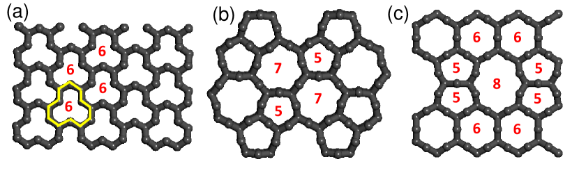
We also find that the proposed foam structure may accommodate a similar type of defects as graphene with the main difference that bond rotations in graphene correspond to wall rotations in the foam. In graphene monolayers, lines of 5775 or Stone-Thrower-WalesStone and Wales (1986); Thrower (1969) and of 558 defects have been observed to accumulate near grain boundariesHuang et al. (2011); Banhart et al. (2011); Meyer et al. (2008) and step edgesLahiri et al. (2010). Their presence reduced stress in strained free-standing layers and the lattice mismatch energy in adsorbed layers, which in this way maintained their epitaxy over large areas. The analogous 5775 or 558 defect structures in the foam are depicted in Fig. 2(b) and 2(c). Since the foam structure is rather flexible, the energy penalty associated with these types of defects is relatively small, amounting to eV/atom for the structure of Fig. 2(b) and eV/atom for the structure of Fig. 2(c) with respect to the perfect infinite honeycomb lattice. With a bulk modulus GPa, the defective and foam structures are slightly more compressible than the perfect foam with suppressed cell folding. Similar to supported graphene, these types of defects should reduce the lattice mismatch energy on a particular substrate caused by different lattice constants or, on a polycrystal, across grains with different orientation.
To find out whether the carbon foam may or may not decompose to a more stable allotrope under growth conditions, we studied its thermal stability by performing molecular dynamics (MD) simulations in the temperature range K K. To avoid artifacts caused by small unit cells, we used supercells containing 160 carbon atoms. For these large unit cells, we used the Tersoff bond-order potentialTersoff (1988) in molecular dynamics simulations covering time periods of 10 ps using 0.5 fs time steps. Our results, presented in the EPAPS on-line materialEPA , indicate that the infinite foam should be stable up to a high melting temperature near K. Even though free-standing slabs with finite thickness may be thermally less stable, termination by caps or attachment to a substrate should increase their thermal stability.
Inspired by the observed growth of grapheneRodríguez-Manzo et al. (2011) and carbon nanotubesRodriguez-Manzo et al. (2007) on cobalt saturated with carbon, we studied possible growth pathways of the foam on this substrate. To get insight into the foam-substrate interaction including optimum lattice registry, we represented the Co(0001) surface by a four-layer slab with the two bottom layers constrained in the bulk geometry. Besides the perfect Co(hcp) lattice, we also considered fcc layer stacking when discussing grain boundaries. We considered different foam terminations at the interface in order to find the optimum interface geometry. We found that the -type terminated foam surface attaches more strongly to Co(0001) than the -type terminated surface. The largest reduction of the foam surface energy by eV/Å2 occurs, when surface C atoms occupy the hollow sites. We should note that this stabilization energy reflects the reduction of both the metal and the foam surface energy.
Since a realistic representation of the growth mechanism by molecular dynamics (MD) simulations is currently not possible due to time limitations, we discuss in the following likely processes that should contribute to foam growth and judge their importance according to potential energy surfaces. To favor foam growth, we need to find a suitable substrate geometry and identify growth conditions that promote the formation of foam rather than other competing nanostructuresRodríguez-Manzo et al. (2011); Rodriguez-Manzo et al. (2007); Gao et al. (2011). Assuming that the feedstock are carbon atoms dissolved in the substrate, we consider grain boundaries and steps as preferential nucleation sites of the foam. Three competing processes contribute to the nucleation and growth of carbon nanostructures on the surface: surface diffusion of carbon, bulk diffusion of carbon inside individual grains, and bulk diffusion along grain boundaries that had not been considered previously.
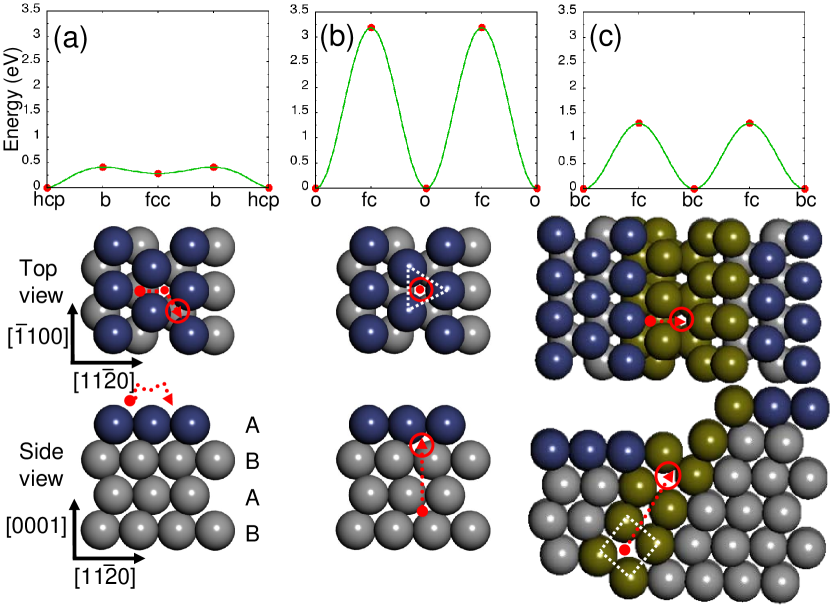
Our results for these three processes are presented in Fig. 3. Since surface diffusion of C atoms, depicted in Fig. 3(a), does not require displacement of substrate metal atoms, it occurs with a low activation barrier of only eV and should be the fastest process of all. The optimum path involves diffusion between the more stable hollow sites, with the hcp sites being energetically favored by eV over the fcc sites, across less stable bridge sites labeled b.
In bulk cobalt, carbon atoms prefer energetically the octahedral interstitial sites over the tetrahedral sites. The optimum bulk path, presented in Fig. 3(b), involves diffusion normal to the surface between octahedral (o) sites across barriers at the triangular face centers (fc) of the octahedra. We emphasized one triangular face of an octahedron by the white dotted line in the middle panel of Fig. 3(b). In this view, the barrier fc site in the center of the triangle separates the favored o sites directly below and above. Since the Co atoms are closely packed in the hcp structure, passing through the center of the triangular face requires displacing atoms, which requires a high activation energy of eV. This value is to be considered an upper limit, since presence of defects including vacancies should reduce the activation barrier for bulk diffusion significantlyLi et al. (2010).
In contrast to a single crystal, the atomic packing at grain boundaries is less compact. Consequently, interstitial carbon atoms may find an energetically less costly diffusion path along the grain boundary than in the perfect lattice. A possible grain boundary structure that ends in a step edge is shown in the middle and bottom panel of Fig. 3(c). The atomic packing in this grain boundary resembles that of a simple cubic lattice, with interstitial carbon favoring energetically the body center bc sites in the cube center. The optimum diffusion path requires passing through a square face center fc at the interface of neighboring cubes. As seen in the top panel of Fig. 3(c), the activation barrier for the diffusion along this grain boundary is eV, less than half the single crystal value. Considering growth conditions similar to those in Ref. Rodríguez-Manzo et al., 2011, diffusion to the surface along this grain boundary should be times faster than in the perfect crystal at K according to Arrhenius law.
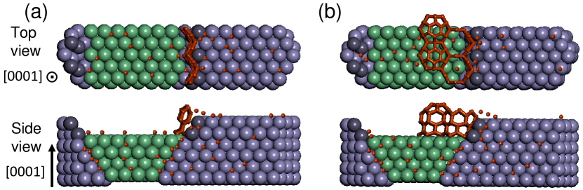
With the information at hand about the diffusion rates of the carbon feedstock, we proceed to discuss a possible growth scenario. The Co structure in Fig. 4 schematically depicts three grains, distinguished by color and shading. It is plausible to assume that the terrace height at both sides of the grain boundary may not be the same, yielding a step structure, which is best visible in side view. Under growth conditionsRodríguez-Manzo et al. (2011) near C, the fastest rate of carbon diffusion to the surface is along the grain boundary towards the step edge, where carbon may aggregate to a narrow graphene nanoribbon. Since according to our studies a zigzag edge binds more strongly to Co than an armchair edge, we consider a zigzag graphene nanoribbon attached to the step edge, as seen in Fig. 4(a). To best conform to the substrate, the nanoribbon acquires a washboard structure, depicted in the top panel in Fig. 4(a). The more reactive nanoribbon atoms, which protrude towards the terrace, are more likely to form bonds with carbon atoms diffusing along the terrace, thus initiating the formation of foam cells. In the meantime, atoms or flakes diffusing along the upper terrace become the feedstock for the termination of the foam layer by caps, as seen in Fig. 4(b). More detailed structure information and an animation of the growth process is presented in the EPAPS on-line materialEPA . We hope that this information may encourage follow-up experimental studies aiming at synthesizing the carbon foam and related carbon allotropes.
In conclusion, we studied the formation and structural as well as thermal stability of cellular foam-like carbon nanostructures by performing ab initio density functional calculations. We found that these systems with a mixed / bonding character may be compressed by reducing the symmetry of the honeycomb cells. The foam may accommodate the same type of defects as graphene, and its surface may be be stabilized by terminating caps. We postulate that the foam may form under non-equilibrium conditions near grain boundaries on a carbon-saturated Co surface and should be thermally stable up to K.
Acknowledgements.
We acknowledge extensive discussions with Florian Banhart, Julio A. Rodríguez-Manzo, and Arkady V. Krasheninnikov. This work was supported by the National Science Foundation Cooperative Agreement #EEC-0832785, titled “NSEC: Center for High-rate Nanomanufacturing”. Computational resources have been provided by the Michigan State University High Performance Computing Center.References
- Kroto et al. (1985) H. W. Kroto, J. R. Heath, S. C. O’Brien, R. F. Curl, and R. E. Smalley, Nature 318, 162 (1985).
- Iijima (1991) S. Iijima, Nature 354, 56 (1991).
- Novoselov et al. (2004) K. S. Novoselov, A. K. Geim, S. V. Morozov, D. Jiang, Y. Zhang, S. V. Dubonos, I. V. Grigorieva, and A. A. Firsove, Science 306, 666 (2004).
- Umemoto et al. (2001) K. Umemoto, S. Saito, S. Berber, and D. Tomanek, Phys. Rev. B 64, 193409 (2001).
- Kuc and Seifert (2006) A. Kuc and G. Seifert, Phys. Rev. B 74, 214104 (2006).
- Zhao et al. (2011) Z. Zhao, B. Xu, L.-M. Wang, X.-F. Zhou, J. He, Z. Liu, H.-T. Wang, and Y. Tian, ACS Nano 5, 7226 (2011).
- Enyashin and Ivanovskii (2011) A. N. Enyashin and A. L. Ivanovskii, Phys. Stat. Sol. (b) 248, 1879 (2011).
- Rodríguez-Manzo et al. (2011) J. A. Rodríguez-Manzo, C. Pham-Huu, and F. Banhart, ACS Nano 5, 1529 (2011).
- Rodriguez-Manzo et al. (2007) J. A. Rodriguez-Manzo, M. Terrones, H. Terrones, H. W. Kroto, L. Sun, and F. Banhart, Nature Nano. 2, 307 (2007).
- Lin et al. (2007) M. Lin, J. P. Y. Tan, C. Boothroyd, K. P. Loh, E. S. Tok, and Y.-L. Foo, Nano Lett. 7, 2234 (2007).
- Helveg et al. (2004) S. Helveg, C. Lopez-Cartes, J. Sehested, P. Hansen, B. Clausen, J. Rostrup-Nielsen, F. Abild-Pedersen, and J. Norskov, Nature 427, 426 (2004).
- Artacho et al. (2008) E. Artacho, E. Anglada, O. Dieguez, J. D. Gale, A. Garcia, J. Junquera, R. M. Martin, P. Ordejon, J. M. Pruneda, D. Sanchez-Portal, and J. M. Soler, J. Phys. Cond. Mat. 20, 064208 (2008).
- Ceperley and Alder (1980) D. M. Ceperley and B. J. Alder, Phys. Rev. Lett. 45, 566 (1980).
- Perdew and Zunger (1981) J. P. Perdew and A. Zunger, Phys. Rev. B 23, 5048 (1981).
- Troullier and Martins (1991) N. Troullier and J. L. Martins, Phys. Rev. B 43, 1993 (1991).
- Monkhorst and Pack (1976) H. J. Monkhorst and J. D. Pack, Phys. Rev. B 13, 5188 (1976).
- Kittel (2005) C. Kittel, Introduction to Solid State Physics, eighth ed. (Wiley, New York, 2005).
- Okada and Oshiyama (2003) S. Okada and A. Oshiyama, J. Phys. Soc. Jpn. 72, 1510 (2003).
- Higuchi et al. (2004) Y. Higuchi, K. Kusakabe, N. Suzuki, S. Tsuneyuki, J. Yamauchi, K. Akagi, and Y. Yoshimoto, J. Phys. Cond. Mat. 16, S5689 (2004).
- Mañanes et al. (2008) A. Mañanes, F. Duque, A. Ayuela, M. J. López, and J. A. Alonso, Phys. Rev. B 78, 035432 (2008).
- Hod and Scuseria (2008) O. Hod and G. E. Scuseria, ACS Nano 2, 2243 (2008).
- Kim et al. (2003) Y.-H. Kim, J. Choi, K. J. Chang, and D. Tomanek, Phys. Rev. B 68, 125420 (2003).
- Stone and Wales (1986) A. J. Stone and D. J. Wales, Chem. Phys. Lett. 128, 501 (1986).
- Thrower (1969) P. A. Thrower, in Chemistry and physics of carbon, Vol. 5, edited by P. L. Walker Jr. (Marcel Dekker, New York, 1969) pp. 217–320.
- Huang et al. (2011) P. Y. Huang, C. S. Ruiz-Vargas, A. M. van der Zande, W. S. Whitney, M. P. Levendorf, J. W. Kevek, S. Garg, J. S. Alden, C. J. Hustedt, Y. Zhu, J. Park, P. L. McEuen, and D. A. Muller, Nature 469, 389 (2011).
- Banhart et al. (2011) F. Banhart, J. Kotakoski, and A. V. Krasheninnikov, ACS Nano 5, 26 (2011).
- Meyer et al. (2008) J. C. Meyer, C. Kisielowski, R. Erni, M. D. Rossell, M. F. Crommie, and A. Zettl, Nano Lett. 8, 3582 (2008).
- Lahiri et al. (2010) J. Lahiri, Y. Lin, P. Bozkurt, I. I. Oleynik, and M. Batzill, Nature Nano. 5, 326 (2010).
- Tersoff (1988) J. Tersoff, Phys. Rev. Lett. 61, 2879 (1988).
- (30) See the supplementary information for molecluar dynamics simulations of the thermal stability of the foam and movies illustrating the growth mechanism.
- Gao et al. (2011) J. Gao, J. Yip, J. Zhao, B. I. Yakobson, and F. Ding, J. Am. Chem. Soc. 133, 5009 (2011).
- Li et al. (2010) B. Li, Q. Zhang, L. Chen, P. Cui, and X. Pan, Phys. Chem. Chem. Phys. 12, 7848 (2010).