Shaping Laguerre-Gaussian laser modes with binary gratings using a Digital Micromirror Device
Vitaly Lerner, David Shwa, Yehonathan Drori, and Nadav Katz
Abstract
Laguerre-Gaussian (LG) beams are used in many research fields, such as microscopy, laser cavity modes and optical tweezing. We develop a holographic method of generating pure LG modes (amplitude and phase) with a binary amplitude-only Digital Micromirror Device (DMD), as an alternative to the commonly used phase-only Spatial Light Modulator. The advantages of such a DMD include very high frame rates, low cost and high damage thresholds. We show that the propagating shaped beams are self-similar and their phase fronts are of helical shape as demanded. We estimate the purity of the resultant beams to be above 94%.
Racah Institute of Physics, Hebrew University of Jerusalem
Laguerre-Gaussian (LG) laser beam modes are solutions of the scalar Helmoltz equation under the paraxial approximation [1]. Since LG beam modes were shown to carry an angular momentum [2], they have been intensively investigated. LG modes are widely used in many research fields, including optical tweezing and atom guiding [3, 4], second-harmonic generation [5], quantum information and communication [6].
Much of the work done on beam shaping has been carried out recently with phase-only Spatial Light Modulators (SLMs)[7, 8, 9]. An alternative to this method is an amplitude control, using a Digital Micromirror Device (DMD). The most significant advantage of the DMD over Liquid Crystal on Silicon (LCoS) SLM is frame rate [10, 18]. LG modes have been generated using static amplitude holograms[11], while here we focus on programmable patterns. LG amplitude [12] and helical phase [13] have been generated separately using a DMD, while we focus on pure LG modes (both amplitude and phase).
Mathematically, LG modes are described in cylindrical coordinates, where we rescale by the beam width and corresponding Rayleigh range : . The width of all such Gaussian beams, at distance from the waist is . We can write the electric field of a LG mode [1] using generalized Laguerre polynomials , separated to amplitude and phase, omitting the global normalization constants and the global phase due to the propagation distance :
| (1) |
| (2) |
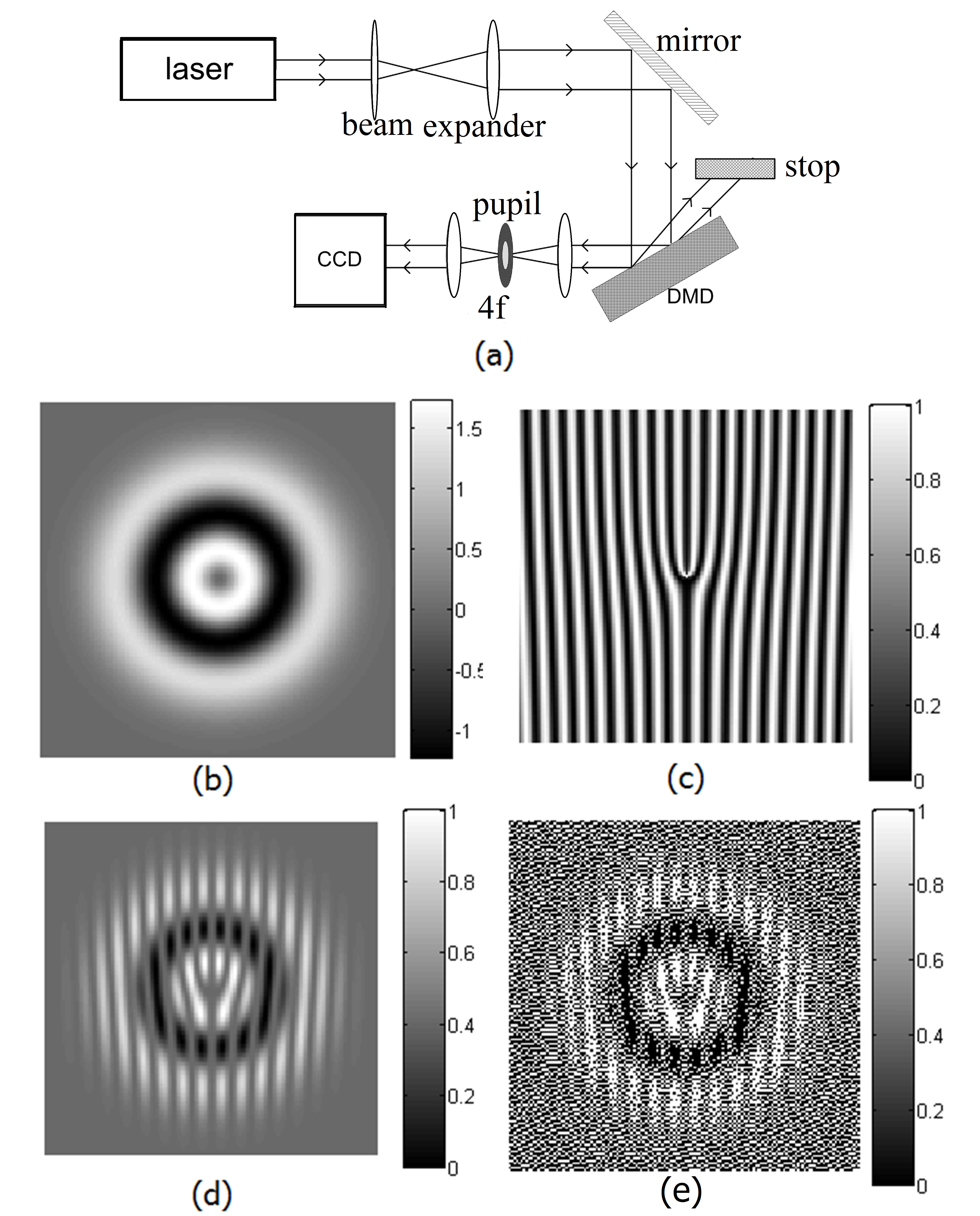
While shaping a phase front (Eq. (2) ) is a relatively simple procedure when using a phase-only SLM, e.g. LCoS, shaping an amplitude pattern is a matter of considerable algorithmic work[8]. In our case, the situation is opposite. We use an amplitude-only SLM. It is very easy to load a pattern on the DMD and to observe the same pattern at the imaging plane. However, a phase front cannot be created directly. A convenient technique [13, 14, 15, 11] to create light vortices of type is to use a fork-like pattern, e.g. Fig. 1(c). The pattern is a holographic interference of an LG beam with a unitary planar beam. Assuming that the angle between the beams is and the LG beam is at its waist (), the phase front becomes
| (3) |
The diffraction grating we use for creating such a front is
| (4) |
We use a commercial DMD device, adapted and mounted for optical experiments [16] The DMD consists of 480x320 micromirrors, each 7.6x7.6 microns in size. Each mirror corresponds to a certain pixel and it is held in either of two angular positions: (on, or “white” state) and (off, or “black”) state[21]. The DMD serves as a programmable spatial filter since the light reflected from and diffracted by the mirrors corresponding to the black pixels is filtered out (Fig. 1).
The maximal efficiency of a grey amplitude hologram is known to be , while for binary amplitude it can reach [19, 20]. Due to the complex three dimensional structure of the DMD surface, the pattern effectively consists of two gratings: the micromirrors grating-like structure and the information grating.When all pixels are on, at a particular angle, we concentrate more than 88% [21, 22] of the diffracted light into a single order.We measure an additional loss of about 40% of the total power of the incident beam. After applying the information grating between 1% and 5% of the incident beam intensity is concentrated in an output beam.
In order to obtain a desired pattern at the imaging plane, the first order beam is transferred and other diffraction beams are filtered out by the pupil (Fig. 1(a)). In our experiments 40cm away from the DMD the beams are well separated. However, in order to reproduce the near field, we use the imaging system.

Two optical vortices, i.e. diffractions of 1st orders can be are created by applying a fork-like pattern (Eq. (4), Fig. 1(c) ). A similar method is described in Ref. [13], where slow grey scale pixel modulation was used. However, in many applications stable vortex patterns are required. Therefore we avoid modulating pixels in time, and resort to pixel dithering [23]. The dithering leads to effective grey scale amplitude control.
The fork-like patterns are used to create vortices with no direct control of the amplitude. Ring-like amplitude has been achieved in previous works, e.g. [11], by -shifts at the zeros of LG radial component of amplitude distribution. We apply a different method, achieving significantly higher purity of the LG modes. We separate the beam shape to its amplitude and phase components (Eq. (1) and (3)). We multiply the fork-like pattern by the amplitude distribution and dither the resultant pattern (Fig. 1).
Previous works [11, 8] have shown that the purity of the LG modes was significantly affected by the ratio of the normalization radius of the hologram and the input Gaussian beam. Even at the optimal value of this ratio, the purity of the LG modes with was low when amplitude-only hologram was applied to Gaussian beam [11]. We optimize the purity of the output beams by changing the applied pattern:
| (5) |
, where is a correction parameter, is the width of the incident Gaussian beam, is the corrected width of the Gaussian envelope of the pattern and is the desired width of the shaped LG mode. The correction parameter can be calculated from measurements and substituted back to Eq. (5), but it should be fine-tuned empirically.
We measure a minimal radius at which there is no distortion of the resultant mode and a good off/on ratio to be 12 pixels (corresponding to about 90).
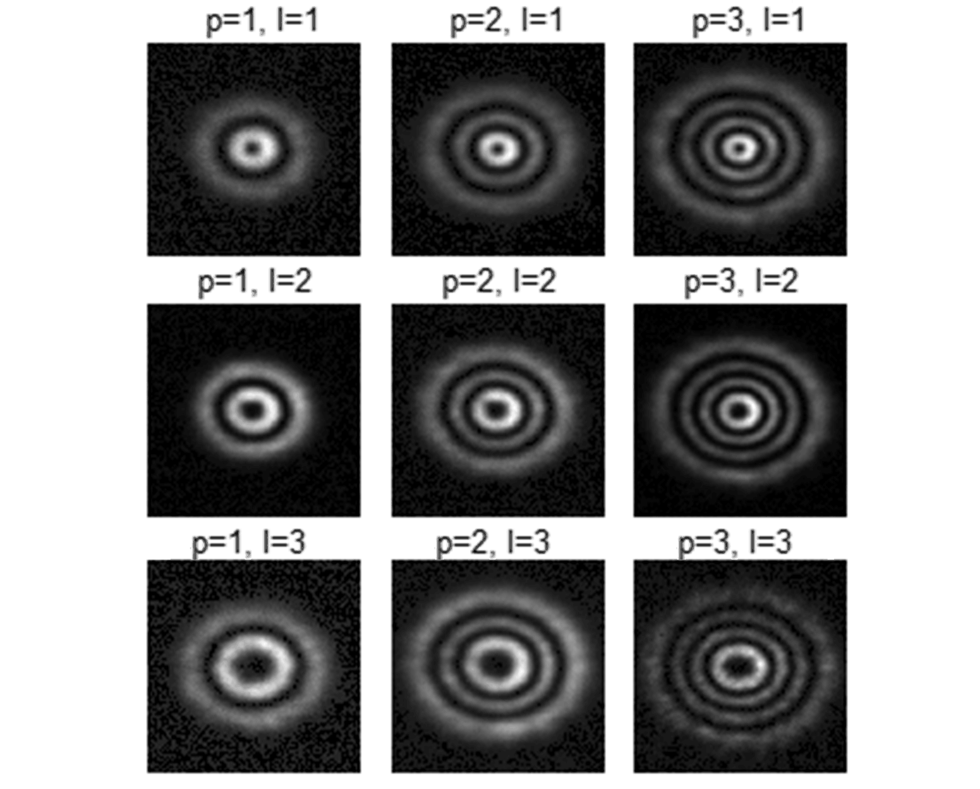
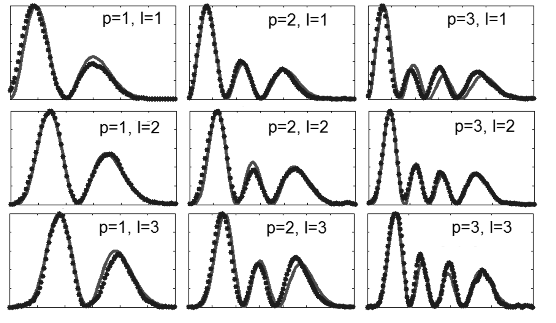
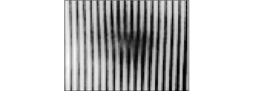
The results obtained at the imaging plane and in the near field show no significant difference from the far field, proving that the obtained modes are true LG modes (Eq. (1)) We present (Fig. 2) the results in far field [24]. In order to ensure that the far field is measured, and to focus the beam on the camera, we place a convex lens (f=20 cm) exactly 20 cm from the camera and 50 cm from the DMD. The Rayleigh range of the resultant beam was 12 cm. In order to study intensity profiles, we plotted cross-sections along with the ideal modes intensity profiles (Fig. 3). In order to confirm the helical phase front, the resultant beams are interfered with an off-axis Gaussian beam. The center of the resultant pattern is shown in Fig. 4, and its fork-like shape confirms [14] that in the far-field the beam has a helical phase front.


The experimental results fit almost perfectly the ideal intensity profiles. The off:on ratio (intensity at the origin divided by maximal intensity) varies between 1:100 and 1:1000.
In order to give a quantitative measure of the beams’ quality, we calculate mode purity in a manner similar to that of Ref. [9]. Since we do not measure directly either amplitude or phase (only intensity), we use a simulation of far-field Fraunhoffer diffraction to estimate the mode purity. As an input we use the same pattern loaded on the DMD multiplied by a Gaussian beam. Both simulation field and ideal one are normalized. We define purity as
| (6) |
The results for different modes vary from 95% () to 97% ().
A simpler direct correlation overlap of the experimental results (intensities) with the ideal intensities (see Fig. 3) yields slightly lower results, 94% to 96%. This indicates that experimentally we are very close to the optimal reachable result using this method.

In summary, we use a DMD as an amplitude-only SLM and demonstrate the shaping of Laguerre Gaussian modes. We achieve high purity, above 94%, of the modes, and we show that such purity is nearly optimal when applying our method. Further improvements may include employing a higher resolution DMD, and a fine adjustment of patterns in closed loop control.
We thank Nir Davidson and Hagai Eisenberg for helpful suggestions and discussion. This research was supported by ISF grant 1248/10.
References
- [1] M. Padgett and L. Allen, Opt. Commun. 121, 36-40 (1995).
- [2] L. Allen, M. Beijersbergen, R. Spreeuw and J. Woerdman, Phys. Rev. A 45, 81885-8189 (1992).
- [3] A. T. O’Neill and M. J. Padgett, Opt. Commun. 193, 45-50 (2001).
- [4] J. Arlt, T. Hitomi and K. Dholakia, Appl. Phys. B : Lasers and Optics 71, 549-554 (2000).
- [5] D. Petrov, Phys. Rev. A 82 (2010).
- [6] J. Torres, Y. Deyanova, L. Torner and G. Molina-Terriza, Phys. Rev. A 67 (2003).
- [7] L. Hu, L. Xuan, Y. Liu, Z. Cao, D. Li and Q. Mu, Opt. Express 12, 6403-6409 (2004).
- [8] N. Matsumoto, T. Ando, T. Inoue, Y. Ohtake, N. Fukuchi and T. Hara, J. Opt. Soc. Am. A 25, 1642-1651 (2008).
- [9] S. A. Kennedy, M. J. Szabo, H. Teslow, J. Z. Porterfield and E. R. I. Abraham, Phys. Rev. A 66, 043801 (2002).
- [10] J. Otona, M. S. Millana, P. Ambs and E. Perez-Cabrea, Proc. SPIE 7000, 70001V (2008).
- [11] J. Arlt, K. Dholakia, L. Allen and M. J. Padgett, J. Mod. Opt. 45, 1231-1237 (1998).
- [12] J. Liyang, ”High-precision laser beam shaping and image projection,” Ph.D. thesis (U. of Texas, 2012).
- [13] Y. X. Ren, M. Li, K. Huang, J. G. Wu, H. F. Gao, Z. Q. Wang and Y. M. Li, Appl. Opt. 49, 1838 (2010).
- [14] G. Molina-Terriza and J. Torres, Nature Physics 3, 305-310 (2007).
- [15] A. Bekshaev and O. Orlinska, Opt. Commun. 283, 1244 (2010).
- [16] We use a DMD mounted in Texas Instruments Pico DLP projector v.2 in a manner similar to that of [17]. We work at video rate since our goal was a proof-of-concept. Other control platforms, with higher [18] bandwidth are available.
- [17] F. Havermeyer, L. Ho and C. Moser, Opt. Express 19, 14642-14652 (2011).
- [18] F. P. Martial and N. A. Hartell, PLoS ONE 7, e43942(2012).
- [19] B. R. Brown and A. W. Lohmann, IBM Journal of Research and Development 13, 160 (1969).
- [20] A. Lohmann and D. P. Paris, Appl. Opt. 6, 1739 (1967).
- [21] L. A. Yoder, W. M. Duncan, E. M. Koontz, J. So, T. A. Bartlett, B. L. Lee, B. D. Sawyers, D. Powell and P. Rancuret, Proc. SPIE 4457, 54-61 (2001).
- [22] D. Dudley W. M. Duncan and J. Slaughter, Proc. SPIE 4985, 14 (2003).
- [23] R. W. Floyd and L. Steinberg, in International Symposium Digest of Technical Papers, Society for Information Displays, 36 (1975).
- [24] The barely observable elipticity is due to small imperfactions in our tilt angle adjustments, and input Gaussian beam. However, no splitting in l=2 and higher modes is observed indicating that this imperfection is negligable.