Anisotropic resistivity of Na1-δFe1-xCoxAs
Abstract
Temperature-dependent resistivity is studied in single crystals of iron-arsenide superconductor Na1-δFe1-xCoxAs for electrical current directions along, , and transverse, , to the Fe-As layers. Doping with Co increases stability of this compound to reaction with the environment and suppresses numerous features in both and compared to the stoichiometric NaFeAs. Evolution of with follows a universal trend observed in other pnictide superconductors, exhibiting a -linear temperature dependence close to the optimal doping and development of dependence upon further doping. in parent compound shows a non - monotonic behavior with a crossover from non-metallic resistivity increase on cooling from room temperature down to 80 K to a metallic decrease below this temperature. Both and show several correlated crossover - like features at 80 K. Despite a general trend towards more metallic behavior of inter - plane resistivity in Co-doped samples, the temperature of the crossover from insulating to metallic behavior (80 K) does not change much with doping.
pacs:
74.70.Dd,72.15.-v,74.25.JbI Introduction
Structurally, iron based superconductors are layered materials, in which FeAs (or iron chalcogenide) layer is the main building block for a variety of compounds paglione ; Johnston ; stewart . Since the dominant contribution to the density of states at the Fermi level comes from the iron 3d orbitals, one can expect a significant electronic anisotropy of the compounds revealed in the in-plane and out-of-plane transport. Contrary to this expectation, the most studied families of iron arsenides, those based on BaFe2As2, have rather low anisotropy ratio / 4 at anisotropy . In transition metal-doped Ba(Fe)2As2 (=Co, Ni, Rh, Pd, BaT122 in the following), also shows a very different temperature dependence compared with , revealing a broad crossover from non-metallic to metallic temperature dependence assigned in our systematic doping studies to the formation of a pseudogap anisotropy ; anisotropy2 ; pseudogap ; pseudogap2 .
Another interesting feature of iron arsenides that distinguishes them from the copper oxide based (cuprate) superconductors cupratesresistivity is a strong variation of the functional form of temperature-dependent resistivity for various types and levels of dopings. The general trend of evolution is the presence of a linear region immediately above for optimally doped compositions NDL ; WenK ; Kasahara ; NaFeAs . At higher temperatures this -linear behavior, for example in hole-doped Ba1-xKxFe2As2 and in self-doped Na1-δFeAs, is terminated by the pseudogap TanatarK ; NaFeAs .
Systematic studies of the temperature-dependent electrical resistivity are very important for the general understanding of superconductivity in this family of materials. Scattering in the normal state in the vicinity of the magnetic quantum critical point leads to the characteristic linear temperature dependence of , which then evolves towards Fermi-liquid behavior with doping (see Ref. [Louis, ] for a review). Deviations from this general behavior provide an insight into electronic and magnetic correlations Fernandes , in particular, into the mechanism of nematic state formation Fisher ; detwinning ; ECBK .
In this article we report the systematics of doping-evolution of in-plane and inter-plane resistivity of electron-doped Na1-δFe1-xCoxAs. This compound shows a “dome - like” phase diagram which is very similar to BaCo122 phaseDNaFeAs ; phaseD2NaFeAs ; NaFeAs . As such, this study brings additional insight into the scattering and correlation phenomena of the iron - based superconductors.
II Experimental
AC magnetic characterization of the samples was performed with a tunnel-diode resonator, (TDR)Vandegrift ; Prozorov2000 . Briefly, TDR is a self-oscillating tank circuit powered by a properly biased tunnel diode. The sample is mounted with Apiezon N-grease on a sapphire rod and is inserted in the inductor (coil). The sample temperature is controlled independent of the resonant circuit, which is actively stabilized at the constant temperature. The measured frequency shift is proportional to the differential magnetic susceptibility of the sample Prozorov2000 . In this work, for quick mounting and measurement protocols we used a simplified version of the TDR susceptometer (a “dipper”), which is inserted directly into a transport 4He dewar and gives very quick turn-around measurement time of typically 30 minutes per sample. The trade-off of this quick measurement protocol is reduced stability and higher temperature-dependent background as compared to our high-stability 3He and dilution refrigerator versions of the TDR susceptometer. Nevertheless, the “dipper” is perfectly suitable to study magnetic signature of the superconducting transition.
Single crystals of Na(Fe1-xCox)As with 0, 0.025, 0.05, 0.08, and 0.10 were synthesized by sealing a mixture of Na, Fe, As, and Co together in Ta tubes and heating it to 950 ∘C, followed by 5 ∘C/hour cooling down to 900 ∘C He2010PRL . The in samples was defined as the nominal ratio, which gives some variation with electron-probe microanalysis values XHChenNaFeAs ; ShiyanNaFeAs . The samples were stored and transported in sealed containers filled with inert gas.
Sample preparation was done quickly in air within about 5 minutes to minimize uncontrolled environmental exposure which can induce an increase of Todorov2010CM ; NaFeAs . We started sample preparation by cleaving slabs from the inner part of the crystals with typical a thickness of 50 to 100 m. The slabs had shiny cleavage surfaces and were further cut into smaller pieces for TDR (typically 0.50.5mm2) and resistivity measurements. Cleaved internal parts of single crystals did not show any visible reaction with air and turned out to be relatively stable, contrary to crystals with the residue of NaAs flux, which aggressively reacts with air and moisture. After preparation, samples were promptly measured and immediately stored after measurements in inert and dry environment. After each dipper run samples were washed with toluene to remove remaining N-grease in order to control the air exposure.
Samples for in-plane resistivity measurements had typical dimensions of (1-2)0.5(0.02-0.1) mm3. All sample dimensions were measured with an optical microscope with an accuracy of about 10%. Sample resistivity at room temperature, , was in the range 400 to 500 for all compositions studied. This value is obtained on a bigger array of samples than in our previous study NaFeAs and is somewhat higher. It is also somewhat higher than values found in electron- Alloul ; pseudogap and hole-doped WenK Ba122 compounds, typically 300 or less. We do not have sufficient array of data to obtain lower error bars needed to resolve the doping evolution of , if any exists. Contacts for four-probe resistivity measurements were made by soldering 50 m silver wires with ultra-pure Sn solder, as described in Ref. [SUST, ]. Resistivity measurements were performed in PPMS, providing magnetic fields up to 9 T. For measurements of the upper critical field, , samples were glued to the side of a plastic block with plane of the sample oriented to be either parallel or perpendicular to the direction of magnetic field (with an accuracy of about 1∘).
Inter-plane resistivity measurements were done using the two-probe technique, relying on very low contact resistance of soldered contacts, typically in the 10 range. The top and bottom surfaces of the -plane (typically 0.50.5mm2 area) of the samples were covered with Sn solder forming a capacitor-like structure. A four-probe scheme was used to measure a sample with contacts, giving a sum of series connected sample, , and contact resistance, resistances. Since , contact resistance represents a minor portion, on the order of 1-5% on the total resistance. This can be directly seen for our samples for temperatures below the superconducting , where 0 and the measured resistance represents anisotropy ; SUST ; vortex . Further details of the measurement procedure can be found in Refs. anisotropy, ; anisotropy2, ; pseudogap, .
The drawback of the measurement of samples with is that any structural and chemical inhomogeneity along the axis, a very common problem in soft and micaceous samples of iron arsenide superconductors NiNiCo ; anisotropy ; Bobkowski , not only increases sample resistance, but admixes in-plane component due to the redistribution of the current. One way to ascertain correctness of the measurements, is to rely on measurements with the lowest resistivity values. Typically the best results were obtained on the thinnest slabs. To get reliable results we performed measurements of on at least 5 samples of each batch. In all cases we obtained qualitatively similar temperature dependences of the normalized electrical resistivity, . The resistivity value at room temperature, , however, showed a notable scatting and was typically in the range 2000 to 3000 cm at room temperature.
We have shown previously that reaction with air strongly affects the value of due to the development of cracks NaFeAs . Cracks grossly effect the internal sample connectivity and, hence, homogeneous current distribution, thus, making inter-plane resistivity measurements of environmentally exposed samples impossible.
III Results
III.1 Environmental stability
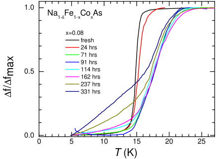
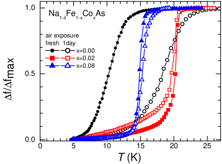
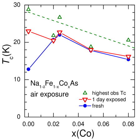
The of the parent Na1-δFeAs increases significantly upon exposure to air Chu ; NaFeAs , water Todorov2010CM and Apiezon N-grease NaFeAs . Here, we study how the sensitivity of to exposure changes with Co- doping. In Fig. 1 we show the evolution of the TDR signal in slightly overdoped, =0.08 (fresh sample =16 K), samples on exposure to air. Similar to the parent compound NaFeAs , for all compositions irrespective of their , the of the samples increases initially upon air exposure and then decreases with prolonged exposure. The doping-variation of TDR signal during fixed time, one day air exposure, is summarized in Fig. 2. Variation of fresh sample and highest achieved during air exposure and fixed - time of one day exposure as a function of are summarized in Fig. 3.
One day exposure of a sample to air does not lead to a visual appearance of reaction products. Thus, at least at this initial stage, there is no reason to assume transformation of NaFeAs into NaFe2As2, the final product of reaction with water Todorov2010CM , formed after one a month exposure, which most likely shows up in Fig. 1 as a new shoulder in the temperature dependent frequency shift at about 12 K for samples exposed for about two weeks.
In parent Na1-δFeAs the environmental reaction is caused by the variation of Na content in the samples, , due to oxidative deintercalation Todorov2010CM . It is natural to expect similar effect in the Co - doped NaFe1-xCoxAs. However, the puzzling observation is that increases for both environmental reaction in pure Na1-δFeAs (presumably hole - like doping) and electron Co - doping. As such, it is not clear if carrier type and density change is the main effect involved. We note that detailed study of the effect of Li deficiency in a closely related LiFeAs superconductor found suppression of , but virtually no change in the normal - state properties LiDeficiency . If Na deficiency leads to the formation of Na vacancies, this should lead to hole doping and, thus, move the dome on the doping phase diagram in an opposite way to electron Co-doping. Further studies are required to understand what type of doping is induced by the loss of Na and what types of defects are formed.
At a first glance, the different rate of variation in Fig. 3 can be attributed to the different sensitivity of in different parts of the phase diagram - being smallest at the flat optimal doping region. Indeed, the slope of changes from very high for the parent compound to negligible in samples close to optimal doping. However, we find a rise in after environmental reaction even in over-doped samples. This contradicts the simple relation of the rate of change to be determined by a position on the phase diagram. Our observations rather support previous observation XHChenNaFeAs that Co doping increases the stability of the samples.
III.2 Resistivity measurements
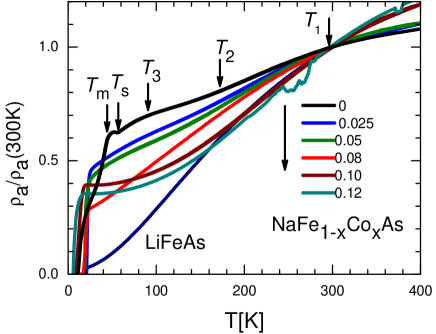
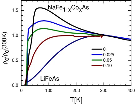
The temperature-dependent resistivity of “fresh” crystals of NaFe1-xCoxAs is shown in Fig. 4 using a normalized resistivity scale, . The shape of in the parent compound is relatively complex, with features due to split structural (at temperature =55 K) and magnetic (at =45 K) transitions phaseDNaFeAs ; DaiNaFeAs and slope changes at higher temperatures NaFeAs ; nematicNaFeAs . With doping the dependence transforms to very close to -linear in samples with =0.08 and close to on further increase. The changes of slope at 300 K (increase of slope on cooling), 160 K (decrease of slope on cooling), and 80 K (increase of slope on cooling) are observed in doped samples, similar to the parent compound, and are relatively insensitive to doping. The feature at is observed in samples with all studied. It is similar, though less pronounced, to a slope change at about the same temperature in of stoichiometric LiFeAs, see Fig. 4. The features at and are observed in of the samples with 0.05.
The results of this study of are in reasonable agreement with previous studies on single crystals nematicNaFeAs ; XHChenNaFeAs , with the difference of coming from using nominal values during sample preparation. The doping-transformation of the temperature dependent resistivity for right above follows general expectations for a quantum critical scenario NDL , with -linear range confined from high temperature side by slope change on approaching . By comparison with position of maximum in the temperature dependent inter-plane resistivity , we assigned similar slope change feature in of Ba1-xKxFe2As2 to formation of pseudogap TanatarK . The slope changes upon cooling through and in samples with 0.05 do not have a direct analogy with Ba122 compounds. These features are observed even in samples in which long-range magnetic order and orthorhombic structural distortion are suppressed. Studies of resistivity anisotropy on detwinned single crystals of parent NaFeAs nematicNaFeAs suggest that the feature at has a similar nature to nematic correlations, which is particularly strong in electron doped BaCo122 Fisher ; detwinning .
For understanding the resistivity of NaFeAs based compounds, it is important to get insight into the temperature dependence of the inter-plane resistivity component. In Fig. 5 we show the doping evolution of in NaFe1-xCoxAs. The inter-plane resistivity of parent NaFeAs increases during cooling down to a maximum at 70 K, which is close to as determined from . The resistivity rapidly decreases below this maximum, with a notable rate increase below . Note that contrary to , the inter-plane resistivity does not show an increase below , suggesting that the carriers affected by the formation of a gap do not contribute much to the inter-plane transport. Interestingly, despite the strong difference between and , the high temperature features are observed in both of them.
III.3 Anisotropy of the upper critical field
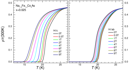
The anisotropy of the electrical resistivity at , , is linked with the anisotropy of the upper critical field, , with . Because determination of the absolute values in resistivity measurements always includes uncertainty of the geometric factor and is affected by the cracks, the anisotropy measurements provide an alternative way to evaluate resistivity anisotropy anisotropy . In Fig. 6 we zoom the superconducting transition in in-plane resistivity measurements for a sample with doping level close to optimal, =0.025. The same sample was remounted on a plastic cube with the magnetic field was in the (left panel) and (right panel) configurations.
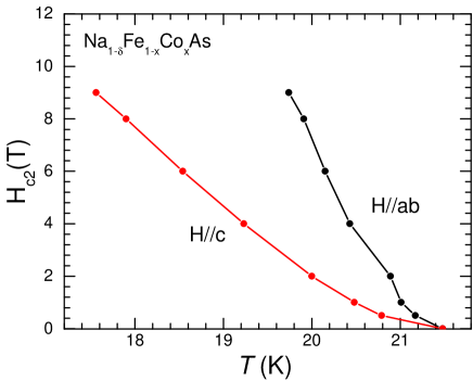
We used the resistive transition midpoint to determine anisotropy as shown in Fig. 7. Close to the anisotropy =2.25 for the sample with =0.025. Similar value with =2.35 was obtained in sample with =0.08. These measurements suggest a resistivity anisotropy of about 5 at . Considering that (see Figs. 4 and 5) we expect a negligible anisotropy of 2 to 3 at room temperature. The direct resistivity measurements, with =400 to 500 cm and =2000 to 3000 cm, suggest an anisotropy of 4 to 8. The origin of this factor of about two discrepancy remains unclear at the moment.
IV Discussion
IV.1 Slope-change features in the temperature-dependent resistivity
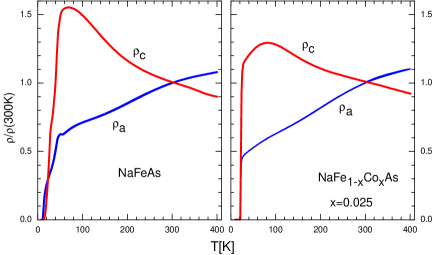
As can be seen from direct comparison of in-plane and inter-plane resistivity in the parent and slightly doped =0.025 compositions, Fig. 8, features in find counterparts in . For example, a slope decrease in generally metallic below 160 K is seen as slope increase in generally activated (increasing on cooling) . This similarity found in two very different dependences suggests that the activation of carriers over a partial gap, rather than change of scattering, is responsible for the feature. Partial (nematic) order nematicNaFeAs , which happens above the structural transition at , changes from insulating to metallic, while the magnetic order below causes a dramatic decrease of resistivity in both directions of charge flow. The decrease is especially strong in the parent compound in which the residual resistivity ratio (RRR), , is a factor of two higher than in =0.025. These observations suggests that magnetic scattering plays an important role in resistivity at , and that when inelastic scattering is dominant (as in the parent compound) taming down of magnetic fluctuations reveals intrinsically very low residual resistivity.
IV.2 Residual resistivity
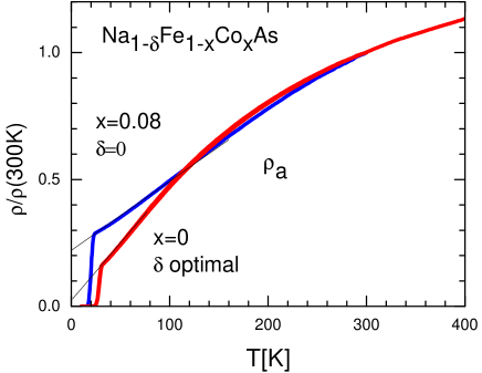
Observation of a much higher RRR in non-doped materials agrees with studies in Ba122 compounds, though in the latter, the direct comparison is not so simple. In the case of NaFeAs based materials we can compare RRR of the samples, brought to optimal doping using two different doping, electron with Co substitution of Fe and environmental, on interaction with the environment. In Fig. 9 we compare -dependent resistivity in two concentrations of samples, extrapolating curves linearly from to . The RRR ratio decreases from more than 20 in environmentally doped samples to about 4 in Co-doped samples. Taking that resistivity at room temperature does not change from about 400 cm , this suggests that the residual resistivity induced by the =0.025 substitution of Fe atoms with Co is on the order of 100 cm, comparable to BaCo122 pseudogap . This is almost a factor of five higher than the value found in very disordered samples, doped with environmental reaction, which extrapolates to 20 cm.
V Conclusions
In conclusion, we find that the complicated shape of the temperature dependent inter-plane resistivity of both parent NaFeAs and Co - doped NaFe1-xCoxAs shows the same anomalies as in-plane resistivity. This is particularly interesting considering the fact that inter-plane transport is clearly thermally activated, while the in - plane resistivity follows metallic decrease on cooling. This finding suggests that the observed features are not caused by a particular type of scattering process and most likely are determined by the variation in the carrier density. Such behavior strongly supports the idea that these features are caused by the thermal activation of charge carriers over the pseudogap in the electronic spectrum. This conclusion suggests that the pseudogap is a common feature of both NaFeAs - based materials and BaFe2As2 - derived compounds pseudogap ; pseudogap2 ; BasovPseudogap .
VI Acknowledgements
We thank Seyeon Park for her help with dipper measurements. Work at the Ames Laboratory was supported by the Department of Energy-Basic Energy Sciences under Contract No. DE-AC02-07CH11358. The single crystal growth effort at UT is supported by U.S. DOE BES under Grant No. DE-FG02-05ER46202 (P.D.).
References
- (1) Johnpierre Paglione and Richard L. Greene, Nature Phys. 6, 645 (2010).
- (2) D. C. Johnston, Adv. Phys. 59, 803 (2010).
- (3) G. R. Stewart, Rev. Mod. Phys. 83, 1589 (2011).
- (4) M. A. Tanatar, N. Ni, C. Martin, R. T. Gordon, H. Kim, V. G. Kogan, G. D. Samolyuk, S. L. Bud’ko, P. C. Canfield, and R. Prozorov, Phys. Rev. B 79, 094507 (2009).
- (5) M. A. Tanatar, N. Ni, G. D. Samolyuk, S. L. Bud’ko, P. C. Canfield, and R. Prozorov, Phys. Rev. B 79, 134528 (2009)
- (6) M. A. Tanatar, N. Ni, A. Thaler, S. L. Bud’ko, P. C. Canfield, and R. Prozorov, Phys. Rev. B 82, 134528 (2010).
- (7) M. A. Tanatar, N. Ni, A. Thaler, S. L. Bud’ko, P. C. Canfield, and R. Prozorov, Phys. Rev. B 84, 014519 (2011).
- (8) See, for example, N. Hussey, J. Phys: Condens. Matter 20, 123201 (2008).
- (9) N. Doiron-Leyraud, P. Auban-Senzier, S. René de Cotret, C. Bourbonnais, D. Jérome, K. Bechgaard, and L. Taillefer, Phys. Rev. B 80, 214531 (2009).
- (10) Bing Shen, Huan Yang, Zhao-Sheng Wang, Fei Han, Bin Zeng, Lei Shan, Cong Ren, and Hai-Hu Wen, Phys. Rev. B 84, 184512 (2011).
- (11) S. Kasahara, T. Shibauchi, K. Hashimoto, K. Ikada, S. Tonegawa, R. Okazaki, H. Shishido, H. Ikeda, H. Takeya, K. Hirata, T. Terashima, and Y. Matsuda, Phys. Rev. B 81, 184519 (2010).
- (12) M. A. Tanatar, N. Spyrison, Kyuil Cho, E. C. Blomberg, Guotai Tan, Pengcheng Dai, Chenglin Zhang, and R. Prozorov, Phys. Rev. B 85, 014510 (2012).
- (13) M. A. Tanatar, E. C. Blomberg, Hyunsoo Kim, Kyuil Cho, W. E. Straszheim, Bing Shen, Hai-Hu Wen, R. Prozorov, arXiv:1106.0533
- (14) L. Taillefer, Ann. Rev. Condensed Matter Physics 1, 51 (2010).
- (15) R. M. Fernandes, A. V. Chubukov, J. Knolle, I. Eremin, and J. Schmalian, Phys. Rev. B 85, 024534 (2012).
- (16) Jiun-Haw Chu, J. G. Analytis, K. De Greve, P. L. McMahon, Z. Islam, Y. Yamamoto, and I. R. Fisher, Science 329, 824 (2010).
- (17) M. A. Tanatar, E. C. Blomberg, A. Kreyssig, M. G. Kim, N. Ni, A. Thaler, S. L. Bud’ko, P. C. Canfield, A. I. Goldman, I. I. Mazin, and R. Prozorov, Phys. Rev. B 81, 184508 (2010).
- (18) E. C. Blomberg, M. A. Tanatar, R. M. Fernandes, Bing Shen, Hai-Hu Wen, J. Schmalian, and R. Prozorov, arXiv:1202.4430.
- (19) D. R. Parker, M. J. P. Smith, T. Lancaster, A. J. Steele, I. Franke, P. J. Baker, F. L. Pratt, M. J. Pitcher, S. J. Blundell, and S. J. Clarke, Phys. Rev. Lett. 104, 057004 (2010).
- (20) J. D. Wright, T. Lancaster, I. Franke, A. J. Steele, J. S. Müller, M. J. Pitcher, A. J. Corkett, D. R. Parker, D. G. Free, F. L. Pratt, P. J. Baker, S. J. Clarke, and S. J. Blundell Phys. Rev. B 85, 054503 (2012).
- (21) C. He, Y. Zhang, B. P. Xie, X. F. Wang, L. X. Yang, B. Zhou, F. Chen, M. Arita, K. Shimada, H. Namatame, M. Taniguchi, X. H. Chen, J. P. Hu, and D. L. Feng, Phys. Rev. Lett. 105, 117002 (2010).
- (22) A. F. Wang, X. G. Luo, Y. J. Yan, J. J. Ying, Z. J. Xiang, G. J. Ye, P. Cheng, Z. Y. Li, W. J. Hu, and X. H. Chen, Phys. Rev. B 85, 224521 (2012).
- (23) S. Y. Zhou, X. C. Hong, X. Qiu, B. Y. Pan, Z. Zhang, X. L. Li, W. N. Dong, A. F. Wang, X. G. Luo, X. H. Chen, and S. Y. Li, arXiv:1204.3440.
- (24) C. T. Vandegrift, Rev. Sci. Instr. 46, 599 (1975).
- (25) R. Prozorov, R. Giannetta, A. Carrington, and F. Araujo-Moreira, Phys. Rev. B 62, 115 (2000).
- (26) I. Todorov, D. Y. Chung, H. Claus, C. D. Malliakas, A. P. Douvalis, T. Bakas, J. Q. He, V. P. Dravid, and M. G. Kanatzidis, Chem. Mater. 22, 3916 (2010).
- (27) F. Rullier-Albenque, D. Colson, A. Forget, and H. Alloul, Phys. Rev. Lett. 103, 057001 (2009).
- (28) M. A. Tanatar, N. Ni, S. L. Bud’ko, P. C. Canfield, and R. Prozorov, Supercond. Sci. Technol. 23, 054002 (2010).
- (29) R. Prozorov, N. Ni, M. A. Tanatar, V. G. Kogan, R. T. Gordon, C. Martin, E. C. Blomberg, P. Prommapan, J. Q. Yan, S. L. Bud’ko, and P. C. Canfield, Phys. Rev. B 78, 224506 (2008).
- (30) N. Ni, M. E. Tillman, J.-Q. Yan, A. Kracher, S. T. Hannahs, S. L. Bud’ko, and P. C. Canfield, Phys. Rev. B 78, 214515 (2008).
- (31) Meng Wang, Miaoyin Wang, Hu Miao, S.V.Carr, D.L.Abernathy, M.B.Stone, X.C.Wang, Lingyi Xing, C.Q.Jin, Xiaotian Zhang, Jiangping Hu, Tao Xiang, Hong Ding, Pengcheng Dai, arXiv:1208.0909 (2012).
- (32) J. S. Bobowski, J. C. Baglo, James Day, P. Dosanjh, Rinat Ofer, B. J. Ramshaw, Ruixing Liang, D. A. Bonn, W. N. Hardy, Huiqian Luo, Zhao-Sheng Wang, Lei Fang, and Hai-Hu Wen, Phys. Rev. B 82, 094520 (2010).
- (33) K. Sasmal, B. Lv, Z. J. Tang, F. Chen, Y. Y. Xue, B. Lorenz, A. M. Guloy, and C. W. Chu, Phys. Rev. B 79, 184516 (2009).
- (34) Y. J. Song, J. S. Ghim, B. H. Min, Y. S. Kwon, M. H. Jung, and J.-S. Rhyee, Appl. Phys. Lett. 96, 212508 (2010)
- (35) M. A. Tanatar, J.-Ph. Reid, S. Ren de Cotret, N. Doiron-Leyraud, F. Lalibert, E. Hassinger, J. Chang, H. Kim, K. Cho, Yoo Jang Song, Yong Seung Kwon, R. Prozorov, and Louis Taillefer, Phys. Rev. B 84, 054507 (2011).
- (36) Shiliang Li, Clarina de la Cruz, Q. Huang, G. F. Chen, T.-L. Xia, J. L. Luo, N. L. Wang, and Pengcheng Dai, Phys. Rev. B 80, 020504 (2009).
- (37) Y. Zhang, C. He, Z. R. Ye, J. Jiang, F. Chen, M. Xu, Q. Q. Ge, B. P. Xie, J. Wei, M. Aeschlimann, X. Y. Cui, M. Shi, J. P. Hu, and D. L. Feng, Phys. Rev. B 85, 085121 (2012).
- (38) S. J. Moon, A. A. Schafgans, S. Kasahara, T. Shibauchi, T. Terashima, Y. Matsuda, M. A. Tanatar, R. Prozorov, A. Thaler, P. C. Canfield, A. S. Sefat, D. Mandrus, and D. N. Basov, Phys. Rev. Lett. 109, 027006 (2012).