Direction dependency of extraordinary refraction index in uniaxial nematic liquid crystals
Abstract
The article presents a straightforward experiment that directly and illustratively demonstrates double refraction. For this purpose, two liquid crystalline cells were designed, which enable qualitative and quantitative measurements of the extraordinary refractive index direction dependency in a uniaxial nematic liquid crystal.
I Teaching the concept of anisotropy
When a physical property in the material varies with the direction, the material is said to be anisotropic. Anisotropy of physical properties is a crucial property of materials that are nowadays extremely important in science and technology. An example of such materials involves the liquid crystals that enable production of several devices used in everyday life (flat-screen TVs, notebooks, iPads, calculators, etc.). Even though students are in touch with such devices on a daily basis, they are not aware of anisotropy as a key property of the materials that enable the hi-tech products they use so eagerly. This ignorance might be due to the fact that the concept of anisotropy and in particular its consequences are rather difficult to comprehend. nclc ; knitting It is thus important to introduce the concept of anisotropy as soon as possible, taking into account students’ knowledge of physics and mathematics. ciferno ; Pavlin ; pieranski
In this paper we focus on birefringence as one of the most widely used properties of anisotropic materials. In a birefringent material there are two distinct waves that can propagate in a general direction determined by the wave vector direction (). The two waves are linearly polarized, their polarizations being perpendicular. They travel with different phase velocities, which means that the indices of refraction are different for the two waves although their wave vectors are in the same direction. Both refractive indices depend on the direction of .
An important property of light propagation in anisotropic materials is that the energy (defined by the Poynting vector , where is the electric and the magnetic field) does not propagate in the same direction as the wave vector (i.e., the wave fronts propagate in a different direction than the energy). The ray that we see is the direction of energy propagation. So, in order to avoid confusion, one should strictly state which velocity is considered (phase or ray velocity), and when considering the direction of light propagation, state whether the ray or wave vector direction is being considered.
In a general anisotropic medium there are two directions of wave vector propagation, along which the two waves travel with the same phase velocity. These two directions are called the optic axes, and the material is said to be biaxial. In the biaxial material there are also two directions, along which the ray velocities for both waves are equal. These axes are called the ray axes and are distinct from the optic axes. When optic axes are identical, material is uniaxial. In uniaxial materials the optic and the ray axes are the same. In optically uniaxial materials the phase and ray velocities of one of the two waves are equal, independent of the direction of propagation. This wave is called the ordinary wave. For the second wave, the phase and ray velocities are different in magnitude and direction, and they both depend on the direction of propagation. This wave is called the extraordinary wave.
The most easily observed and striking optical property of transparent anisotropic materials is double refraction (birefringence): the light incident on the interface between the isotropic and anisotropic material refracts into the anisotropic material in such a way that there are in general two rays of light propagating through the material in different direction; the light in both rays is polarized (even if the incident light is not polarized); light polarizations in the two rays are perpendicular.
Double refraction is usually demonstrated by observing the doubling of a text observed through the calcite. calcite When a polarizer is placed behind the calcite (or in front of it), one of the figures disappears if the polarizer’s transmission direction coincides with the polarization of the transmitted light. Although the explanation for this phenomenon is rather straightforward for a trained physicist, it is usually not so easily comprehended by students. A more straightforward experiment demonstrates the splitting of the unpolarized incident light beam into two beams of linearly polarized light. One needs a large birefringent crystal that is thick enough so that two transmitted beams can be observed as two light spots on a distant screen. By changing the direction of the incident light by rotating the crystal, one can observe the direction dependency of the extraordinary wave refractive index in uniaxial crystals, as well as the direction dependency of both indices in biaxial crystals. Unfortunately, the accuracy of quantitative measurements for both indices is poor, as any, even slight non-parallelism of the crystal surfaces results in a significant change in the transmitted light direction. Since the most easily accessible crystals are biaxial (e.g., quartz), this additionally complicates the comparison of the experimental results and the theoretical considerations.
Liquid crystals are optically anisotropic materials that are easy and cheap to obtain; even more, they can be synthesized in a school laboratory, not only at the university level but also at the high school level. Liberko ; Verbit ; Wright ; Pavlin By using liquid crystals, the concept of anisotropy can be qualitatively introduced even at the elementary school level. At the high school level, anisotropic properties can be introduced through a set of carefully designed experiments. The concept can be efficiently reinforced at the university level, with an interdisciplinary teaching module consisting of lectures and lab work.Pavlin ; Eurasia The module is appropriate for both social and natural science students. While such a teaching module has proven to be very efficient in achieving the conceptual understanding of optical anisotropy, Physics students also require experiments that allow quantitative measurements. Liquid crystals offer a possibility to measure angular dependency of the refractive index in uniaxial materials. In this paper we present an experiment that enables quantitative measurements of the refractive index for light propagating at angles ranging from to with respect to the optic axis.
II Propagation of light in anisotropic media
In an anisotropic dielectric material, the polarization () in the material depends on the direction of the external electric field (), and it is, in general, not in the direction of the external field. This property is described by the electric susceptibility () being a tensor quantity (not scalar, as in isotropic materials), and the relation between the material polarization and the electric field is:
| (1) |
Light is the propagation of an electromagnetic wave. The electric field in the electromagnetic wave interacts with the material and induces polarization, which varies over time with the same frequency as the frequency of light. Interaction of light with matter reduces the speed of light. In materials where the field induced polarization is larger (materials with greater electric susceptibility), the speed of light is lower. The ratio between the speed of light in a vacuum and in a particular material is given by the index of refraction. Since in anisotropic materials polarization in the material depends on the direction of the external electric field, in such materials the index of refraction varies with the direction of light propagation, and it depends on the direction of the electric field (i.e., the direction of light polarization). We point out that polarization of light (direction of in light) should not be confused with material polarization (), which is a result of in light. The reader should once again carefully examine Eq. (1) to fully grasp the difference.
Propagation of light is described by the wave equation. We shall assume a nonmagnetic material (no magnetization due to the external magnetic field) that contains no volume charge and no conducting current. Assuming a monochromatic plane wave with frequency propagating in any direction given by the wave vector , the electric and magnetic field vectors may be described by the harmonic representation, e.g. . The general plane wave equation in the anisotropic media is nasvet-valen
| (2) |
where is the magnitude of the wave vector in a vacuum, and is the dielectric tensor; it is the sum of an identity tensor and the electric susceptibility. For ordinary nonabsorbing materials the dielectric tensor is symmetric, so there always exists a coordinate system with a set of axes, called the principal axes, in which the dielectric tensor is diagonal. In optically uniaxial materials with the optic axis in the -direction, the - and -components of the dielectric tensor are equal:
| (3) |
where is called the ordinary and the extraordinary index of refraction. We shall solve the wave equation only for a special case of the wave vector direction, assuming that the wave vector is in the -plane: . For the electric field, we assume a general direction . One cannot assume that the electric field is perpendicular to the wave vector, since such orthogonality is valid only in isotropic materials. Using the ansatz for and and the expression (3) for the dielectric tensor, a set of three equations is obtained from the wave equation (Eq. (2)):
| (4) |
| (5) |
| (6) |
The nontrivial solutions of the set of Eqs. (4) - (6) are obtained if the determinant of the coefficients in front of is zero. The determinant is zero if one of the conditions
| (7) |
or
| (8) |
is satisfied.
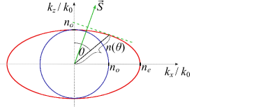
The condition (7) gives the magnitude of the wave vector in the anisotropic material, a magnitute that is the same for all directions of propagation in the -plane. This solution presents the ordinary wave. The refractive index for the ordinary wave is isotropic and equal to . Eq. (8) presents the constraint on the magnitude of the wave vector of the extraordinary wave. The allowed magnitudes of the wave vectors lie on an ellipse for the extraordinary wave and on a circle for the ordinary wave (Fig. 1). When rotated around the optic axis, the circle draws the surface of a sphere, and the ellipse the surface of an ellipsoid; we thus obtain the wave vector surfaces, giving us the magnitude of the wave vector for light propagation in a general direction. The reader is referred to any book in modern optics to prove this, or he/she can check it on his own by choosing different planes of wave vector direction (for example, to the already studied -plane, consider also the - and the -plane).
Expressing the magnitude of the wave vector of the extraordinary wave as , where is the index of refraction of the extraordinary wave for the light propagating with the wave vector at an angle with respect to the optic axis, the wave vector can be expressed as . Using this expression, the angular dependence of the index of refraction can be derived from Eq. (8):
| (9) |
The ordinary and extraordinary waves are linearly polarized. By using the condition (7) in Eqs. (4) - (6), we find that and . The ordinary wave is thus linearly polarized in the -direction, i.e. in the direction perpendicular to the plane defined by the optic axis and the wave vector. When the condition (8) is used in Eqs. (4) - (6), we find that while and can be different from zero. The polarization of the extraordinary wave is in the plane defined by the optic axis and the wave vector and is thus perpendicular to the polarization of the ordinary wave. From Eqs. (4) and (6), it is straightforward to show that the polarization of the extraordinary wave is along the -axis if is along the -axis and vice versa. To find the direction of in the extraordinary wave with at a general angle with respect to the optic axis, is more elaborate. So we state without a proof that is always in the direction tangential to the ellipse. The direction of the ray (meaning the direction of the energy propagation and the direction of the ray velocity) at a given direction of (the direction of the phase velocity) is shown in Fig. 1. The difference in the two directions is obvious. However, one must bear in mind that even in materials with large anisotropy, the ratio between the ordinary and the extraordinary index is of the order of 10 %, so the actual difference in the direction of propagation of and is much smaller. In calcite , in quartz and in liquid crystals, where the anisotropy is very large, for the liquid crystal used in the experiment presented in this paper.
II.1 Double refraction
When a beam of unpolarized light is incident on the anisotropic uniaxial transparent medium, it refracts into two beams. The direction of the wave vectors for the two beams is determined by the boundary conditions at the interface; these conditions follow from applying the Maxwell equations to suitable regions containing the interface. The boundary conditions give us the amplitude matching condition, which determines the reflectivity and the transmissivity at the interface, and the phase matching condition, which leads to the law of reflection and law of refraction. Rogalski ; optics ; Guenther ; Fowles ; Brooker The phase matching condition requires the components of the wave vector along the interface to be equal in all the waves: the incident, the reflected and the refracted.
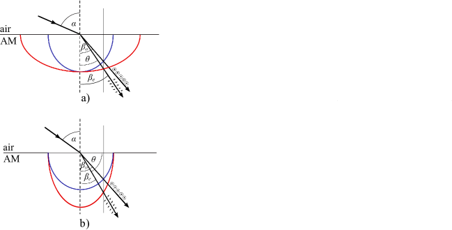
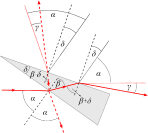
Fig. 2 shows the refraction from an isotropic to an anisotropic medium. In the anisotropic medium the wave vector surfaces are shown for the ordinary and the extraordinary wave for the case of the optic axis being perpendicular (Fig. 2a) and parallel (Fig. 2b) to the interface. The light is incident at an angle , and and are the refraction angles for the wave vector direction of the ordinary and the extraordinary wave, respectively. Assuming that the isotropic medium is air with the refractive index approximately 1, the phase matching boundary condition requires:
| (10) |
where and are the wave vector magnitudes of the ordinary and the extraordinary wave, respectively. Eqs. (10) reduce to
We note that Snell’s law is valid for the direction of the wave vector propagation. However, since it is the direction of the energy propagation (the ray direction) that we actually observe, Snell’s law for the extraordinary wave seems not to be obeyed (see Fig. 1 and draw the directions of energy propagation in Fig. 2). The refraction can be especially striking if the optic axis is at an angle with respect to the interface, since one can observe the ray which refracts to the same side of the normal (not only towards the normal). For the demonstration of this fascinating property of anisotropic materials by using liquid crystals, the reader is referred to Ref. oleg, .
II.2 Optical anisotropy in liquid crystals
Nematic liquid crystals are composed of elongated molecules with orientationally ordered long molecular axes. The average direction of the long molecular axes is called the director. Since all directions of molecular motion in the direction perpendicular to the long molecular axis are equally probable, the system is optically uniaxial with the optic axis along the director. In bulky samples, clusters of oriented molecules are formed, and the director varies in space. In nematic liquid crystals, the orientational correlation length over which one can expect the same orientation of molecules extends to 500 m; therefore, the well-ordered samples have to be thinner than that. fizikatk Within the range of optical frequencies, elongated molecules have greater polarizability along the long molecular axis than perpendicular to it. Thus, when the external electric field is along the director, induced polarization in the liquid crystalline material will be larger than in the case when the electric field is perpendicular to the director. Because of that, the light being polarized perpendicularly to the director ( in the light is perpendicular to the director) will be faster than the light with polarization parallel to the director.
III Experiment
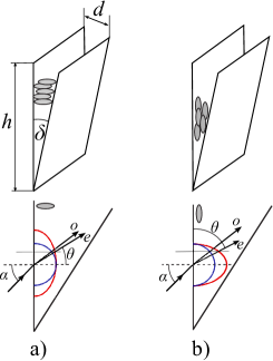
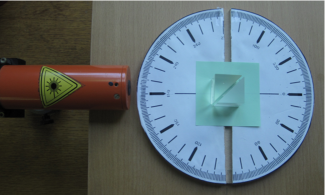
To provide the refraction situations shown in Fig. 2, two wedge cells were designed with different surface treatments in order to achieve different orientations of the director in the cell and thus different orientations of the optic axis with respect to the surface (Fig. 3). The cells were approximately 1 cm long () and half a centimeter wide (Fig. 4a). Usual laser beams are too wide to enable studies of double refraction in cells having parallel surfaces. In thin samples, which guarantee homogeneity of orientation of the long molecular axis (the director gives the direction of the optical axis), the spatial separation of the ordinary and extraordinary beam can be obtained by the prismatic effect. klin ; nclc To prepare a wedge cell, a foil with a thickness was inserted and glued between two pieces of microscope glass in one of the narrower sides, while the other narrow side of the cell was glued together directly, thus forming a wedge. By rubbing the surfaces, the planar cell in which molecules are aligned in the surface plane along the long side of the surface (Fig. 3b) was designed. The elongated molecules align with their long axes along the scratches, and the director is parallel to the rubbing direction. Therefore, the optic axis also coincides with the rubbing direction. To align the molecules perpendicular to the surface (homeotropic cell, Fig. 3a), a polymer coating was applied to the glass. Professional cells usually use carefully engineered coatings, but for simple experiments a satisfactory effect is provided by simply dipping the glass into a detergent or lecithin solution and allowing it to dry. The capillary effect was used to fill the cells with the liquid crystal E18 heated above the transition temperature from the nematic to the isotropic phase. where to buy For E18 at room temperature, the values of the ordinary and extraordinary indices are and . E18
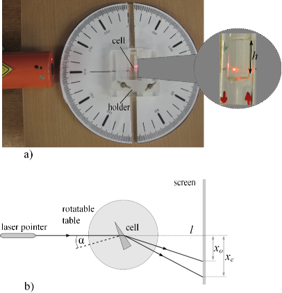
The experimental setup is shown in Fig. 4a. The wedge cell is fixed into a holder and placed on a rotatable table with the longer side parallel to the table surface. A He-Ne laser is used as the source for the unpolarized light. The direction of the incident light is always in the plane perpendicular to the wedge. When the laser beam of unpolarized light is incident on the wedge cell, two bright spots are observed on a distant screen; this is because of the birefringence of the liquid crystal in the wedge cell. The refractive indices are determined by measurements of the relative position of the spots with respect to the position of the direct beam spot, when light does not pass through the cell (Fig. 4b). The position of spots changes as the incident angle of light alters when the table rotates; this enables measurements of the angular dependence of both indices.
Fig. 5 shows the geometry of light propagation through the wedge cell. The angle is the controlled incident angle, and is the refraction angle giving the direction of the wave vector of either the ordinary () or the extraordinary () wave. When exiting the cell the direction of light propagation deviates from the direction of the incident beam by an angle of , which differs for the ordinary and the extraordinary wave and can be calculated from the beam position on the screen and the distance between the cell and the screen as (see Fig. 4b) where, again, one should use for either the ordinary () or the extraordinary () wave.
The refractive indices of the ordinary and the extraordinary wave are obtained by measuring as a function of and knowing the wedge angle of the cell (Fig. 3). Applying Snell’s law at the two interfaces of the wedge cell, we find (see Fig. 5):
| (11) |
where is the refractive index of either the ordinary or the extraordinary wave. In Eq. (11) the upper sign in stands for the beam direction given in Fig. 5 by the red solid line (we shall call this incident angle positive ), and the lower sign for the beam denoted by the red dashed line (negative ). Eq. (11) is an approximation, since the direction of the optic axis in the cell varies slightly because of the wedge. However, since is small, one can assume that the refractive indices of the extraordinary wave at angles and are the same. To confirm this, we measured at incidence angles and found them the same within the experimental error and the width of the beam spots on the screen.
One should also note that, since in the extraordinary wave the energy and the wave vector do not propagate in the same direction in the liquid crystal cell, the extraordinary ray exiting the cell will be displaced from the position shown in Fig. 5, where the wave vector directions are drawn. However, the displacement is of the order of cell thickness and can thus be neglected.
Since the wedge angle and the angle are very small, , and , . By using the sine addition formulae and equating the left parts of Eqs. (11), we find (up to the first order in and ):
| (12) |
from where the refraction angle follows:
| (13) |
With obtained from Eq. (13), the value of the refractive index is found from Eq. (11). Eqs. (11) and (13) are general expressions that can be used to obtain the refractive index when light passes through a thin wedge sample of any, not necessarily birefringent, material and they allow evaluation of the refractive indices of both the ordinary and the extraordinary wave exiting a cell filled by birefringent material.
In the homeotropic cell (Fig. 3 a), the optic axis is perpendicular to the glass plate, and the refraction angle of the extraordinary wave () is equal to the angle between the optic axis and the wave vector, so the refractive index of the extraordinary wave is:
| (14) |
where is calculated from Eq. (13) using the measured value of for the extraordinary wave.
From the measurements performed on the homeotropic cell, the refractive indices of the ordinary and extraordinary wave at angles ranging from to approximately can be obtained.
In the planar cell the optic axis is parallel to the glass, and the refraction angle of the extraordinary wave is related to the angle between the optic axis and the wave vector direction as . The refractive index of the extraordinary wave is therefore given by:
| (15) |
From the measurements in the planar cell, the values are obtained for the refractive index at angles ranging from approximately to . The planar cell can thus be used to study the direction dependency of the refractive index of the extraordinary wave in the region where the difference in the indices of the ordinary and the extraordinary wave is close to its largest value.
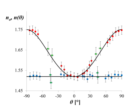
There are a few limitations in the experiment that must be considered. Although the ordinary and extraordinary wave can propagate in any direction, experimentally we are limited with the refraction of the incident light, since the light source is outside the birefringent material. In the presented situation, the wave vector direction of the ordinary wave was theoretically limited (at the incident angle ) to at and for the extraordinary wave to at . The cell size and the cell holder additionally limit the incident angle . Fig. 6 shows the combined results of the angular dependence of the refractive indices of the ordinary and the extraordinary wave measured in the planar and the homeotropic cell. The theoretical dependence was calculated from Eq. (9) using the known values of and .
From Fig. 6 it can clearly be seen that with such a simple experiment we were not able to measure the values of the refractive indices for directions of propagation close to . To measure the refractive indices for these directions as well, one should use an old experimental trick: phase matching with the help of an additional material. trik In order to enter the liquid crystal under a general angle, one should prevent refraction between two materials that have a large difference in refractive indices. Therefore, the light should pass a surface where refractive indices of materials on both sides of the surface are similar.
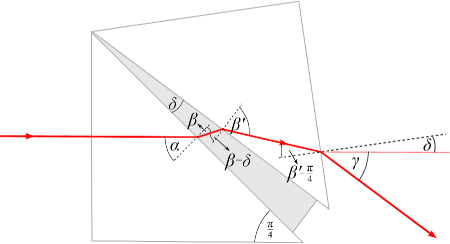
To achieve such conditions, the wedge cell is sandwiched between two glass prisms (refractive index = 1.50) with an apex angle of (Fig. 7). To prevent any possibility of a tiny air interface between the prism and the wedge cell, the contact areas are covered by glycerol, which has a refractive index similar to the refractive indices of glass and liquid crystal. glycerol If the incident angle on the prism surface is zero, the beam does not refract and the incident angle to the liquid crystal in the wedge is (Fig. 8). Since the refractive indices of glass and liquid crystal are similar, the angle of refraction does not differ much from the incident angle, and in the liquid crystal light propagates in a direction close to . The prism at the other side of the cell provides a change in light direction that is opposite to the first one. Without the wedge cell, the light beam should be straight. Therefore the positions of the two light spots again allow simultaneous measurement of both refractive indices.
Let us follow the light beam through the sandwich and calculate the refractive indices (Fig. 8). If the glycerol film is of uniform thickness, it does not influence the analysis of the refractive indices. The first relevant interface is thus the glass - liquid crystal interface. The incident angle is , and the beam refracts only slightly ( is close to ) because the refractive indices of liquid crystal are close to 1.5. At the liquid crystal - glass interface, the incident angle changes, owing to the wedge angle , to , as in Fig. 8, or to if the sandwich is rotated clockwise. Therefore, Snell’s law gives:
| (16) |
where is the refraction angle from the liquid crystal to the glass (see Fig. 8). The last refraction occurs at the glass - air interface. The incident angle is equal to , as in Fig. 8, or if the sandwich is rotated 90 degrees clockwise, as in Fig. 7. One can write Snell’s law as
| (17) |
The angle between the optic axis and the wave vector direction of the extraordinary/ordinary wave is equal to in the homeotropic cell and in the planar cell (see Fig. 3).
As explained above, the sandwiched cells provide extra measurements of refractive indices at angles close to . Since we have two cells with different alignments of molecules and two different orientations of sandwich as in Figs. 7 and 8, the refractive indices in four different directions of light propagation in the cell with respect to the optical axis can be measured. These measurements are shown as green diamonds in Fig. 6. One can clearly see that the accuracy of the refractive index measurement when the wedge cell is fixed between the prisms is much lower than when the prisms are absent. The reason is the glycerol, because it forms a slight wedge as well, which could not be precisely controlled. In most cases, the wedge of the glycerol has the same orientation as the wedge of the liquid crystalline cell, a fact which results in larger values for refractive indices. Less frequently, the glycerol wedge is in the opposite direction, which leads to lower values for the refractive index. The effect was verified in the absence of the liquid crystal. Nevertheless, the experiment nicely shows that values of the refractive indices at between and are consistent with the calculated direction dependence of the refractive index of the extraordinary wave in the uniaxial liquid crystal.
IV Conclusion
Students are confronted by the difficult concept of birefringence during physics lessons at university. We have shown that the concept can be fully demonstrated by using nematic liquid crystalline wedge cells with different orientation of molecules. Most important, the experiment, the setup of which consists of a laser, rotatable table, two different wedge cells, two prisms with an apex angle of and a drop of glycerol, enables quantitative measurements of the angular dependence of the refractive index of the extraordinary wave for the whole range of propagation directions. The homeotropic cell permits the demonstration of the direction dependency of the refractive index of the extraordinary wave, as well as its measurement, when its value is close to the value of the ordinary refractive index. The planar cell can be used for quantitative measurement of the refractive index direction dependency close to its largest value. By using additional glass prisms to form a sandwich of prisms and the wedge cell, one can study the angular dependency of the refractive indices in a range of directions that cannot be attained with a simple setup.
Acknowledgements.
The authors are grateful to Miha Škarabot for producing the wedge cells, to Martina Šubic for the control set of measurements and to Igor Muševič for pointing out the paper by Barnik et al. trik This work was supported by the project J5-4002 financed by the Slovenian Research Agency (ARRS).References
- (1) P. Oswald, and P. Pieranski, Nematic and Cholesteric Liquid Crystals: Concepts and Physical Properties, (Taylor and Francis, New York, 2005).
- (2) M. Čepič, “Knitted patterns as a model for anisotropy,” Phys. Educ. 47, 456-61, (2012).
- (3) T. M. Ciferno, R. J. Ondris-Crawford, and G. P. Crawford, “Inexpensive electrooptic experiments on liquid crystal displays,” Phys. Teach. 33(2), 104-10 (1995).
- (4) J. Pavlin, K. Susman, S. Ziherl, N. Vaupotič, and M. Čepič, “How to teach liquid crystals,” Mol. Cryst. Liq. Cryst. 547, 255-61 (2011).
- (5) P. Pieranski, “Classroom experiments with chiral liquid crystals,” in Chirality in Liquid Crystals, edited by H. Kitzerow and Ch. Bahr, (Springer, New York, 2001).
- (6) E. Hecht, Optics, 3rd ed. (Addison Wesley Longman, Reading, 1998).
- (7) L. Verbit, “Liquid Crystals: Synthesis and Properties,” J. Chem. Educ., 49(1), 36-39 (1972).
- (8) J. J. Wright, “Optics Experiments with Nematic Liquid Crystals,” Am. J. Phys., 41 2), 270-72 (1973).
- (9) C. A. Liberko, and J. Shearer, “Preparation of a surface-oriented liquid crystal - An experiment for the undergraduate organic chemistry laboratory,” J. Chem. Educ. 77(9), 1204-05 (2000).
- (10) J. Pavlin, N. Vaupotič, S. A. Glažar, M. Čepič, and I. Devetak, “Slovenian pre-service teachers’ conceptions about liquid crystals,” Eurasia, 7(3), 173-80 (2011).
- (11) For a quick overview, we suggest the concise treatment in Ref. Rogalski, , but, of course, any book on optics or modern optics (as Refs. optics, ; Guenther, ; Fowles, ; Brooker, ) will also have a thorough treatment of light propagation in anisotropic media.
- (12) M. S. Rogalski and S. B. Palmer, Advanced University Physics, 2nd ed. (Chapman & Hall/CRC Taylor, Francis Group, Boca Raton, 2006).
- (13) M. Born and E. Wolf, Principles of Optics, 7th (expanded) ed. (Cambridge University Press, Cambridge, 1999).
- (14) R. Guenther, Modern Optics (John Wiley & Sons, New York, 1990).
- (15) G. R. Fowles, Modern Optics, 2nd ed. (Dover Publications, New York, 1989).
- (16) G. Brooker, Modern Classical Optics (Oxford University Press, Oxford, 2011).
- (17) O. P. Pishnyak, and O. D. Lavrentovich, “Electrically controlled negative refraction in a nematic liquid crystal,” Appl. Phys. Lett. 89, 251103 (2006).
- (18) P. G. de Gennes, and J. Prost, The Physics of Liquid Crystals, 2nd ed. (Oxford Science Publications, Oxford, 1995).
- (19) D. K. Shenoy, “Measurements of Liquid Crystal Refractive Indices,” Am. J. Phys. 62, 858-59 (1994).
- (20) Nematic liquid crystals with appropriate properties are commercially available from several companies like Merck, Sigma Aldrich or Nematel. Different commercial mixtures are available which are in the liquid crystalline state around the room temperature. The measurements can be done with any nematic liquid crystals that have the nematic phase at the room temperature and have high birefringence. Instead, we can also use the liquid crystal MBBA which is quite easy to synthesize in the school lab. We have used E18, which was available in the lab, however, this mixture cannot be bought any more.
- (21) BDH Catalog, BDH Chemical Ltd., Poole BH 12 4NN, England 1978, p. 21.
- (22) Refractive index of glycerol, http://refractiveindex.info/.
- (23) M. I. Barnik, L. M. Blinov, A. M. Dorozhkin, and N. M. Shtykov, “Generation of the second optical harmonic induced by an electric field in nematic and smectic liquid crystals,” Sov. Phys. JETP 54(5), 935-38 (1981).