Vortex lock-in transition coinciding with the 3D to 2D crossover in YBa2Cu3O7
Abstract
A vortex lock-in transition was directly detected by torque magnetometry in an overdoped YBa2Cu3O7 single crystal of low anisotropy (). The locked-in state was observed below the 3D to 2D crossover temperature , independently of extrinsic pinning effects thanks to a high quality clean crystal and the use of a vortex shaking technique. The shape of the torque signal as a function of the angle between the applied magnetic field and the crystallographic -axis is in very good agreement with the model developped by Feinberg and Ettouhami [Int. J. Mod. Phys. B 7, 2085 (1993)] for quasi-2D superconductors, despite the low anisotropy of the material.
pacs:
74.20.De; 74.25.Ha; 74.72.-hI Introduction
Dimensionality is essential to understand the behavior of vortices in layered cuprate superconductors. A three-dimensional (3D) to two-dimensional (2D) crossover takes place when the superconducting coherence length along the -axis becomes smaller than the distance between the planes supporting superconductivity.Blatter et al. (1994) Since decreases with decreasing temperature, it will in many cases become smaller than below some temperature. The Lawrence-Donniach model should then be used to describe superconductivity.Lawrence and Doniach (1971) The temperature at which this crossover happens is such that , where and is the superconductor critical temperature. For YBa2Cu3O7, taking nm and nm, one gets K.
In the 2D regime, when the applied magnetic field direction is nearly parallel to the -plane, a lock-in transition may take place.Feinberg and Villard (1990) In this case, the vortex cores are confined between the superconducting layers, even though the field is not aligned with these layers. This minimizes condensation energy at the cost of magnetic energy coming from the misalignement of vortices and field, since the cores do not cross the layers anymore. This is also known as intrinsic pinning, since it locks the vortices independently of (extrinsic) impurities.
In high anisotropy materials lock-in studies,Steinmeyer et al. (1994); Janossy et al. (1995); Okram et al. (2001); Zehetmayer et al. (2005) the 2D character is so strong that the lock-in is present almost up to . However, the vicinity of the superconducting transition makes it difficult to observe the lock-in onset. Low anisotropy cuprates like YBa2Cu3O7 or YBa2Cu4O8 are more suited for this purpose. The lock-in was observed in YBa2Cu3O7 by torque magnetometry,Farrell et al. (1990); Kortyka et al. (2010) bulk resistivity measurements,Kwok et al. (1991); Gordeev et al. (2000) and AC transport in thin films.Doyle et al. (1993) The lock-in was also observed in various other layered superconductors.Vermeer et al. (1991); Mansky et al. (1993); Koleśnik et al. (1996); Bugoslavsky et al. (1997); Avila et al. (2001); Khene (2004); Kohout et al. (2007a) It may be difficult to distinguish between pinning and lock-in effects (see for example Ref. Kortyka et al., 2010). Besides, a large irreversibility due to extrinsic pinning effects may hide the appearance of the lock-in transition: in Ref. Zech et al., 1996, the lock-in transition is identified much below the 3D to 2D crossover temperature . In this work, the appearance of the vortex lock-in is clearly observed by torque magnetometry at in a clean overdoped YBa2Cu3O7 single crystal.
A review of lock-in theoretical models is given in Ref. Blatter et al., 1994 (p. 1286). The most relevant models for this work are presented in Refs. Bulaevskii, 1991; Feinberg and Ettouhami, 1993. The lock-in angle corresponds to the angle between the applied magnetic field and the crystallographic -axis at which the lock-in appears. This angle is the crucial parameter turning the lock-in on and off. Previous experiments on various cuprate superconductors were in agreement with the theory whenever data accuracy made the comparison possible, but the data in the case of YBa2Cu3O7 were rather sparse. In this work, we present a detailed study of the field and temperature dependence of the lock-in effect in a low anisotropy cuprate superconductor. We note a very good qualitative agreement with the behavior described in Ref. Feinberg and Ettouhami, 1993, although the field dependence of the lock-in angle seems unconventionnal. The field is chosen in the London domain , where and are the lower and upper critical fields. This excludes the interference of other phenomena like vortex lattice melting or glass behavior. The temperature range has a lower bound of 60 K, because irreversibility renders the data unreliable below this temperature; the torque ceases to conform to the model described in Ref. Feinberg and Ettouhami, 1993.
II Torque measurements
The growth procedure and detwinning of the high-quality superconducting YBa2Cu3O7 single crystal used in this experiment is described in Ref. Erb et al., 1999. The dimensions of the platelet crystal are 13016050 m3, and K. Magnetic torque investigations were carried out using a home-made magnetic torque sensor.Kohout et al. (2007b) The sample is attached to a platform hanging on piezoresistive legs. When a magnetic field is applied on an anisotropic superconductor, the misalignement between field and diamagnetic moment results in a torque. This bends the legs, thus giving rise to a measureable electric signal proportional to the magnetic torque. For a uniaxial superconductor, the angular dependence of the magnetic torque (where is the sample magnetic moment) in the London approximation () can be written asKogan (1988)
| (1) |
where is the angle between the applied magnetic field and the crystallographic -axis, is the angular scaling function, is the -axis upper critical field, and is a dimensionless parameter of the order of unity. The anisotropy parameter / is the ratio of the out-of-plane and in-plane magnetic penetration depths; ( is the sample volume, is the flux quantum) is independent of angle. This model is 3-dimensionnal.
A typical torque signal of YBa2Cu3O7 measured in a magnetic field of 1.4 T at 70 K is shown in Fig. 1. During a torque measurement, the field direction is swept clockwise (CW) from the -axis (0∘) through the -plane (90∘) and the opposite direction of the -axis (180∘), then swept back counter-clockwise (CCW), as shown in the inset of Fig. 1. The CW and CCW branches of the raw unaveraged torque signal overlap when the torque is reversible. The torque signal is antisymetric with regards to the -plane, so the rest of the data are shown only in the angle range 0∘ to 90∘ for clarity.
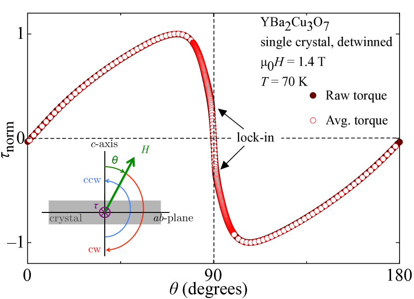
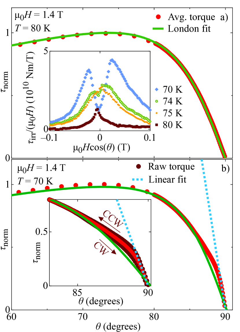
Figure 2 shows a torque measurement evidencing the lock-in effect; a deviation from Eq. (1) can be seen at low temperatures close to the -plane for . This corresponds to a staircase configurationFeinberg and Ettouhami (1993) of the vortices. The order parameter inside a vortex core is not suppressed between the layers, because the circulating currents are Josephson currents and not superconducting currents. The order parameter is only suppressed within the superconducting layers. The vortex consists of 2D cores in the layers, linked by Josephson cores between the layers. When the vortices are tilted enough that the Josephson coherence length is smaller than the distance between two consecutive vortex cores, the vortex line takes a staircase shape. The physics stays 3D on large scales, but the free energy deviates from the 3D London model.Feinberg (1992) For the lock-in starts: the torque becomes linear and changes slope. This shape of the averaged angular dependent torque is identical to the prediction of the model presented in Ref. Feinberg and Ettouhami, 1993 for quasi-2D superconductors. This similarity is striking, as the anisotropy of our YBa2Cu3O7 crystal is around 7,Bosma et al. (2011) which would not qualify as quasi-2D. The models presented in Ref. Feinberg and Ettouhami, 1993 relate to anisotropies around 50, as expected in La2-xSrxCuO4 for example.
The torque data exhibits an angular irreversibility between the clockwise (CW) and counter-clockwise (CCW) branches. Such irreversible signals are usually due to vortex pinning. In this work, the so-called vortex-shaking techniqueWillemin et al. (1998) was applied to reduce irreversibility. This was done by applying a small AC field orthogonal to the main field in order to enhance the vortex relaxation towards thermodynamic equilibrium. The irreversible part of the torque is shown in the inset of Fig. 2a. The shape of changes when the lock-in appears. The double peak shape of is characteristicZech et al. (1996) of the lock-in state. This confirms the lock-in transition temperature around 75 K. The small residual irreversibility as seen on the averaged torque could not be hiding a small higher temperature lock-in signal, because lock-in shows up as well in the shape of . Besides, the difference between the London fit and the averaged torque is too large to be an artifact of irreversibility (Fig. 2b inset).
Figure 3 shows the angular torque at various temperatures and fields. A small residual irreversibility is visible close to the -plane, at the same angles where lock-in takes place. This irreversibility decreases with increasing temperature, as expected for vortex pinning. It also decreases with decreasing field, as observed in YBa2Cu4O8,Zech et al. (1996) but contrary to what was observed in YBa2Cu3O7.Farrell et al. (1990) The dependence of the pinning forces on field depends on the crystal quality and field range of the experiment, which may explain this different field behavior. In a clean crystal like the one used in this work, the only source of pinning is the layered structure; the appearance of irreversibility is thus a supplementary indication of the onset of lock-in.
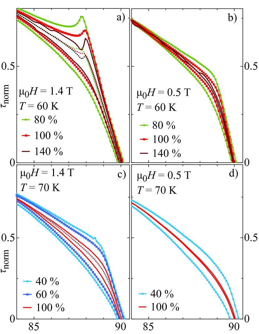
In order to investigate the effect of vortex shaking on the lock-in phenomenon, we studied different shaking field amplitudes at various static fields and temperatures. At low temperature and high fields (Fig. 4a), the shaking is not sufficient to ensure reliable measurements, since the averaged data depend on the shaking power. The linear lock-in zone is reduced by increasing shaking power. The shaking efficiency limit is reached when a small peak appears at the limit of the lock-in domain. The peak feature in the CCW branch of the torque is characteristic of lock-in observed in conjunction with extrinsic pinning.Kortyka et al. (2010) This usually masks the lock-in effect in lower quality crystals. In this work the peak appears only if the extrinsic pinning becomes too large to be suppressed at low temperatures. At low temperature and low field (Fig. 4b), and high temperature and high field (Fig. 4c), the shaking power is sufficient to get stable data. All the averaged torque signals for the various shaking powers are the same. At low fields and high temperatures (Fig. 4d), the shaking is even sufficient to get fully reversible data. We consider that the lock-in properties are reliably measured if increasing the shaking power does not change the shape of the averaged torque.
III Discussion
The analysis was done on the average of the CW and CCW data, since the deviation of the averaged data from the London model is larger than the irreversibility, as also reported in Ref. Farrell et al., 1990. The lock-in angle is often viewed as the angle at which the perpendicular component of the field goes below the lower critical field along the -axis. Field penetration across the layers is then impossible, effectively locking the vortices in the -planes. In this model, the lock-in angle should be such that equals , so should decrease with increasing field. This evolution was observed in high anisotropy cuprates,Zehetmayer et al. (2005) and a similar dependence was derived for YBa2Cu3O7,Feinberg and Villard (1990); Bulaevskii (1991) although not confirmed by experiments in this material. However, Ref. Vulcanescu et al., 1994 reports in La2-xSrxCuO4 ( = 0.075) a transverse lock-in field which is different from . It is thus possible that this simple picture holds only for high-anisotropy compounds, and that the lock-in angle is not necessarily inversely proportionnal to the field.
The vortices direction is along the magnetic induction ; is therefore aligned with the planes in the lock-in state (but is not). Since and is small compared to , can be approximated as the parallel component of : . In that case, the torque becomes:
| (2) |
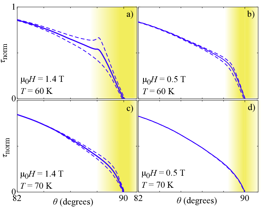
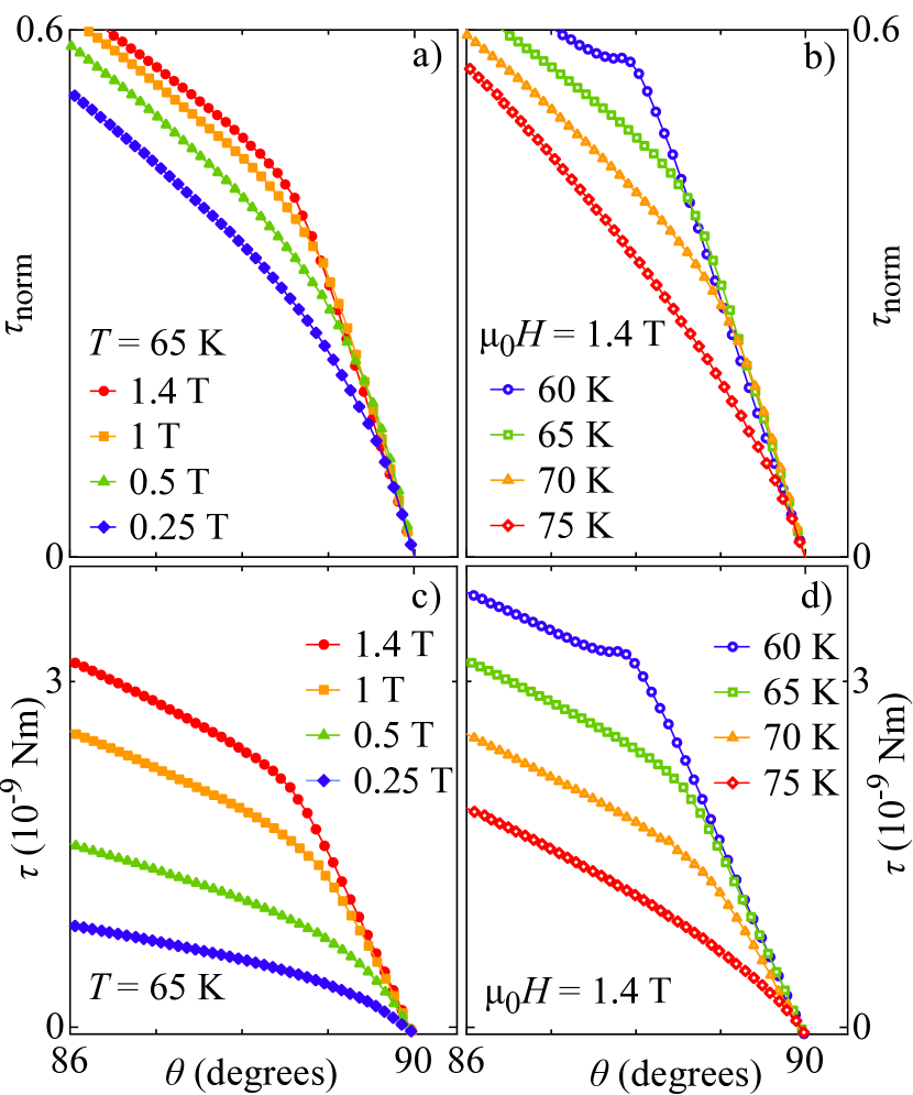
Figure 5 shows the lock-in transition at various fields and temperatures. If we define the lock-in angle as the angle where the torque slope changes (moves away from the linear region), increases at low temperatures, but also at high fields. However, becomes more difficult to identify at higher temperatures and lower fields. It is possible that the observed unconventional increase of at high fields is biased; since the transition is smoother at low fields, the field dependence of might be drowned in the large transition. can also be defined as the point at which the torque is no longer independent of temperature, and therefore not following Eq. (2). In that case, we can reliably identify the temperature dependence of from measurements at constant field. Figure 5c and d show the non normalized torque in the lock-in region; it appears that even though all curves merge around the -plane, the torque slope depends slightly on temperature, contrary to the prediction of Eq. (2). At low temperatures, the transition sharpness increases and the slope depends more weakly on temperature. Since the lock-in transition is not sharp at higher temperatures, the curvature of the torque that accompanies this transition may skew the linear region and change the slope dependence given by Eq. (2).
IV Conclusion
A lock-in transition was observed in a clean detwinned YBa2Cu3O7 single crystal at the 2D to 3D crossover temperature. Although the angular torque signal matches theoretical shapes, it seems difficult to qualitatively confirm a simple model of the lock-in. The lock-in angle domain decreases with increasing temperature, as expected for vortex pinning. Surprisingly, this domain also seems to increase with field in the studied field range (0 to 1.4 T), although this dependence may be an artifact of a broad lock-in transition. This unconventional behavior might be related to the low anisotropy of the compound, which prevents it from having a strong 2D behavior, even at low temperatures.
V Acknowledgements
Helpful discussions with D. Feinberg and V. B. Geshkenbein are gratefully acknowledged. This work was supported by the Swiss National Science Foundation.
References
- Blatter et al. (1994) G. Blatter, M. V. Feigel’man, V. B. Geshkenbein, A. I. Larkin, and V. M. Vinokur, Rev. Mod. Phys. 66, 1125 (1994).
- Lawrence and Doniach (1971) W. E. Lawrence and S. Doniach, Theory of layer structure superconductors (1971) p. 361.
- Feinberg and Villard (1990) D. Feinberg and C. Villard, Phys. Rev. Lett. 65, 919 (1990).
- Steinmeyer et al. (1994) F. Steinmeyer, R. Kleiner, P. Müller, H. Müller, and K. Winzer, Europhys. Lett. 25, 459 (1994).
- Janossy et al. (1995) B. Janossy, A. de Graaf, P. H. Kes, V. N. Kopylov, and T. G. Togonidze, Physica C 246, 277 (1995).
- Okram et al. (2001) G. S. Okram, H. Aoki, M. Xu, and D. G. Hinks, Physica C 355, 65 (2001).
- Zehetmayer et al. (2005) M. Zehetmayer, M. Eisterer, S. Sponar, H. Weber, A. Wisniewski, R. Puzniak, P. Panta, S. Kazakov, and J. Karpinski, Physica C 418, 73 (2005).
- Farrell et al. (1990) D. E. Farrell, J. P. Rice, D. M. Ginsberg, and J. Z. Liu, Phys. Rev. Lett. 64, 1573 (1990).
- Kortyka et al. (2010) A. Kortyka, R. Puzniak, A. Wisniewski, M. Zehetmayer, H. W. Weber, Y. Q. Cai, and X. Yao, Supercond. Sci. Tech. 23, 065001 (2010).
- Kwok et al. (1991) W. K. Kwok, U. Welp, V. M. Vinokur, S. Fleshler, J. Downey, and G. W. Crabtree, Phys. Rev. Lett. 67, 390 (1991).
- Gordeev et al. (2000) S. N. Gordeev, A. A. Zhukov, P. A. J. de Groot, A. G. M. Jansen, R. Gagnon, and L. Taillefer, Phys. Rev. Lett. 85, 4594 (2000).
- Doyle et al. (1993) R. A. Doyle, A. M. Campbell, and R. E. Somekh, Phys. Rev. Lett. 71, 4241 (1993).
- Vermeer et al. (1991) A. Vermeer, D. de Groot, N. Koeman, R. Griessen, and C. van Haesendonck, Physica C 185, 2345 (1991).
- Mansky et al. (1993) P. A. Mansky, P. M. Chaikin, and R. C. Haddon, Phys. Rev. Lett. 70, 1323 (1993).
- Koleśnik et al. (1996) S. Koleśnik, T. Skośkiewicz, J. Igalson, and Z. Tarnawski, Phys. Rev. B 54, 13319 (1996).
- Bugoslavsky et al. (1997) Y. V. Bugoslavsky, A. A. Zhukov, G. K. Perkins, A. D. Caplin, H. Kojima, and I. Tanaka, Phys. Rev. B 56, 5610 (1997).
- Avila et al. (2001) M. A. Avila, L. Civale, A. V. Silhanek, R. A. Ribeiro, O. F. de Lima, and H. Lanza, Phys. Rev. B 64, 144502 (2001).
- Khene (2004) S. Khene, Physica B 349, 227 (2004).
- Kohout et al. (2007a) S. Kohout, T. Schneider, J. Roos, H. Keller, T. Sasagawa, and H. Takagi, Phys. Rev. B 76, 064513 (2007a).
- Zech et al. (1996) D. Zech, C. Rossel, L. Lesne, H. Keller, S. L. Lee, and J. Karpinski, Phys. Rev. B 54, 12535 (1996).
- Bulaevskii (1991) L. N. Bulaevskii, Phys. Rev. B 44, 910 (1991).
- Feinberg and Ettouhami (1993) D. Feinberg and A. M. Ettouhami, Int. J. Mod. Phys. B 7, 2085 (1993).
- Erb et al. (1999) A. Erb, A. A. Manuel, M. Dhalle, F. Marti, J. Y. Genoud, B. Revaz, A. Junod, D. Vasumathi, S. Ishibashi, A. Shukla, E. Walker, Ø. Fischer, R. Flükiger, R. Pozzi, M. Mali, and D. Brinkmann, Solid State Commun. 112, 245 (1999).
- Kohout et al. (2007b) S. Kohout, J. Roos, and H. Keller, Rev. Sci. Instrum. 78, 013903 (2007b).
- Kogan (1988) V. G. Kogan, Phys. Rev. B 38, 7049 (1988).
- Feinberg (1992) D. Feinberg, Physica C 194, 126 (1992).
- Bosma et al. (2011) S. Bosma, S. Weyeneth, R. Puzniak, A. Erb, A. Schilling, and H. Keller, Phys. Rev. B 84, 024514 (2011).
- Willemin et al. (1998) M. Willemin, C. Rossel, J. Hofer, H. Keller, A. Erb, and E. Walker, Phys. Rev. B 58, R5940 (1998).
- Vulcanescu et al. (1994) V. Vulcanescu, G. Collin, H. Kojima, I. Tanaka, and L. Fruchter, Phys. Rev. B 50, 4139 (1994).