Ion energy distribution functions behind the sheaths of magnetized and non magnetized radio frequency discharges
Abstract
The effect of a magnetic field on the characteristics of capacitively coupled radio frequency discharges is investigated and found to be substantial. A one-dimensional particle-in-cell simulation shows that geometrically symmetric discharges can be asymmetrized by applying a spatially inhomogeneous magnetic field. This effect is similar to the recently discovered electrical asymmetry effect. Both effects act independently, they can work in the same direction or compensate each other. Also the ion energy distribution functions at the electrodes are strongly affected by the magnetic field, although only indirectly. The field influences not the dynamics of the sheath itself but rather its operating conditions, i.e., the ion flux through it and voltage drop across it. To support this interpretation, the particle-in-cell results are compared with the outcome of the recently proposed ensemble-in-spacetime algorithm. Although that scheme resolves only the sheath and neglects magnetization, it is able to reproduce the ion energy distribution functions with very good accuracy, regardless of whether the discharge is magnetized or not.
I Introduction
In the past three decades plasma processing such as surface activation, deposition, or etching has become of great importance for a large number of technological applications. With the goal of optimizing plasma processes, several types of plasma sources have been successfully introduced and studied, e.g., hybrid plasma sources, capacitively coupled radio frequency discharges (CCRFDs) driven by more than one frequencies, or magnetized CCRFDs which are used for magnetically enhanced reactive ion etching (MERIE). It has been recently shown that dual frequency CCRFDs which exploit the electrical asymmetry effect (EAE) are most suitable for a separate control of the ion flux and energy at substrates or electrodes heil2008 ; czarnetzki2009 . It is possible to control the ion energy distribution function over a wide range of parameters. In fact, this is one of the main goals in the context of plasma processing kawamura1999 ; mussenbrock2012 . By utilizing the EAE it is even possible to invert the electrode functionality, i.e., to change the DC self bias voltage from a large negative value to a large positive value even for geometrically symmetric CCRFDs with the driven electrode area equal to the grounded area. It has been further shown that geometrically asymmetric CCRFDs (small driven electrode and large grounded area, or vice versa), which produce a natural DC self bias voltage, can be completely symmetrized, in the sense that the natural DC self bias voltage can be completely compensated schulze2011 ; schuengel2012 .
In this work we study the effect of an externally imposed static magnetic field in combination with the EAE on the characteristics of dual frequency CCRFDs. We focus on the sheath dynamics and the IEDFs at the electrodes. Similar to the MERIE concept where usually a static and spatially inhomogeneous magnetic field is applied cheng1989 ; lieberman1991 ; graves1994 ; rauf2003 ; kushner2003 ; oster2004 , we investigate the effect of a spatially inhomogeneous magnetic field on the IEDF. It will be shown, that the applied magnetic field is able to (over-)compensate or even to amplify the EAE.
The manuscript is organized as follows. After a short introduction of the discharge configuration and the operation regime, a brief review of the employed numerical schemes, namely a one-dimensional Particle-in-Cell algorithm using Monte-Carlo collisions (PIC) and the Ensemble-in-Space time scheme (EST), is presented shihab2012 . We discuss simulation results for both the magnetized and the non-magnetized case, focussing on the sheath dynamics and the IEDFs. We conclude that the IEDFs are completely controlled by the sheath dynamics, even in magnetized CCRFDs. Having argued that, we show that EST can be used as an efficient postprocessing tool to obtain the IEDFs behind the sheaths in non-magnetized and magnetized discharges prenzel2012 .
II Discharge Setup
Magnetized discharges used for processes such as MERIE employ a static and usually inhomogeneous magnetic field to obtain a high electron density at very low gas pressures (Pascal or sub-Pascal range). The spatial dimensions of such discharges are typically a few centimeters, and the magnetic field strength can vary up to tens of mT. Under such conditions the electrons are magnetized and their effective mobility is reduced; as will be discussed, later this leads to a larger voltage drop across the plasma bulk and thus to a larger plasma density and corresponding ion flux. The ions, in contrast, are not magnetized (particularly not in the sheath), as their Larmor radius is large compared with the typical length scales of the system. For instance, the ratio of and the average sheath width is . Here and are the ion plasma frequency and the ion cyclotron frequency, respectively.
In this work we investigate a magnetized Argon discharge at Pa. The chamber configuration is depicted in figure 1; it is a flat, geometrically symmetric cylinder of height = 5 cm. The chamber walls are dielectric, except for the two opposite electrodes of area 10 m2 (which is small compared to the diameter of the chamber). The geometric symmetry of the chamber is broken by an external magnetic field of “half-magnetron” shape which is applied near the left electrode (cf. the magnetic field configuration depicted in figure 1), and by an electrically asymmetric discharge voltage applied to the left electrode via a blocking capacitor of nF. We assume the following explicit form, where the relative phase – the control parameter for the Electrical Asymmetry Effect (EAE) – varies between and :
| (1) |
This discharge is simulated under the assumption of a one-dimensional geometry. Clearly, this assumption is rather drastic and neglects the inherent inhomogeneity of the magnetic field and many phenomena related to it (e.g., particle drifts and magnetic mirror effects). However, for the purpose of calculating IEDFs behind the sheaths the assumption can be justified, at least for the small corridor (indicated by the dashed lines) where the magnetic field is approximately parallel to the electrodes.
In a magnetized discharge, current flow along the field lines is not inhibited. However, in our case, all field lines end at dielectric sections of the wall; this suppresses the RF current and turns the field lines into equipotential lines. In other words, the current can only flow into the electrodes, roughly along the dashed corridor. In our one-dimensional model we assume that the magnetic field is given as follows:
| (2) |
where the maximum magnetic field amplitude is = 6 mT and the decay length is = 5 mm. The profile of within the corridor is shown in figure 2.
Preliminary results of a self-consistent two-dimensional PIC simulation of the discussed discharge configuration indicate that the presented reasoning is essentially valid: a one-dimensional approximation can capture the essential physics relevant to our topic.
III Numerical Analysis
To analyze the magnetized (and non-magnetized) CCRFD described above, we employ two conceptually different kinetic approaches. The first is the explicit electrostatic 1d3v PIC code yapic which has been benchmarked against a number of different PIC codes turner2013 . Within a single PIC cycle the Poisson solver, the particle pusher and the Monte-Carlo collision module are successively iterated until convergence of the overall simulation is achieved. To couple the different modules, a first order field interpolation and charge assignment is performed. (See e.g., birdsall1991 ). Since the discharge is assumed to be magnetized both particle species, electrons and ions, are moved according to the full Lorentz force law , although the ions are mainly non-magnetized due to their large mass). We apply an explicit push scheme based on Boris’ approach boris1970 . Collisions of electrons and ions with the fixed background gas are performed in the frame of a slightly modified null-collisions method reported by Mertmann et al. mertmann2011 , with respect to the classical method proposed by Skullerud skullerud1968 . Since Argon is used as the background gas the collision processes include elastic scattering of both electrons and ions, ionization and excitation due to electron collisions, and backward scattering (i.e., charge exchange collisions) of ions. Cross-section data are taken from Phelps et al. and the LXCat Database phelps1994 ; lxcat2012 .
The second approach which is used in the end of this paper relies on the Ensemble-in-Space time (EST) scheme which resolves only the sheath, unlike PIC which treats the entire discharge. EST is an iterative algorithm based on the solution of a set of kinetic equations for the ions, Boltzmann’s relation for the electrons, and Poisson’s equation for the electric field. Similar to PIC, EST employs the null-collision method to account for elastic and charge exchange collisions of ions, but does not take into account ionization and excitation processes. EST is fed by two input parameters: the first is the ion flux through the sheath. The second is the sheath voltage which can have an arbitrary but periodic waveform. Because of its efficient convergence behavior, EST allows for fast and kinetically self-consistent simulations of sheaths of CCRFDs. More details concerning the mathematical description and the validation of the model can be found in shihab2012 .
In order to calculate the sheath voltage as one input parameter for EST from the PIC simulation results, we define the time-dependent sheath width using
| (3) |
This definition is proposed by Brinkmann brinkmann2007 and can be substituted by other definitions of the sheath edge. The sheath voltage is then the potential difference between the potential at the position and the electrode potential. The ion flux as the second input parameter is taken from the PIC simulation somewhere in the quasineutral zone near the sheaths. It is clear that the input parameters for EST can also be obtained from other plasma simulation approaches, e.g., fluid simulations or global plasma models. It is important to note that EST does not include any magnetic field forces.
IV Results and Discussion
IV.1 Magnetically induced asymmetry of CCRFD
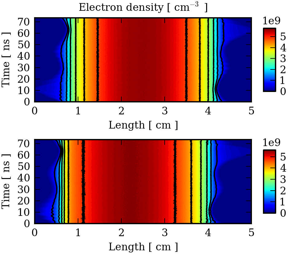
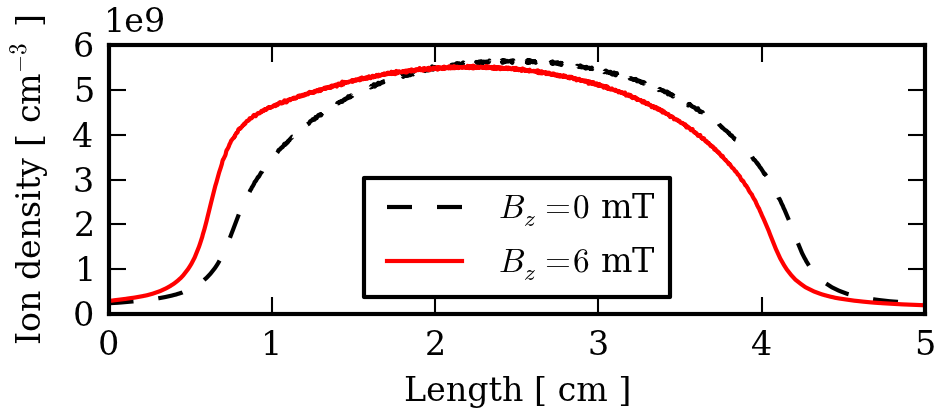
We start our analysis by comparing two different discharge scenarios using PIC simulations. Case I is without and case II is with an applied static magnetic field at the left electrode. The simulation parameters are specified in section II. The relative phase between the two consecutive harmonics of the driving voltage is set to . Figure 3 shows the spacetime dynamics of the electron densities for the two different cases. For case I we obtain, as expected, a symmetric density profile and symmetric sheath dynamics. In contrast, for case II the discharge shows a significant asymmetry due to the applied magnetic field. This asymmetry can also be observed in figure 4 where the time-averaged ion density profiles are shown. It is clearly visible that the maximum is shifted and the slope is steeper towards the magnetized region in front of the left electrode.
There are two competing mechanisms governing the electrical conductivity in the magnetized region. At first sight electron transport is suppressed by the magnetic field. This leads to a decrease of the conductivity. On the other hand, due to the confinement of the electrons the plasma heating and thus the ionization processes become more efficient. As a result, the plasma density slightly increases locally, followed by corresponding enhancement in the conductivity. The cumulative effect of these two different mechanisms is that locally the net conductivity decreases, while the plasma density increases.
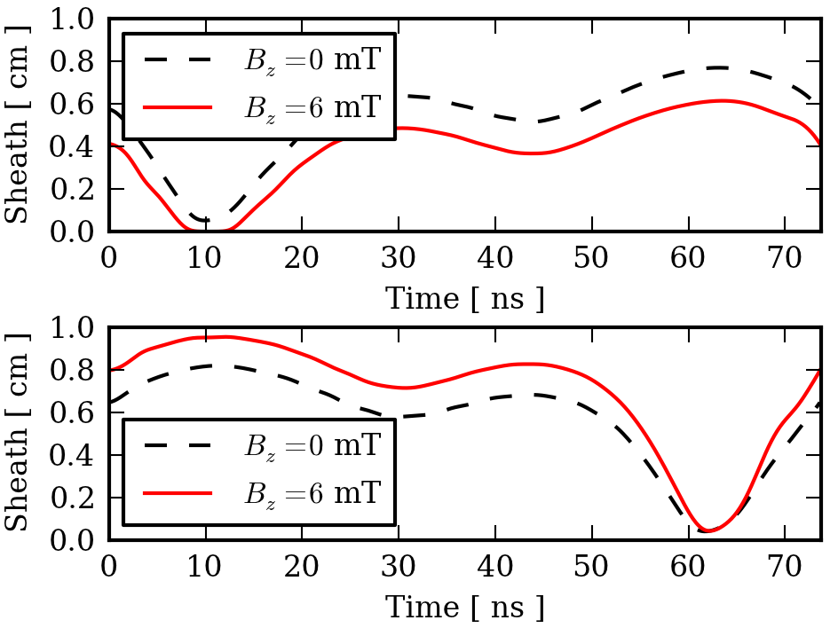
Due to the magnetically induced asymmetry, one can also observe that the sheath in front of the left driven electrode (which is in the magnetized region) is much smaller than the sheath in front of the right grounded electrode. The asymmetry of the electron density profile (and the ion flux) is the reason for the different sheath widths.
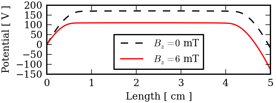
Figure 5 compares the temporal behavior of the sheath widths for the two different cases of both the driven (left) and grounded (right) sheath. While for case I both sheaths show very similar dynamics, for case II the left magnetized sheath is on average significantly smaller than the right non-magnetized sheath. This magnetically induced asymmetry results in a substantial DC self bias voltage (of about 130 V). This can be seen in figure 6, where the time-averaged potential profiles for the two different cases are compared. One can also find that the plasma potential is reduced from about 170 V (for the non-magnetized case) to about 100 V (for the magnetized case), which is expected.
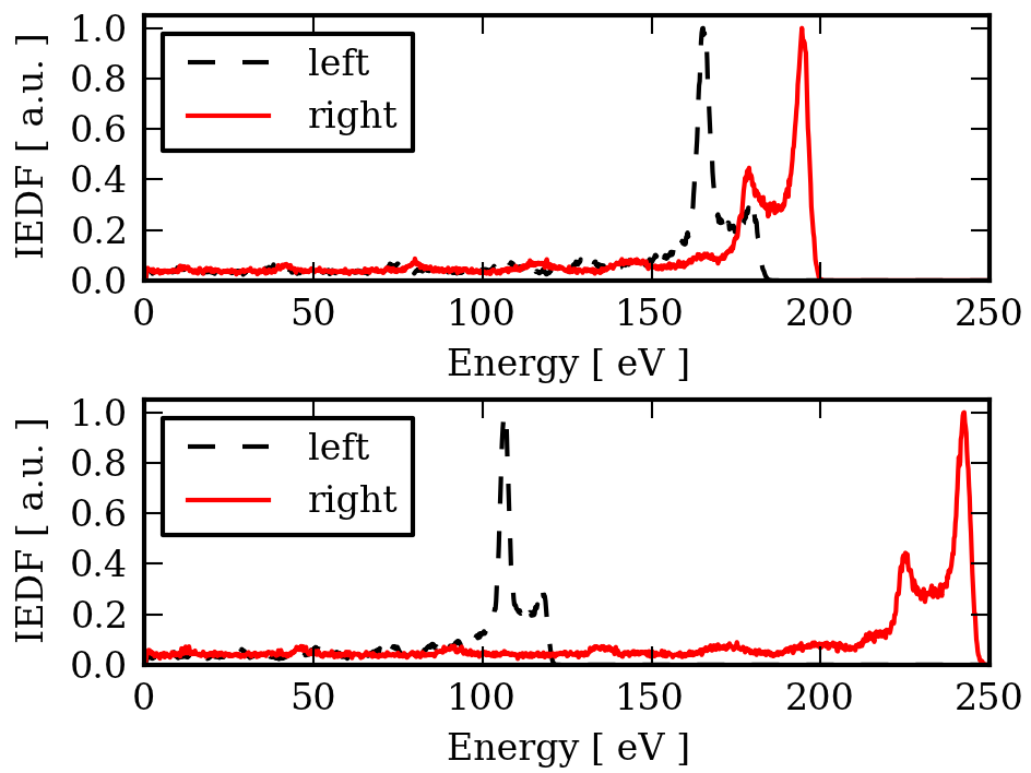
Figure 7 shows energy distribution functions of ions impinging the electrodes for both cases, without (top, case I) and with (bottom, case II) an external magnetic field. With a magnetic field the discharge is strongly asymmetric. One obtains very high ion energies at the right grounded electrode while the ion energy is smaller at the left driven electrode. This is clearly due to the DC self bias voltage mentioned before. For the non-magnetized symmetric case the ion energies at the left and the right electrode are almost equal. One can observe a small asymmetry in the IEDFs which is due to a small asymmetry in the sheath potentials. The reason for this is the difference of the sheath expansion and the resulting beams of energetic electrons. This effect has been previously reported by Schulze et al. schulze2010 .
IV.2 Electrical Asymmetry Effect in Magnetized CCRFD
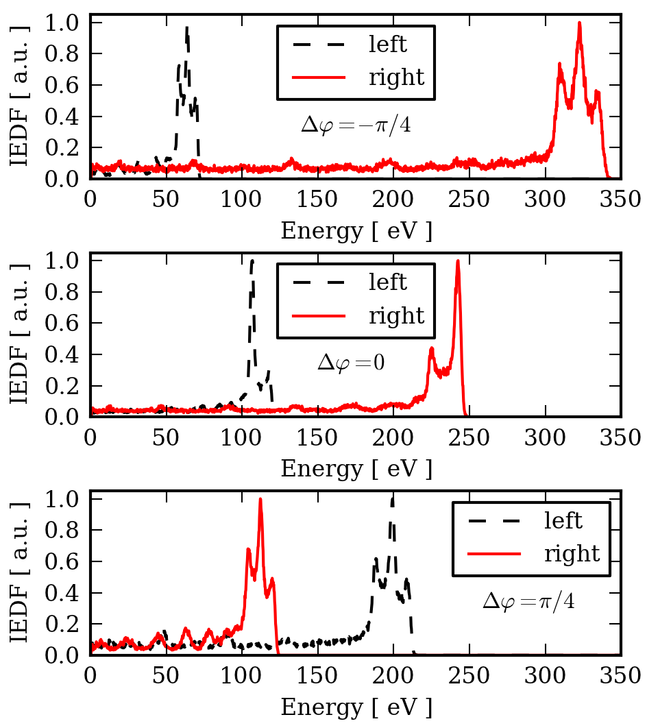
The parameter which controls the EAE and therefore the IEDFs is the relative phase between the two consecutive harmonics of the driving voltage . Using a spatially inhomogeneous magnetic field, which itself produces an asymmetry (as discussed above), one is able to modify the asymmetry using the EAE. One can argue, that the EAE can be used for the compensation or amplification of the asymmetry induced by the inhomogeneous magnetic field. However, in any case the two effects compete against each other. Here, we briefly discuss numerical results for case II (the magnetized case) for different relative phases, i.e., , , and .
Figure 8 shows the IEDFs for this scenario. One can observe that for the EAE can be used to amplify the magnetically induced asymmetry (in terms of increasing the ion bombardment energy at the right grounded electrode and its decreasing at the same time at the left driven electrode). For a relative phase of one obtains an over-compensation of the magnetically induced asymmetry. The role of the left and the right electrode changes. It is interesting to note that another knob for controlling the IEDFs could be the change of the absolute value of the magnetic field in conjunction with the EAE. However, this should not be discussed in the frame of a simple one-dimensional model, but should be studied by means of a more complete, at least two-dimensional model.
IV.3 Influence of the magnetic field on the sheath dynamics
In contrast to the electrons, the ions are not confined by the magnetic field. This is due to their large mass and a relatively low ion velocity. The main effect introduced by the external magnetic field is the efficient electron heating in the region where the magnetic field is high. When comparing the energy distribution functions of ions impinging the electrodes for the magnetized and the non-magnetized case, we can attribute the differences mainly to the different plasma density profiles (thus the ion flux towards the electrodes) and to the sheath voltages accelerating the ions. The IEDFs are mainly controlled by the sheath dynamics.
To justify this hypothesis we analyze the sheath dynamics using EST, which does not include any magnetic field effects. For this purpose we first compare the spatiotemporal sheath dynamics obtained from the PIC simulation for the magnetized case (case II) with the results from EST. As described in section III we extract the ion flux and the sheath voltage from the PIC simulation and use then as input parameters for EST.
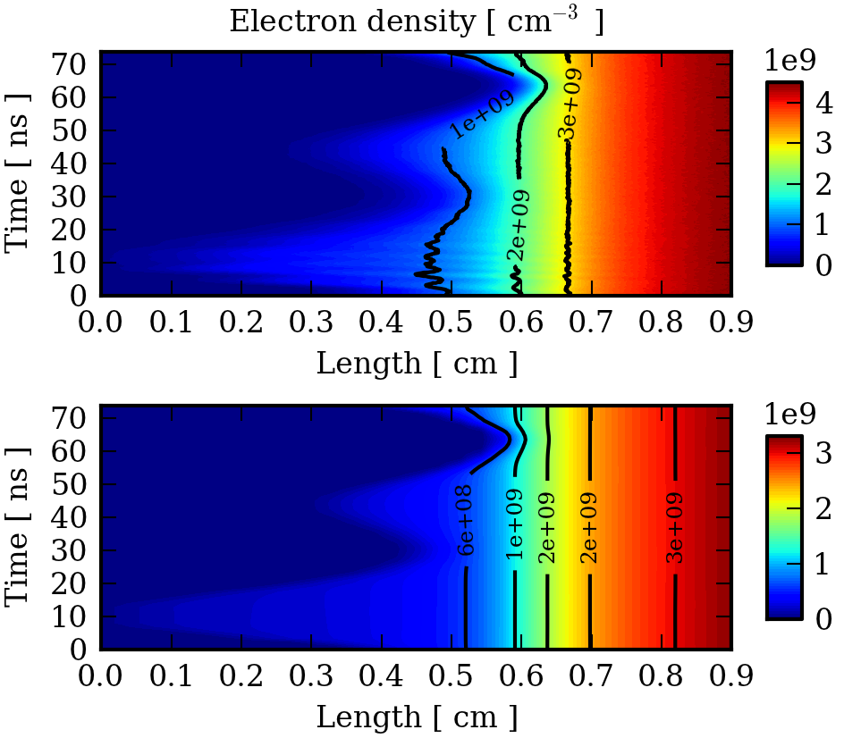
Figure 9 shows the spacetime dynamics of the electron density for both approaches. The sheath dynamics are in very good qualitative agreement. Deviations can be observed particularly near the sheath edge. This is due to the different collision models used in PIC and EST. While the PIC scheme allows for ionization collisions of electrons with the background gas, EST does not include plasma generation. Therefore one can observe a higher electron density in the PIC results. A second reason (which has to be proved) is nonlinear electron resonance heating due to the excitation of higher harmonics in the plasma current and thus the plasma series resonance mussenbrock2006a ; mussenbrock2006b ; czarnetzki2006 ; mussenbrock2007 . The higher harmonics are clearly visible in the sheath dynamics. Of course, this phenomenon due to nonlinear sheath bulk interaction is not included in EST results, since EST resolves the sheath only.
Figure 10 compares the IEDFs for the non-magnetized case I obtained using both PIC and EST. It is evident that both models are in excellent agreement, which is expected. Figure 11 shows the IEDF for the magnetized case II. The results are again obtained using both PIC and EST. Also for this case the results are in excellent agreement. Only minor deviations can be observed when comparing the magnitudes of the double peak structure.
It is interesting to note that EST yields the same IEDFs as PIC, regardless of whether the modeled sheath is magnetized or not. The reason is, that both the sheath dynamics and the ion motion in the sheath are mainly driven by the electric field, and only weakly affected by the magnetic field. We therefore argue that EST can be used for calculating IEDFs regardless of the nature of the discharge.
V Conclusions
In this work we analyze the effect of a magnetic field on the characteristics of capacitively coupled radio frequency discharges, with a focus on the energy distribution function (IEDF) of ions impinging the electrodes and the sheath dynamics. Using a well-justified one-dimensional Particle-in-Cell approach with Monte-Carlo collisions (PIC), we show that geometrically symmetric capacitively coupled radio frequency discharges can be asymmetrized by applying a spatially inhomogeneous static magnetic field. This magnetically induced effect is similar to the electrical asymmetry effect (EAE). We further show that the EAE itself can be (over-)compensated and even amplified. It this context it could be interesting to study the effect of the magnitude and the shape of the external magnetic field on the Electrical Asymmetry Effect in terms of the symmetry parameter introduced by Heil et al. heil2008 ; czarnetzki2009 . The symmetry parameter is defined as the absolute value of the ratio of the two sheath voltages. It can be expressed in terms of an algebraic model. However, it should be discussed in detail in the frame of an at least two-dimensional Particle-in-Cell code which is able to capture the whole discharge dynamics including the inherent inhomogeneity of the magnetic field and the phenomena related to it (e.g., particle drifts and magnetic mirror effects).
Finally, we find that the novel Ensemble-in-Space time scheme (EST) which resolves the sheath only, is able to provide IEDFs almost equal to the ones obtained from the fully self-consistent PIC simulation, regardless of whether the related discharge is magnetized or non-magnetized. As such EST may be used as an efficient postprocessing tool to obtain the IEDFs in many scenarios including non-magnetized and magnetized situations.
Acknowledgments
This work is supported by the Deutsche Forschungsgemeinschaft DFG in the frame of Collaborative Research Centre TRR 87.
References
- (1) B.G. Heil, U. Czarnetzki, R.P. Brinkmann, and T. Mussenbrock, J. Phys. D: Appl. Phys. 41, 165202 (2008)
- (2) U. Czarnetzki, B.G. Heil, J. Schulze, Z. Donkó, T. Mussenbrock, and R.P. Brinkmann, J. Phys.: Conf. Ser. 162, 012010 (2009)
- (3) E. Kawamura, V. Vahedi, M.A. Lieberman, and C.K. Birdsall, Plasma Sources Sci. Technol. 8, R45 (1999)
- (4) T. Mussenbrock, Contrib. Plasma Phys. 52, 571 (2012)
- (5) J. Schulze, E. Schüngel, U. Czarnetzki, M. Gebhardt, R.P. Brinkmann, and T. Mussenbrock, Appl. Phys. Lett. 98, 031501 (2011)
- (6) E. Schüngel, D. Eremin, J. Schulze, T. Mussenbrock, and U. Czarnetzki, J. Appl. Phys. 112, 053302 (2012)
- (7) D.B. Graves, IEEE Trans. Plasma Sci. 22, 31 (1994)
- (8) M.A. Lieberman, A.J. Lichtenberg, and S.E. Savas, IEEE Trans. Plasma Sci. 19, 189 (1991)
- (9) M.J. Kushner, J. Appl. Phys. 94, 1436 (2003)
- (10) S. Rauf, IEEE Trans. Plasma Sci. 31, 471 (2003).
- (11) D. Cheng, D. Maydan, S. Somekh, K.R. Stalder, D.L. Andrews, M. Chang, J.M. White, J.Y.K. Wong, V.J. Zeitlin, and D.N. Wang, US Patent 4,842,683 (1989)
- (12) E.L. Oster, US Patent 6,805,770 (1989)
- (13) M. Shihab, D. Ziegler, and R.P. Brinkmann, J. Appl. Phys. 45, 185202 (2012)
- (14) M. Prenzel, A. Kortmann, A. von Keudell, F. Nahif, J.M. Schneider, M. Shihab, R.P. Brinkmann, accepted by Journal of Physics D: Applied Physics (2012)
- (15) M.M. Turner, A. Derzsi, Z. Donkó, D. Eremin, S.J. Kelly, T. Lafleur, and T. Mussenbrock Simulation benchmarks for low-pressure plasmas: capacitive discharges, submitted to Physics of Plasmas (2012)
- (16) C.K. Birdsall, IEEE Trans. Plasma Sci. 19, 2, 65 (1991)
- (17) J.P. Boris, Proc. 4th Conf. Num. Sim. Plasmas, 3 (1970)
- (18) P. Mertmann, D. Eremin, T. Mussenbrock, R.P. Brinkmann, and P. Awakowicz, Comput. Phys. Comm. 182, 2161 (2011)
- (19) H. R. Skullerud, J. Phys. D 1, 1567 (1968)
- (20) A.V. Phelps, J. Appl. Phys. 76, 747 (1994)
-
(21)
LXCat (Electron Scattering Database),
http://www.lxcat.laplace.univ-tlse.fr, retrieved Jan 23, 2012 - (22) R.P. Brinkmann, J. Appl. Phys. 102, 093303 (2007)
- (23) J. Schulze, E. Schüngel, Z. Donkó, and U. Czarnetzki, J. Phys. D: Appl. Phys. 43, 225201 (2010)
- (24) T. Mussenbrock, R.P. Brinkmann, Appl. Phys. Lett. 88, 151503 (2006)
- (25) T. Mussenbrock, D. Ziegler, R.P. Brinkmann, Phys. Plasmas 13, 083501 (2006)
- (26) U. Czarnetzki, T. Mussenbrock, R.P. Brinkmann, Phys. Plasmas 13, 123503 (2006)
- (27) T. Mussenbrock, R.P. Brinkmann, Plasma Sources Sci. Technol. 16, 377 (2007)


