Tag Spotting at the interference range
Abstract
In wireless networks, the presence of interference among wireless links introduces dependencies among flows that do not share a single link or node. As a result, when designing a resource allocation scheme, be it a medium access scheduler or a flow rate controller, one needs to consider the interdependence among nodes within interference range of each other. Specifically, control plane information needs to reach nearby nodes which often lie outside the communication range, but within the interference range of a node of interest.
But how can one communicate control plane information well beyond the existing communication range? To address this fundamental need we introduce tag spotting. Tag spotting refers to a communication system which allows reliable control data transmission at SNR values as low as 0 dB. It does this by employing a number of signal encoding techniques including adding redundancy to multitone modulation, shaping the spectrum to reduce inter-carrier interference, and the use of algebraic coding. Making use of a detection theory-based model we analyze the performance achievable by our modulation as well as the trade-off between the rate of the information transmitted and the likelihood of error. Using real-world experiments on an OFDM system built with software radios, we show that we can transmit data at the target SNR value of 0 dB with a 6% overhead; that is, 6% of our packet is used for our low-SNR decodable tags (which carry up to a couple of bytes of data in our testbed), while the remaining 94% is used for traditional header and payload data. We also demonstrate via simulations how tag spotting can be used in implementing fair and efficient rate control and scheduling schemes in the context of wireless multi-hop networks, while pointing out that the idea of tag spotting is useful in the context of any wireless network in which control-plane information must travel beyond the communication range of a node.
keywords:
Wireless , Tag Spotting , Software Radios , Resource Allocation1 Introduction
Many of the challenges encountered in the design of wireless networks with multiple transmission and reception points stem from the quirks of wireless signal propagation. Using currently prevailing transmission techniques, wireless signals cannot be focused exclusively towards their intended recipient, making wireless an inherently shared medium. Wireless transmissions are local in their coverage, and, in general, no sender or receiver will have access to complete channel state information. Because of these characteristics, a wireless network is commonly modeled as a set of links among which interference may occur depending on the particular choice of senders transmitting at the same time. The effects of wireless interference are far reaching, affecting all network layers, from physical layer and medium access to flow control and user satisfaction. They extend beyond the space of a single host or a single link, as flows that do not share any hosts or links in their paths might in fact find themselves competing for resources. Its direct consequence is unfairness leading to flow starvation and underutilization of available resources. A study of the exact mechanisms through which interference leads to unfairness reveals problems at multiple network layers. The most general statements of these problems frequently preclude finding a decentralized and optimal solution. However, interference is a local disruption, and therefore leaves hope that a local, if imperfect, solution may be found.
Distributed algorithms often make use of local exchanges of information. This creates a need for a communication backplane capable of connecting each host to the set of hosts affected by its transmissions. This requirement is more cumbersome than it might seem at first sight, for successful data transmission at common data rates requires rather large signal to noise ratios. The capacity of links is however affected even by interferers reaching them at far lower signal levels. Connecting the recipients of interference with transmitters requires thus a communication backplane capable of operating over channels offering low signal-to-noise ratios. This, in turn, implies that constructing such a communication backplane will require designing a physical layer different from the standard physical layers used for high rate data transmissions. Further differences arise from the fact that, in a wireless environment designed to support primarily data transmissions over short links operating at strong signal levels, long range communication is at best opportunistic. Backplane communication receivers are therefore required to be able to discriminate actual backplane transmissions from high levels of background chatter. Moreover, in order to offer a significant improvement without further aggravating the interference problem, communications along the backplane should not create new interference constraints.
In this paper we propose a signaling scheme enabling the creation of a communication backplane which meets all the above requirements. Our scheme induces a low per-packet overhead, is resilient to high levels of noise and interference, and minimizes the disruption of data transmissions due to the interference that it induces.
Our first contribution is the design of tags, members of a set of signals designed to be easily detectable and recognizable in the presence of high levels of noise and interference, in the absence of time and phase synchronization and with only approximate frequency synchronization. Their increase in range over regular data transmissions is obtained in part through added redundancy. Tag signals are modulated using multitone modulation over a time duration that is larger than the duration of a regular data-transmitting tone. A tag is a distinct superposition of several tones whose frequencies are chosen according to the codewords of a binary algebraic code. On the receiver side, tags are recognized using a receiver based on spectral analysis.
What about interference caused by tags on data payload? OFDM, the prevalent modulation for data transmission in today’s wireless networks, used in this study as well, exhibits flat time and frequency power densities. We will prove that interference disruptions caused by tags are comparable to the ones caused by data transmissions.
Our second contriboution is an analysis of the performance of tags at different noise and interference levels and when making different design choices. Starting from detection theory principles, we derive, under a sufficiently general propagation model, the detection likelihood/false alarm likelihood curves at different SNR levels. We are particularly interested in quantizing the trade-off between transmitting more information (i.e. more bits per tag) and the corresponding increase in the likelihood of false alarm or misclassification. Our findings are later on compared to experimental results.
Our third contribution is the implementation and testing of Tag Spotting through experiments performed using a software radio platform in a testbed comprising senders, receivers and interferers. This series of experiments makes use of a tag family capable of conveying about one byte of information. The results of our evaluation support the conclusion that communication through tags is effective at SNR111Throughout this presentation we understand the noise part of the SNR figure to also include interference power, unless specifically noted otherwise. values as low as 0 dB and is robust to the effects of interference. In addition, through a series of channel simulations, we establish the possibility of constructing tags capable of conveying more bits of information and we survey the effects of design decisions on the system performance.
Our fourth contribution is the use of Tag Spotting in two applications, showcasing the performance improvements brought by the existence of a control plane able to reach all nodes within the interference range. Specifically, we use tags to efficiently implement a state of the art congestion control scheme for multi-hop networks which requires neighboring nodes, i.e, nodes that interfere with each other, to exchange control information in an effort to fairly share the available bandwidth. We also use tags in order to design and test a simple MAC-layer signaling mechanism meant to prevent the starvation of TCP flows in multi-hop wireless networks.
This paper is organized as follows: In Section 2 we give an overview of related work and indicate some congestion control and scheduling mechanisms that would benefit from the use of tags. Section 3 introduces multitone modulation along with a simple model for estimating the spectral footprint of multitone signals and discusses techniques for limiting inter-carrier interference. Armed with the conclusions of Section 3, we proceed in Section 4 to describe in detail the structure of tags and construct a tag detector capable of distinguishing tags from interference. Section 5 discusses in detail the rationale behind each design decision present in tag construction. Section 6 experimentally evaluates, using a software radio platform, the communication range of tags as well as the rate of false detections. It is shown experimentally that tags can be reliably identified at SNR values as low as 0 dB while the likelihood of false detections can be sufficiently limited. The same section evaluates the impact of noise, tag transmissions, and data transmissions, on each other. Section 7 presents an analysis grounded on detection theory principles of the effects of different choices available in the process of designing the modulation of tags and, more importantly, of the trade-off between the data rate of tags (i.e. the number of bits transmitted) and the likelihood of false alarms. Two examples of using tags to facilitate the implementation and improve the performance of congestion control and scheduling are presented in Sections 8.1 and 8.2. Finally, Section 9 concludes the paper.
2 Related Work
Communication and Detection Theory. Tag Spotting is closely related to a classic research topic in communication theory, namely information transmission at low signal-to-noise ratios. The motivation of this research has varied from securing the transmitted data such as in the case of spread-spectrum communication [1] to protection against interference in the case of the widely used CDMA standard [2] and to achieving long-range transmission [3].
Tags employ a multicarrier spread-spectrum modulation. They are clearly related to MC-CDMA[4], however they use a non-coherent modulation and do not use orthogonal codewords. Like multitone FSK [5], tags use a combination of tones in order to transmit information.
The design of the tag detector presented in Section 4 is based on the detection theory of multipulse signals with constant amplitudes and unknown phases. While the classical detector for such a situation is well-studied and understood (see, for example [6, 7]), it requires a precise estimate of the background noise level in order to set appropriate detection thresholds. Interference from competing packet transmissions will confront tags with different levels of background noise, making a precise and timely estimate impossible. Our detector is independent of the level of background noise, requiring only a base SINR as prerequisite for the accuracy of the detection. In the appendix we apply a theoretical analysis similar to the one of the classical detector in order to derive the detection/false alarm trade-off curves of our own detector.
Tags could in principle be constructed using well-established means of communication such as correlator-based detectors, standard spread-spectrum based modulations [8] or frequency shify keying. However, these either assume a flat channel, preliminary synchronization in order to eliminate frequency and phase offsets or do not try to limit the maximal power in their spectral footprint (for the latter one). The design of tags addresses all these concerns.
Physical Layer Extensions. In the wireless networking world, carrier sense [9] can be seen as an example of a message passing mechanism operating beyond the data transmission range. Closely related is the use of dual busy tones [10] in order to signal channel occupancy. A recently proposed physical layer extension, CSMA with collision notification CSMA/CN [11], aims at reducing the impact of collisions through an early termination signal sent by the receiver of the colliding packet. The transmitter-based detector uses self-interference cancellation techniques in order to improve the SNR of the reciprocal channel and detects the termination signal using correlation, in a manner similar to [12]. However, as the authors of both these papers find out, a correlation based receiver cannot function without prior channel and frequency offset estimation, which prevents their use for broadcasts over arbitrary channels, as in the case of tags.
Carrier sense, dual busy tones and collision notifications are binary signaling mechanisms, not suited for transmitting numeric information, as required by message passing protocols. Another recent physical layer extension [13] aims at realizing a side-channel over spread-spectrum based protocols through perturbations of certain chips comprising a transmitted symbol. These perturbations are in turn compensated for by the normal error correcting codes employed in data transmission, thus allowing in most cases for the payload to be decoded correctly, and they are also detected by a special pattern analyzer, allowing fo rthe transmission of side information. While the motivation and design constraints of this work are similar to ours, the design choices made in the creation of tags are very different. Most importantly, tags do not require the data transmission scheme to be spread-spectrum based.
The technology of software defined radios [14, 15] has acted as an enabler for some of the recent advances in multiuser wireless network research. It allowed, for example, the experimentation of techniques such as zigzag decoding [16], interference cancellation [17] or dynamic bandwidth adaptation [18]. Perhaps the most similar technique to the one presented in this paper is the one of smart broadcast acknowledgments, introduced in [19], in which multitone modulation is used for the purpose of simultaneously conveying positive acknowledgments from multiple receivers. Other recent advances that also make use of software radios for evaluation purposes include multi-user beamforming [20], fine grained channel access in which bandwidth allocation based on an increased number of carriers is coupled with frame synchronization used in creating an effective uplink OFDM implementation [21] and frame synchronization used in obtaining diversity gains [22].
Congestion Control and Scheduling. Prior works on congestion control for multi-hop wireless networks differ in the way in which congestion is reported to the source. One class of schemes sends implicit or imprecise feedback by dropping or marking packets [23, 24] in the tradition of TCP congestion control [25], or by regulating transmissions based on queue differentials [26] along the lines of back-pressure ideas [27]. Another class of schemes [24, 28] explicitly computes available channel capacity and then sends precise rate feedback, in the spirit of wired network congestion control mechanisms such as XCP [29] and RCP [30].
In an effort to tackle the complexity of creating optimal schedulers, recent work on medium access for multihop networks has proposed distributed algorithms capable of approximating the optimal solution [31] [32] [33] [34] [35]. A common theme here is the use of local, neighborhood-centered information in achieving a global solution. Our work is partly motivated by the recent development of a number of congestion control and scheduling schemes for multi-hop wireless networks that are based on the local sharing of information, such as, for example, [24], [36] and [37]. Local information is at the heart of several other wireless multi-hop problems: neighbor discovery [38], reliable routing [39], capacity estimation [23] and signaling congestion and starvation. The mechanism proposed in this paper offers an efficient way to implement the neighborhood-wide sharing of control information in the schemes mentioned.
While these schemes append control plane information to data packets and rely on packet overhearing, it has been recognized that this information needs to reach all nodes within the carrier sense range of a node of interest. The information sharing mechanism proposed in this paper eases the implementation of many of these ideas and improves their performance (see Section 8), as control information will reach nodes outside the data transmission but within the carrier sense range.
3 An OFDM Primer
An OFDM encoder uses an inverse discrete Fourier transform in order to encode a sequence of symbols into a set of tones over a finite time interval, from here on named either a frame or an OFDM symbol. Consider the sequence of length whose elements are chosen from a signal constellation, arriving for encoding at an IFFT (inverse fast Fourier transform) frame generator. The resulting signal will be generated according to the formula:

Passing to the continuous Fourier transform exposes a windowing effect and provides us with an insight into the spectral footprint of the generated signal. The discrete spectrum of an OFDM frame is illustrated in the upper half of Figure 1 and corresponds to the original encoded symbol sequence . Since the summed exponentials are bounded in time, their continuous transforms are sinc functions and the spectrum of the encoded signal is the sum of these sinc functions, as depicted in the lower half of Figure 1. The orthogonality of different signals is preserved: the peak of each sinc function is aligned with the zeros of all other sinc functions.
Let’s focus on non-coherent communication, i.e. we assume that the phase of each received signal is independently random, and try to derive a concentration result for the power leaked outside the intended transmission bandwidth. In Section 4 we will use this result in order to motivate that the modulation of tag signals exhibits a fast spectral decay and limited inter-carrier interference. The reasoning behind our approach is encompassed in Equations (1) and (2) below, which describe the effects of self-interference on OFDM signals and give the speed of their spectral decay. In the presence of a small frequency offset , the interference signal added by a carrier with unitary amplitude to a carrier placed positions away is
and in power terms,
| (1) |
It can be easily verified that the magnitude of the interference among two carriers does not depend on the absolute difference of carrier frequencies but only on the number of carrier positions separating them.
Consider now a carrier at carrier position zero and an infinite block of carriers starting at carrier position . The average power leaked by this block of carriers into the zero-positioned carrier can be bounded according to Equation (1) to be:
| (2) |
where we assume that symbols on different carriers are independent. The series in Equation (2) is rapidly converging.
Based on the observations above we conclude that replacing a single carrier through a block of random-phase, lower-bandwidth carriers that occupies the same part of the frequency band will sharpen the spectrum of a multitone signal and accelerate its spectral decay. Moreover, the insertion of a relatively small number of null-carriers will significantly reduce interference between two neighboring active regions of the spectrum. Creating the replacement carrier block calls for an increase in the number of carriers, and a corresponding increase in the time length of the OFDM frame, as described fully in Section 4.
4 Tag Spotting
High Level Design Overview. Tag Spotting uses a set of signals (tags) that are easily detectable in low SNR conditions. The design of tags is determined by a number of constraints. Firstly, due to their short timespan, the presence of multiple indistinguishable sources and the presence of varying levels of interference, the tag detector cannot perform accurate channel estimation, or achieve time, phase and fine frequency synchronization. Secondly, in order to protect competing data transmissions from further levels of interference, tags must abide by a maximal spectral power constraint, which prevents the use of a peaky transmission scheme such as multiple frequency shift keying (MFSK). Finally, a tag detector must perform identically in the presence of added interference, as long as the SINR remains unchanged.
To address these constraints, we employed a noncoherent communication scheme that spreads a tag’s energy over the frequency domain. In constructing tags, the number of carriers was increased from the one used in payload data transmission in order to sharpen the signal’s spectral footprint and ease spectral analysis through the discrete Fourier transform even in the absence of complete frequency synchronization. The symbol sequences encoded over the different carriers were chosen according to an algebraic code, thus adding extra redundancy.
The current section presents the details of tag construction. The following section will present the reasoning behind the design decisions made throughout the construction.
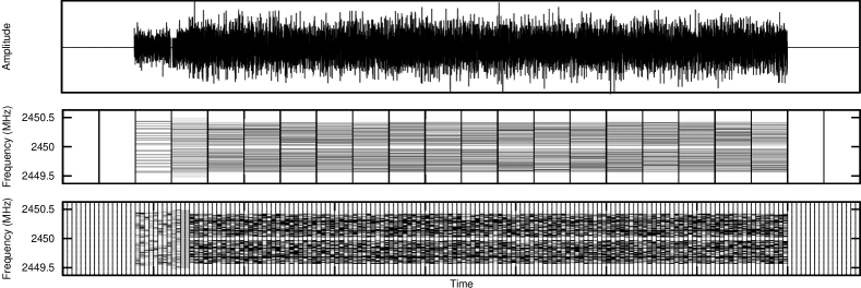
Multitone Structure. Figure 2 presents a packet transmission in the time domain representation as well as in two different time-frequency representations. The two time-frequency representations, pictured in the lower two panes, are realized by performing the spectral analysis of successive blocks of 512 samples (middle pane) or 64 samples (lower pane). As we will see, these lengths are natural choices for describing the structures of tags and packet payloads respectively. In the same representations, each vertical column corresponds to an analyzed block, while the horizontal line pattern present in each such column illustrates the block’s power spectral decomposition. In order to make the representation more meaningful, we have stripped tags and data frames of their cyclic prefixes and we aligned the boundaries of the analysis periods with the boundaries of tags and data frames.
The structure of a tag in frequency domain is depicted in the lower pane of Figure 4. Tags are encoded using 512 OFDM carriers while packet information makes use of 64 wider data carriers. Therefore, in time domain, a tag spans a period equivalent to eight regular data frames, while in frequency domain each “wide” data carrier corresponds to eight “thin” tag carriers. The transmission begins with a tag, whose spectrum can be observed in the third column of the middle pane, and continues with data frames containing synchronization data followed by the packet’s payload. To both tags and data frames we append a cyclic prefix which increases their respective lengths by -th.
The spectrum of a tag is constructed, at a basic level, by transmitting a symbol from a 0-1 (on/off) constellation in the frequency space corresponding to each of the wide carriers. Wide carriers are in turn grouped into groups of two neighboring carriers, and in each group only one of the two wide carriers will be active, carrying the entire power transmitted through the group. This last constraint renders the modulation inside each carrier group to be a form of binary frequency shift keying. Such a two-carrier group is depicted in Figure 3. On the receiver side, the tag detector operates in the presence of small, tolerable but unknown frequency offsets, which may cause power spillage from the active wide carriers to the inactive carriers. As illustrated in Figure 3, we chose to send the entire signal power allotted to an active wide carrier using the central four of the eight thin carriers corresponding to this particular wide carrier. We also chose to encode the tones sent on these four thin carriers using symbols of the same amplitude but which use uniformly independent random phases. Looking at Equation (2) , since the use of the random phases implies that the symbols transmitted over the different thing carriers are independent, it results that increasing the number of carriers and using random phases for the transmitted symbols reduce the amount of power leaked onto inactive wide carriers.222More precisely, Equation (2) predicts that under these circumstances the signal’s roll-off, considered anywhere in the frequency band, is compressed through a factor that equals the increase in number of carriers when replacing wide carriers with thin carriers.
A straightforward computation assuming a frequency offset distributed uniformly between zero and two thin carrier widths reveals that the expected power leaked is, in expectation, about 2.3% of the total power. Figure 4 further illustrates this aspect by presenting the spectrum of a received tag in the presence of a frequency offset equal to 10% of a regular carrier width. By comparing the distribution of the received signal power in the frequency bins corresponding to wide carriers (middle pane) with the structure of the transmitted tag (lower pane), it can be seen that the received power is concentrated in those bins which correspond to active wide carriers. As a note, the use of random phases in signal construction has one further advantage: it allows sampling tags from a larger signal set in order to limit their peak to average power ratio.
For tag construction purposes, eight of the wide carriers have been designated null carriers, while the remaining 56 carriers give rise to 28 two-carrier groups. Every tag can thus be naturally mapped to a 28-bit string in which each bit marks the choice of state in one of the groups.
Encoding. As it is common in communication system design, modulation is supplemented by a coding layer. The purpose of this layer is to create a subset of maximally differentiable signals, and to reduce the number of hypotheses tested.
The tag signal construction detailed above produces different basic tags, too many for efficient detection and insufficiently distinguishable from each other. A further restriction makes use of a 333The notation for codes used here is in the form where is the binary codeword length, denotes the number of distinct codewords and denotes the minimal Hamming distance between any two codewords. nonlinear code proposed by Sloane and Seidel [40]. Out of the basic tags only those having binary representations corresponding to the 60 codewords of this code are preserved. We discuss the use of other codes in Section 6.

Regular data frames spread the transmitted power over 48 carriers while tags make use of only 28 carriers. Since the average power spectral densities of used carriers in tags and data transmissions are equal, it results that the transmitted power in the case of tags is lower than the transmitted power in the case of data, as it can be observed in Figure 2.
Constructing a Tag Detector. Let denote the set of all tags and be the set of all data carriers activated when transmitting tag . Let denote the power of the received signal in the frequency bin corresponding to the -th carrier. Our detector does not assume the channel phase response to be uniform and can therefore be used in a wideband scenario. We compute the following quantity which we will name from now on tag strength:
| (3) |
Tag strength is compared against a fixed threshold and in case the threshold is exceeded a possible tag observation is recorded. 444This equation is similar to the one of the low-SNR multipulse detector with samples for a signal with unknown phase varying at each pulse: , at a given SNR value . Denote by the hypothesis that signal has been sent and by the hypothesis that no signal has been sent. That detector is based on the equation where is a constant (see [6, p. 293]); in our case, the correction factor can be seen as an approximation of , meant to remove the linear dependence of the threshold on the noise power , allowing thus for added noise-like interference.
Detection intervals have the same length as a tag from which the cyclic prefix has been removed and are spaced one tag cyclic prefix length apart. It results that successive analyzed intervals have significant overlap. Every transmitted tag will completely cover at least one detection interval. The detector processes every interval by first computing the Fourier transform of the contained signal and then computing, based on the resulting spectrum, the strength of each tag according to Equation (3). In order for a tag recognition event to be recorded, the corresponding tag strength must, firstly, exceed the threshold value and, secondly, be maximal among all tag strengths (for all tags) derived from detection intervals that overlap the current interval. A further detection metric effective in filtering off-band interference is computed for each detection interval by weighting the power levels in different carriers through the carrier’s position in the frequency band, summing the resulting values and afterward dividing the result through the total interval power. As long as the resulting “center of mass” is placed in the central quarter of the frequency band, the tag observations are considered valid, otherwise they will be attributed to off-band interference.

In order to reduce the number of intervals analyzed and the likelihood of false alarms, a simple carrier sense scheme is employed. The receiver maintains a running estimate of channel noise and processes only those intervals for which the SNR exceeds dB.
Overhead. Adding a tag to a packet incurs a transmission time overhead. Assume for now that only data packets are tagged and that a typical data packet has a payload of about 1500 bytes. Encoded using the parameters presented in Section 6, the payload will span 125 data frames, to which six synchronization frames are appended. A tag spans the equivalent of eight data frames and therefore its overhead is about 6.1% in terms of the normal packet duration. In some control schemes some of the data messages will not require tags to be piggybacked, allowing for a lesser overhead.
5 Motivating the Design Choices
The previous section has presented in considerable detail the structure of tags. While the above description is complete, the decisions taken in the construction of tags may well seem arbitrary. The purpose of the current section is to motivate every design decision taken in tag construction.
5.1 Multitone Structure
The design space of tag signals is frequency space. At the lowest level, tags use the same form of modulation in frequency space, using orthogonal signals over a finite time interval, that is used in regular data transmission.
OFDM. In an opportunistic reception system that searches for the short occurrences of tags, the price of exact frequency synchronization and of exact channel estimation should be avoided. Tags are therefore transmitted and received without performing channel estimation or frequency synchronization. This raises a challenge in solving inter-carrier interference.
Remember that the choice of OFDM for data transmission is linked to the propagation behavior of wireless signals. Since sine signals are the eigenfunctions of the wireless channel, the use of orthogonal sines along with an appropriate cyclic prefix is meant to prevent any channel-caused interference among the different transmitted symbols. The limited timespan of the transmission interval precludes the use of actual sines or any other signals with narrow support in the frequency space. As it was discussed in Section 3, the actual signals used in the transmissions have a slowly-decaying spectral footprint. In OFDM data transmission, the inter-carrier interference which the slow spectral decay entails is avoided through exact frequency synchronization, using the fact that in frequency space the zeros of the base sine-like signals align with the peaks of all other signals in the base set. In contrast, for tags, the packing of noncoherent carriers into larger building blocks reduces the amount of power leaked among the frequency bins corresponding to thick carriers. This reduction in leaked power allows the system to function as intended even when the receiver is not frequency-locked onto the transmitter. The lack of frequency synchronization together with the lack of an estimate of the channel phase response at different frequencies also leads to uncertainty regarding the phase of the transmitted signal. The use of a noncoherent encoding allows us to overcome the lack of knowledge of the channel phase response without further complications. It could be argued that these channel characteristics should be measured in advance. However, our receptions are at best opportunistic, and the channel could be any one of a multitude of fast changing channels between any pair of hosts. Certainly, obtaining an exact estimate of the channel response and of the frequency offset, at the low SNR levels for which our system is designed, would greatly complicate the tag transmission problem.
Fading. Another characteristic of wireless channel transmission, frequency-selective fading, provides the rationale for the use of groups of two carriers as a encoding unit: since neighboring data carriers are likely to experience similar fading and since any of the codewords makes use of either one or the other of the two carriers in a two-carrier group in order to encode a bit value, fading over a two-carrier group will not induce a bias towards any of the hypotheses that a particular codeword has been transmitted. The received power and the likelihood of detection may well decrease due to fading. However, when considering a given overall signal to noise ratio, i.e. computed over all the carriers, the detection probabilities over fading and non-fading channels are quite similar, as shown in Section 7, while the false alarm probabilities are the same. We can conclude that this particular design decision manages to overcome most of the difficulties that fading introduces in tag detection.
5.2 Constructing a Tag Detector
It is worth mentioning here a significant difference between the main purpose of a tag receiver and the purpose of a communication system receiver. While a communication system receiver is meant to accurately distinguish between a number of hypotheses corresponding to signal transmissions under the assumption that an actual transmission has occurred, the tag receiver listens for the most part to noise and background chatter. The main task of a tag receiver is therefore to detect, with sufficient confidence, a tag transmission when one occurs and, if possible, to correctly identify the transmitted tag. Tag detection is therefore a detection problem more than a communication problem and the design of the detector reflects this fact. The probabilities of false alarm allowed in the case of tags are well under the typical probabilities of misclassification allowed in a communication system, since the occurrence of tag transmissions are assumed a priori to be rather rare events. False alarms weigh in more heavily when compared to the total number of detected tags. Due to the fact that tag detection is essentially a detection theory problem, we choose the detection metric (probability of false alarm versus the probability of detection) to be the main measure of tags performance. The secondary metric considered will be the probability of misclassification of a transmitted tag. The experimental section will reveal that this probability is negligible due to the high threshold required for a positive tag detection, even when using a rather large number of codewords.
Detecting Patterns. In general, tag observations occur over short intervals of time and channel conditions change too frequently for the receiver to obtain and update an accurate noise and interference power estimate. The only assumption made in the following is that the spectral envelope of the noise and interference signals is flat, an assumption that can be justified in the case of data networks using OFDM-based encoding. We design therefore our modulation scheme and our receiver to use as a detection indication not the sheer amount of power received but rather the concentration of the received power into pre-determined frequency bins. The receiver detects a transmission event whenever the concentration of the received power (the ratio of the power received in the designed frequency bins to the overall received power) exceeds a certain threshold. Therefore, the receiver searches not just for the presence of a signal but for a certain spectral shape. The fact that a power ratio measurement is used as a detection metric guarantees an universal receiver in a wider sense: the probability of detection for a threshold value chosen as the receiver parameter will only increase with increasing SINR. A standard detector is denoted as universal when a similar guarantee exists in terms of the SNR.
Tags and FSK. The attentive reader might have noticed that a simpler encoding scheme might have provided a similar detection/false alarm performance trade-off without the use of an algebraic code. Frequency shift keying simply concentrates the available power into the frequency space corresponding to one of the available carriers, thus offering similar received power characteristics. However, FSK has a large power spectral density, due to the fact that all the transmitted power is effectively concentrated in one point of the frequency spectrum, which makes it undesirable in a network environment, where we would like to guarantee a certain flat envelope for the frequency spectrum of our transmission, with a fast decay outside the data band. Our choice of modulation limits the transmitted power at any given frequency, resulting thus in a flat spectrum, similar to the one corresponding to OFDM data transmissions. The experiments in Section 6 verify that the typical interference effects of tags on competing data transmissions are not worse than the interference effects caused by normal packet data transmissions sent at a similar overall power level, which would not be the case if tags were modulated using FSK.
Choosing the number of active carriers. In Section 4 it was mentioned that tags are a specific form of multiple frequency shift keying (MFSK), a modulation which makes use of multiple noncoherent carriers transmitted simultaneously as a single symbol. A key parameter of MFSK is the number of transmitted carriers. Having chosen the MFSK modulation and the power ratio detector as the basic building blocks of our system, we must find next a value of this parameter that offers reasonable detection performance while also allowing for the construction of a large set of tags. As a definition of performance, we seek to minimize the probability of false alarms while preserving a certain probability of detection. In Section 7 this measure of detection performance is evaluated, as a function of the number of carriers transmitted, in the case of a detector that is searching for a single tag. It is revealed that, for a detector operating at a target SNR of 0 dB, the optimal allocation of power uses a bit less than half of the available carriers. Therefore, the decision to use exactly half of the carriers in the modulation does not impact the detector’s performance, while the same decision eases the use of an algebraic code.
5.3 Encoding
Families of Codewords. The decision to use exactly half of the carriers in the construction of tags is motivated by the details of constructing a tag family. In particular, we look at the relationship between tags and the binary codes used in their construction, namely codes over the same number of bits as the number of thick carriers. The simple binomial expansion indicates that the binary strings whose weight is half this number of bits are most numerous. We expect that for small Hamming distances the codes of this particular fixed weight would have more members than codes constructed using any set of binary strings of a different fixed weight. Our construction, which converts codeword families constructed over a number of bits equaling half the number of thick carriers into families of codewords of fixed weight over twice that length, is almost optimal, as it can be checked using tables of optimal known codes of fixed weight. Moreover, this construction allows for the use of well-known algebraic codes in tag construction and therefore leaves open the possibility of developing fast algorithms for identifying the most likely codeword in the case of large codeword families, in a manner similar to the identification, in communication systems, of the most likely transmitted codeword based on receiver soft symbol values.
Construction Procedure. Based on this description of the intricacies of tag construction we are now able to give a general procedure for constructing a set of tags that meet a desired set of performance criteria. Firstly, a codeword family that guarantees a low enough probability of misclassification at the target SNR while offering a sufficient number of different codewords must be selected. The probability of misclassification is computed in this step using Monte Carlo simulation, as presented in Section 7. Secondly, again using Monte Carlo simulation, as presented in Section 6, the tag designer must determine the probabilities of false alarm for the chosen tag family. The probability of detection can be more readily computed since it does not depend on the choice of codeword family but only on the number of carriers that a codeword uses. This process must be iterated until a suitable trade-off between the number of codewords available, the probability of detection and the probability of false alarm is achieved. When satisfactory results cannot be achieved, the tag designer may increase the time length of tag through the use of a larger FFT window and a correspondingly increased number of thin carriers, adding more redundancy to the signals.
6 Evaluation
6.1 Experimental Setup
(a) System Parameters The experiments were conducted using two USRP boards [14], one transmitter and one receiver, in an indoor environment without line of sight and with multiple concrete walls between the sender and the receiver. The GNU Radio software suite was used for signal transmission and recording. The carrier frequency chosen was 2.45 GHz and the bandwidth of the system was set to 1 MHz. In order to obtain a linear channel suitable for OFDM transmission without distortion effects introduced by the transmitter mixer and the receiver, the signal has been oversampled by a factor of four on both transmitter and receiver sides. The system uses the Schmidl and Cox algorithm [41] for packet detection and initial CFO estimation and the Tufvesson [12] algorithm for block boundary detection. Channel gain is measured using the preamble, while phase response is tracked using four pilot carriers and a linear phase interpolator. The symbol constellation used was 16-QAM. Packet payload was encoded using a rate punctured Trellis code. The resulting link speed is 2.4Mbps.
While the design of an efficient OFDM transmission and reception system is not the focus of this presentation, having a viable system was a precondition for showing that any interference effects produced by our set of header tags are comparable to interference effects caused by data transmissions and by environmental noise.
(b) Experiment Description. We performed three series of experiments intended to evaluate the impact of decreasing the signal to noise ratio on the effectiveness of tag spotting, the impact of rising interference power on tag spotting and the disruption caused to data transmission by interference in the form of tags. In order to determine the likelihood of false alarms, we have conducted a further series of experiments using half minute-long recorded signal sequences containing ambient radio noise pertaining to standard 802.11b/g transmissions in an office building occupied by numerous wireless networks in order to measure the detector’s robustness to different kinds of radio interference. We have also evaluated through simulations the likelihood of misclassifications.


(c) Metrics
- Tag Strength
-
is the quantity defined in Equation (3), the primary metric for deciding whether a tag observation will be recorded. It is a measure of the ratio of power contained in the frequency bins allotted to a given tag and the total received power. In order for a tag observation to be recorded one of the necessary conditions is that the tag strength must exceed a threshold value . In all experiments presented was used, which was chosen using the theoretical performance curves derived in Section 7. This choice of threshold accomplishes two goals: it is high enough to correspond to a low rate of false alarms, as verified through the experimental results presented in the current section (see Figure 5d) and it is low enough to allow detection at the target SNR values. Using the naïve assumption that noise (and interference) power contribute equally to the power levels detected in the different frequency bins, the SNR value that corresponds to this threshold can be derived to be about 0.4 dB.
- Symbol Error Rate (SER)
-
is measured for the payload of all correctly identified packets, that is, packets for which the packet detection, block boundary start estimation and CFO estimation succeed. It is the primary metric for estimating the effects of various noise and interference levels on data transmission. This metric was considered more fundamental than the bit error rate(BER), which is heavily dependent on the type of coding employed, a system design parameter that varies largely in current designs.
- Probability of Detection ()
-
is defined as the probability that a header tag will be correctly detected and identified at different SNR and SINR levels. It is the primary metric for the success of tag spotting.
- Probability of False Alarm ()
-
is defined as the likelihood that, in any given detection interval, noise and interference will cause a spurious tag detection and identification in the absence of a tag transmission.
- Probability of Misclassification ()
-
is the likelihood of incorrect tag identification in the presence of a tag transmission.
(d) Practical Considerations. The tag detector presented in Section 4 is unable to compensate for frequency variations between the sender and the receiver. The structure of tags and the detection method described makes it possible to tolerate frequency offsets of up to two thin carriers, or about 4 kHz, without perceivable performance impacts. We have found that the clock jitters of the USRP radios are well within this limit, however different radios have initial frequency offsets of up to 200 kHz, necessitating a supplementary calibration step before each experiment. We assume the effects of Doppler spread to be minimal, i.e. a near-static scenario.
In a practical scenario the clock components could be replaced with more accurately designed/packed counterparts, and therefore we conclude that constructing self-sufficient tag detectors is possible. Increasing the baseband bandwidth from the relatively narrow bandwidth of the USRPs (1 MHz for OFDM experiments) to the standard 20-40 MHz of WiFi would enlarge the thin carriers and correspondingly allow for larger frequency offsets which would make tags even more robust.
6.2 Experimental Results
(a) Impact of Noise. The first series of experiments tries to quantify the range effectiveness of tag spotting in the presence of different levels of noise, in an interference-free environment.

The transmitter was configured to send sequences of 100 packets with random header tags. On the receiver side the transmitted sequence was decoded and the sequence of detected tags was compared to the original transmitted sequence, in order to obtain an estimate of the detection probability . The decoded symbol payload of received packets was compared with the known symbol payload on the transmitter side in order to estimate the SER . The transmission’s SNR was estimated for each detected packet using a low-pass filter-based average power estimator. The power level of the transmitter was varied between levels spaced 3 dB apart, resulting in different channel SNR values.
Figure 5a illustrates the results obtained. The upper pane shows the Symbol Error Rate (SER) for the payload as a function of the Signal to Noise ratio (SNR). The curve is typical for a receiver employing 16-QAM modulation, however the receiver appears to exhibit an error floor at the higher SNR values measured. At SNR values of 20-25 dB, the system can sustain data transmission, when using a typical error-correcting code. This curve serves as a reference for the next experiments, in which noise-based disruptions will be replaced with data-like interference and tag-like interference.
The middle pane shows the Tag Strength as a function of the SNR. The curve decreases steadily as the SNR decreases, reaching the threshold value around 0 dB.
Finally, the lower pane shows the probability of detection as a function of the SNR. It can be seen that the probability of detection is close to one over the entire range considered.
(b) Impact of Interference. Figure 5b present the results of the same experiment in the presence of a second source transmitting an uninterrupted stream of payload-like data. As before the upper pane plots the Symbol Error Rate, the middle pane the Tag Strength, and the lower pane the probability of detection, all as a function of the SNR. The SER has a slightly different behavior in this case, due to the presence of a different type of interference, as can be seen when comparing the SER curve in the presence of data interference with the SER curve in the presence of just noise. The other quantities of interest, tag strength and the probability of detection remain essentially unchanged. The probability of detection climbs a steep curve and quickly settles close to one. We conclude that the tag detector acts almost identically in the presence of pure noise or noise combined with temporary interference.
(c) Impact of Tag Interference on Data. Figure 5c presents the effect of tags on data transmissions. The SER curve is very close to the SER curve of Figure 5a, demonstrating that interference from tags does not increase the error likelihood beyond the error likelihood in the presence of comparable levels of noise.
(d) Likelihood of False Alarm. Figure 5d presents the dependence of the average time in-between false alarms on the threshold , when analyzing recordings of ambient WiFi traffic. Carrier sense has been disabled in this experiment and every input detection interval is analyzed. These results support our choice of detection threshold, since false alarms occur at a rate of less than once every 20 seconds.
(e) Likelihood of Misclassification. Figure 6 presents the dependence of the probability of misclassification on the receive SNR when tags are constructed using either the code mentioned in Section 4, a few extended BCH codes with smaller minimal distance or an unencoded modulation. No lower tag strength threshold was employed. This plot reveals that, for all these schemes, misclassification does not occur at the targeted signal levels. More details on the significance of this result will be given in the next section.
(f) Choice of algebraic code. The choice of algebraic code affects two quantities of interest, and . It has already been noted that, for a large class of codes, the probability of misclassification is negligible at the targeted signal levels. On the other hand, the probability of false alarm will increase as the number of codewords increases, as illustrated in Figure 5d, due to the presence of supplemental hypotheses. It results that there is a trade-off between the number of bits of information available per tag and the desired rate of false alarms.
6.3 Tag Range
The possible use of tags in wireless multi-hop networks prompts us to calculate the increase in range, expressed in distance terms, that transmission through tags brings over regular data transmission. It is well-known that power decay exponents are highly dependent on the environment. Measurements of signal propagation in the 2.4 GHz band described in [42] reveal a dependence of received power on distance of the form where the exponent varies from 3 for line of sight propagation to about 6 for non-line of sight propagation. Regular data transmissions using the 16-QAM modulation present in our system necessitate a SNR value of about 20 dB while tags are detectable at a SNR value of 0 dB. It results that the ratio of the range of tag communication to the range of the data transmissions can be, depending on the power decay coefficient, anywhere between 2.15 and 4.65.
7 Performance Analysis


Section 4 has described the design of tags and introduced an universal detector555a detector for which, for any chosen probability of error , the corresponding probability of detection can only increase when the SINR is increased. A universal detector is particularly suited to our purposes, given the unpredictable nature of interference power. that does not require an estimate of the combined power of noise and background interference. However, the classic theoretical results on the detection and false alarm probability distributions are not readily applicable to our more complicated tag detector. In the following we will analyze, using rather conservative fading models, the performance achievable by a few particular tag families. At first we will consider the performance achievable when searching for a single tag signal, after which we will generalize to larger families of tags. The analysis will make use of two fading models, a narrowband fading model and a wideband fading model which assumes Rayleigh propagation. Due to the limited timespan of tags, these two models describe short-term fading effects only.
Single Tag. Let us consider a tag . In what follows, we will denote by the number of two-carrier groups used in the tag’s construction. Assume that, for each thin carrier, the receiver noise has power and its distribution can be modeled by a complex Gaussian random variable . We further assume that for the active thin carriers the average signal power in the frequency band corresponding to any carrier is . Under the assumption of narrowband transmission and without including the receiver noise contribution, the received signal obtained after demodulating one of the carriers can be modeled as a circularly uniform complex variable of constant amplitude , while in the case of wideband transmission the signal is modeled by a complex Gaussian random variable . Assume that each thick carrier is composed of thin carriers, out of which are active. In the case of the system presented in the previous section and . Let denote the set of thin carriers activated when tag is transmitted, represent the thin carriers that, while they are not activated, belong to active thick carriers and the thin carriers that belong to unactivated thick carriers. In accordance to the definition given when introducing the tag detector, we denote through the set of all thin carriers belonging to activated thick carriers, regardless of whether they are active or not. Let be the complex values obtained after computing a fast Fourier transform of the real and complex components of a sampled tag signal, i.e. the received signal values corresponding to the various thin carriers. Let denote the norm.
Under the assumption of independent Rayleigh fading, it results that for each active thin carrier the amplitude of the received signal is distributed according to a complex Gaussian random variable . Choosing a threshold value for the quantity defined in Equation 3, we can write the probability of detection as:
| (4) |
or
| (5) |
It results from the previous paragraph and due to the independence of the circular random variables considered that the sums in the above equations can be written using the Chi-Square distribution with components, denoted through . Namely , and .
In the case of narrowband fading, the amplitude of the received signal for each active carrier is constant. Therefore the first of these sums can be written using the noncentral Chi-Square distribution with parameter . We write .
The probability of false alarm in the case of a single tag (and a single tested hypothesis) can be obtained by setting in the above formulas. Therefore, writing the ratio of the two Chi-Squared random variables using a random variable that follows the Fisher-Snedcor F-distribution[44], ,
| (6) |
Figures 7a and 7d present the detector’s behavior at different values in the case of wideband and narrowband signals, respectively. 666The SNR figures are computed using the power and noise figures for a thick carrier, that is .
Choosing the number of active carriers. Consider in the following a problem mentioned in Section 5, namely the optimal number of thick carriers that should be activated during a tag transmission in order to maximize the performance of the detector. Let denote the total number of thick carriers. In order to obtain closed-form results, we use a simplified model of tags in which we set , that is active thick carriers will use all thin subcarriers for transmission. Let be a random variable generated using the corresponding Fisher-Snedcor distribution, . Under this assumption we can simplify the formulas for the probability of detection and false alarm in the wideband case to: and
It results that the probability distribution of the receiver response corresponding to detections is just a scaled version of the probability distribution corresponding to false alarms. We introduce a new performance measure in order to characterize the performance change due to the choice of . Let be the value of for which , at a SNR value of 0 dB. Figure 8 plots the behavior of , for a detector with a threshold , for different values of , when . The quantity plotted represents the value of the tail of the probability of false alarm in the typical detection region.
Families of Tags. The next point in our analysis will be considering the situation in which the detector searches for multiple hypotheses. Assume therefore that the tag is a member of a family of tags , as described in Section 4. It can be readily observed that both in the narrowband and wideband cases the probabilities of detection remain unchanged. The probability of false alarm can be rewritten as:
where .
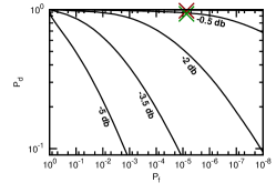
Figures 7b and 7e present the detector’s behavior, evaluated through Monte Carlo simulation, at different SNRs in the case of wideband and narrowband signals, respectively for the code mentioned in Section 4. In particular, Figure 7e compares the theoretical predictions with the experimental results presented in Section 6. The green cross at the top of the figure presents the experimentally measured detection probability for tags in the presence of background noise only, at an SNR value of 1 dB, as shown in in Figure 5a, while the red cross presents the theoretical value at the same SNR. The experimental data and the theoretical curve, which indicates a probability of detection nearing one, are in agreement.
The power levels on the carriers are being summed up in the hypotheses in different ways. Since the variables that are summed up are chosen from the same set, the probability that the maximum present in the function will cross any chosen threshold is significantly lower than what the sum bound on the individual probabilities of errors associated with the different codewords would predict.
The simpler quantity can be bounded using an initial symmetrization step [45] and deriving, using generic chaining [46], a Dudley-like inequality [47] on the probability that the maximum exceeds any given threshold. The resulting bound limits the increase of the necessary threshold, for any fixed probability of false alarm, to a quantity of the form where is the number of codewords used. For reasons of space we have not included the derivation of the bound.

For the code construction using the two-carrier groups presented in Section 4, a simple upper bound on the probability of false alarm can be derived by considering the case of the simplest code, which has the largest probability of false alarm of all possible codes since it includes all possible codewords . Consider a set of pairs of Chi-Square distributed random variables and let and represent the maximum and minimum, respectively, in each pair. The probability of false alarm can be thus written, for the afore mentioned code, as:
8 Applications
8.1 Congestion Control
In this section and the next one we present the use of Tag Spotting in two applications aimed towards obtaining a fair resource allocation in multi-hop wireless networks. We would like to emphasize that attaining a fair distribution of resources when using a wireless medium is, in our opinion, a neighborhood-centric problem. We explore the structure, the granularity and the rate of information that hosts within a neighborhood should exchange in order to solve the fairness problem At the medium access layer, all hosts must be able to gain access to the wireless channel. At the transport layer, all flows must be able to attain a sustained transfer rate comparable to the transfer rates of flows with which they compete, i.e flows that share the same wireless neighborhoods.
In a wireless setting, congestion is not always primarily experienced by the flow that causes it and a neighborhood-wide signaling mechanism becomes necessary.
With this in mind, we extend WCP [24], a recent AIMD-based scheme from the congestion control literature, by using Tag Spotting for communicating congestion notifications, and we assess the achieved performance of both the original WCP protocol and its extended derivative through simulations. In the original WCP, there are two types of information broadcasted by each node in data and ack packets: a congestion bit that indicates congestion events to its neighbors and the maximum of the round trip times (RTTs) of flows traversing it, a metric used in achieving a max-min fair allocation. This maximum RTT is then used to pace the rate increases of the AIMD controllers which set the rates of the flows traversing the neighborhood. Both loss rates and delays experienced by competing flows passing through a congested neighborhood may vary widely, significantly more than in wired networks. This causes the senders’ AIMD controllers to increase their rates at significantly different paces following a congestion event, unless a common loop duration is used. For more details on WCP, the interested reader is referred to [24].
We have simulated the performance of WCP using the Qualnet network simulator [48]. We have extended Qualnet’s physical layer simulation in order to also handle the likelihood of tag detection using the detection probabilities measured in Section 6. The content of tags is composed of one congestion bit and a field that encodes, on a logarithmic scale with base , the value, in milliseconds, the longest RTT of all flows traversing the tag emitter. We call the tag-based implementation of WCP, WCP-Tags. For the original WCP we have used a broadcasting mechanism that shares the same information as WCP-Tags, however the limit SNR for broadcast detection has been set at the same value at which successful payload data decoding occurs, since the original WCP broadcasts are inserted into the payload of data packets. All hosts use the regular 802.11 MAC for ad-hoc networks with default simulator values, with the only modification that the number of allowed MAC layer retransmissions has been doubled from its default value in order to decrease the rate of packet drops and increase the likelihood of tag reception.
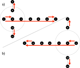
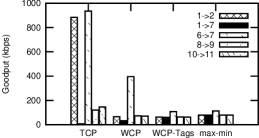
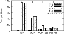
Figure 9a illustrates a textbook configuration for evaluating congestion control protocols in wireless environments. The two short flows on the outside of the central chain of nodes are within the transmission range of node 2, and we can therefore expect that the two variants of WCP will have similar performance. Figure 10a illustrates the rates obtained by TCP, original WCP (“WCP”) and the tag-based implementation of WCP (“WCP-Tags”). It can be readily observed that, while TCP leads to starvation of the central flow, both WCP and WCP-Tags manage a fairer rate allocation.
Discussing the results of these experiments requires taking into account, above all, the fairness achieved and secondly the throughput. It is well known that supporting a long flow in a wireless multi-hop network is possible only at rates significantly lower than the maximal link speed [49]. Any increase in the rate of the long flow in the figure will involve a drastic reduction in the rates of the other, shorter flows. To make this point more precise, we compute using brute force simulations and the theoretical framework in [50] the max-min rate allocation for these flows and compare it to the other allocations. It is evident that both the original WCP and WCP-Tags yield rates which are close to the max-min optimal rate allocation.
Figure 9b illustrates a variation of the previous topology in which the original WCP cannot effectively signal congestion between the involved hosts, due to the fact that some hosts are within the interference range but outside the data transmission range of each other. In particular, under the original WCP node 2 cannot inform nodes 8 and 10 that it is congested and the long flow is almost starved, similarly to what happens under TCP. In contrast, WCP-Tags does not starve the long flow as nodes 8 and 10 reduce their rates once they receive notifications through tags that node 2 is congested. The rate allocations achieved by the three protocols as well as the max-min rate allocation for this topology are illustrated in Figure 10b. As before, WCP-Tags yields rates which are close to the max-min optimal allocation.
8.2 Scheduling
A large class of scheduling algorithms for wireless multi-hop networks are centered on ideas such as queue equalization using backpressure [31] [37], broadcasting local congestion indications [23] or creating a computationally tractable approximation of an optimal schedule [32] [33]. Some of the benefits of schemes that use local communication will be illustrated in the current section through the evaluation of a rather simple scheduling scheme, designed as an extension to the ad-hoc mode of the the 802.11 MAC. The simple mechanism presented here targets some of the unfairness effects introduced by the 802.11 MAC which may lead to flow starvation.
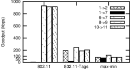
Consider again the topology illustrated in Figure 9b. The results of Section 8.1 have already shown that using a standard 802.11 MAC in conjunction with TCP drives the longest flow in this topology into starvation. Our solution preserves TCP as the transport protocol but seeks to relieve such severely disadvantaged flows by enhancing the scheduling algorithm. The key to achieving this goal is an exchange of tags conveying a meaningful measure of starvation, namely the average delay of the packets currently enqueued for transmission.
The hosts observe all detected tags and decide that a host in their neighborhood is starved for medium access whenever they receive a tag conveying an average queueing time which is at least 32 times larger than their own average queueing time. In this case the tag receiver will enter a silence period of 15 milliseconds, allowing the starved host to gain access to the channel and transmit its packets. These numbers are not particularly optimized since our focus is to showcase the benefits of using tags in scheduling with a very simple addition to 802.11, rather than to provide a fully optimized and tested solution. However, we have tested the system with this choice of parameters in different scenario to ensure its stability. All other medium access activity proceeds according to the normal 802.11 specification. We call this scheme 802.11-Tags. The only other MAC-layer modification applied to both vanilla 802.11 and 802.11-Tags consists in doubling the number of MAC-layer retries performed in case of collision, just as in the previous section.
Interpreting the results in Figure 10c requires looking beyond the performance of individual links. In order for the long flow to achieve a transmission rate on the order of tens of kilobytes, all other flows must lower their rates far below the hundreds of kilobytes available on individual links. As shown in the previous section, a fair distribution of rates is associated with a drastic decrease of overall throughput. As expected, this simple MAC layer modification cannot achieve a max-min fair distribution of rates when used in conjunction with a standard AIMD rate controller like TCP at the transport layer.
As the results in Figure 10c show, the improved scheduler alleviates flow starvation. The shortest of the two starved flows in the figure reaches a rate similar to the ones of the other three short flows. The long flow in the figure increases its achieved rate from a level that cannot prevent connection timeouts and interruptions to a sustained rate of about 15 kbps.
9 Conclusion
This paper has proposed a mechanism for sharing control information in wireless networks, able to function in low SNR conditions and without introducing new interference constraints. It evaluated its performance through a theoretical analysis as well as experiments realized using software radios. It was found that the communication scheme presented is effective at SNR values as low as 0 dB, effectively covering the carrier sense range of a wireless host. Two algorithm implementations that make use of this scheme have been evaluated through simulations, confirming its applicability in protocol design.
References
- [1] M. Simon, J. Omura, R. Scholtz, B. Levitt, Spread spectrum communications handbook, McGraw-Hill New York, 1994.
- [2] A. J. Viterbi, CDMA: principles of spread spectrum communication, Addison Wesley Longman Publishing Co., Inc., 1995.
- [3] H. Robin, D. Bayley, T. Murray, J. Ralphs, Multitone signalling system employing quenched resonators for use on noisy radio-telprinter circuits, Proceedings of the IEE 110 (9) (1963) 1554–1568.
- [4] N. Yee, J.-P. Linnartz, G. Fettweis, Multi-carrier CDMA in indoor wireless radio networks (1993).
- [5] C. Luo, M. Medard, Frequency-shift keying for ultrawideband - achieving rates of the order of capacity, in: In 40th Annual Allerton Conference on Comm., Control, and Computing, 2002.
- [6] R. N. McDonough, A. D. Whalen, Detection of Signals in Noise, Academic Press, Inc., 1995.
- [7] H. L. V. Trees, Detection, Estimation, and Modulation Theory: Radar-Sonar Signal Processing and Gaussian Signals in Noise, Krieger Publishing Co., Inc., Melbourne, FL, USA, 1992.
- [8] S. W. Golomb, G. Gong, Signal Design for Good Correlation: For Wireless Communication, Cryptography, and Radar, Cambridge University Press, New York, NY, USA, 2004.
- [9] M. Z. Brodsky, R. T. Morris, In defense of wireless carrier sense, in: SIGCOMM, 2009.
- [10] Z. J. Haas, J. Deng, Dual busy tone multiple access (dbtma) - a multiple access control scheme for ad hoc networks, IEEE Transactions on Communications.
- [11] S. Sen, R. Roy Choudhury, S. Nelakuditi, Csma/cn: carrier sense multiple access with collision notification, in: MobiCom, 2010.
- [12] F. Tufvesson, O. Edfors, M. Faulkner, Time and frequency synchronization for OFDM using PN-sequence preambles, in: IEEE Vehicular Technology Conference, VTC 1999 - Fall, Vol. 4, 1999, pp. 2203–2207. doi:10.1109/VETECF.1999.797329.
- [13] K. Wu, H. Tan, Y. Liu, J. Zhang, Q. Zhang, L. Ni, Side channel: bits over interference, in: MobiCom, 2010.
- [14] Ettus Research, USRP board, http://www.ettus.com/.
- [15] S. Gupta, C. Hunter, P. Murphy, A. Sabharwal, Warpnet: Clean slate research on deployed wireless networks, in: Mobihoc, 2009.
- [16] S. Gollakota, D. Katabi, Zigzag decoding: combating hidden terminals in wireless networks, in: SIGCOMM, 2008.
- [17] D. Halperin, T. Anderson, D. Wetherall, Taking the sting out of carrier sense: interference cancellation for wireless LANs, in: MobiCom, 2008.
- [18] R. Chandra, R. Mahajan, T. Moscibroda, R. Raghavendra, P. Bahl, A case for adapting channel width in wireless networks, in: SIGCOMM, 2008.
- [19] A. Dutta, D. Saha, D. Grunwald, D. Sicker, SMACK: a SMart ACKnowledgment scheme for broadcast messages in wireless networks, in: SIGCOMM, 2009.
- [20] E. Aryafar, N. Anand, T. Salonidis, E. W. Knightly, Design and experimental evaluation of multi-user beamforming in wireless LANs, in: MobiCom, 2010.
- [21] K. Tan, J. Fang, Y. Zhang, S. Chen, L. Shi, J. Zhang, Y. Zhang, Fine grained channel access in wireless LAN, in: SIGCOMM, 2010.
- [22] H. Rahul, H. Hassanieh, D. Katabi, Sourcesync: a distributed wireless architecture for exploiting sender diversity, in: SIGCOMM, 2010.
- [23] K. Xu, M. Gerla, L. Qi, Y. Shu, Enhancing TCP fairness in ad hoc wireless networks using neighborhood red, in: MobiCom, 2003.
- [24] S. Rangwala, A. Jindal, K.-Y. Jang, K. Psounis, R. Govindan, Understanding congestion control in multi-hop wireless mesh networks, in: MobiCom, 2008.
- [25] V. Jacobson, Congestion avoidance and control, in: SIGCOMM, 1988.
- [26] A. Warrier, S. Janakiraman, S. Ha, I. Rhee, DiffQ: Differential Backlog Congestion Control for Multi-hop Wireless Networks, in: INFOCOM, 2009.
- [27] L. Tassiulas, A. Ephremides, Stability properties of constrained queueing systems and scheduling policies for maximum throughput in multihop radio networks, IEEE Transactions on Automatic Control 37 (12) (1992) 1936–1948. doi:10.1109/9.182479.
- [28] K. Tan, F. Jiang, Q. Zhang, X. Shen, Congestion control in multihop wireless networks, IEEE Transactions on Vehicular Technology 56 (2) (2007) 863.
- [29] D. Katabi, M. Handley, C. Rohrs, Congestion control for high bandwidth-delay product networks, in: SIGCOMM, 2002.
- [30] N. Dukkipati, M. Kobayashi, R. Zhang-Shen, N. McKeown, Processor sharing flows in the internet, in: Thirteenth International Workshop on Quality of Service (IWQoS), Springer, 2005.
- [31] A. L. Stolyar, Maximizing queueing network utility subject to stability: Greedy primal-dual algorithm, Queueing Syst. Theory Appl. 50 (4) (2005) 401–457. doi:http://dx.doi.org/10.1007/s11134-005-1450-0.
- [32] X. Lin, N. Shroff, Joint rate control and scheduling in multihop wireless networks, in: Decision and Control, 2004. CDC. 43rd IEEE Conference on, Vol. 2, 2004, pp. 1484–1489 vol.2.
- [33] K. Jain, J. Padhye, V. N. Padmanabhan, L. Qiu, Impact of interference on multi-hop wireless network performance, in: MobiCom, 2003.
- [34] V. S. A. Kumar, M. V. Marathe, S. Parthasarathy, A. Srinivasan, Algorithmic aspects of capacity in wireless networks, SIGMETRICS Perform. Eval. Rev. 33 (1) (2005) 133–144. doi:http://doi.acm.org/10.1145/1071690.1064228.
- [35] C. Joo, X. Lin, N. B. Shroff, Understanding the capacity region of the greedy maximal scheduling algorithm in multihop wireless networks, IEEE/ACM Transactions on Networking 17 (4) (2009) 1132–1145. doi:http://dx.doi.org/10.1109/TNET.2009.2026276.
- [36] M. Chiang, Balancing transport and physical layers in wireless multihop networks: jointly optimal congestion control and power control, IEEE JSAC 23 (1) (2005) 104–116. doi:10.1109/JSAC.2004.837347(410)23.
- [37] L. Chen, S. H. Low, M. Chiang, J. C. Doyle, Cross-layer congestion control, routing and scheduling design in ad hoc wireless networks, in: INFOCOM, 2006.
- [38] S. Vasudevan, D. Towsley, D. Goeckel, R. Khalili, Neighbor discovery in wireless networks and the coupon collector’s problem, in: MobiCom, 2009.
- [39] Z. Ye, S. Krishnamurthy, S. Tripathi, A framework for reliable routing in mobile ad hoc networks, in: INFOCOM, 2003.
- [40] N. J. A. Sloane, J. J. Seidel, A New Family of Nonlinear Codes Obtained from Conference Matrices, New York Academy Sciences Annals 175 (1970) 363–365. doi:10.1111/j.1749-6632.1970.tb45154.x.
- [41] T. Schmidl, D. Cox, Robust frequency and timing synchronization for OFDM, IEEE Transactions on Communications 45 (12) (1997) 1613–1621. doi:10.1109/26.650240.
- [42] T. Paul, T. Ogunfunmi, Wireless LAN Comes of Age: Understanding the IEEE 802.11n Amendment, IEEE Circuits and Systems Magazine 8 (1) (2008) 28–54. doi:10.1109/MCAS.2008.915504.
- [43] A. Vasan, R. Ramjee, T. Woo, ECHOS-enhanced capacity 802.11 hotspots, in: INFOCOM, 2005.
- [44] N. L. Johnson, K. Samuel, B. Nikhil, Continuous Univariate Distributions, Vol. 2, Wiley, New York, 1995.
- [45] M. Ledoux, M. Talagrand, Probability in Banach Spaces, Springer, 2006.
-
[46]
M. Talagrand, Majorizing Measures:
The Generic Chaining, The Annals of Probability 24 (3) (1996) 1049–1103.
URL http://www.jstor.org/stable/2244967 - [47] R. M. Dudley, The sizes of compact subsets of hilbert space and continuity of gaussian processes, Journal of Functional Analysis 1 (3) (1967) 290 – 330. doi:DOI:10.1016/0022-1236(67)90017-1.
- [48] Scalable Network Technologies, Qualnet simulator: http://www.qualnet.com/.
- [49] J. Li, C. Blake, D. S. De Couto, H. I. Lee, R. Morris, Capacity of ad hoc wireless networks, in: MobiCom, 2001.
- [50] A. Jindal, K. Psounis, Characterizing the Achievable Rate Region of Wireless Multi-hop Networks with 802.11 Scheduling, IEEE/ACM Transactions on Networking.