Tm-doped fiber laser mode-locked by graphene-polymer composite
Abstract
We demonstrate mode-locking of a thulium-doped fiber laser operating at 1.94m, using a graphene-based saturable absorber. The laser outputs 3.6ps pulses, with0.4nJ energy and an amplitude fluctuation, at 6.46MHz. This is a simple, low-cost, stable and convenient laser oscillator for applications where eye-safe and low-photon-energy light sources are required, such as sensing and biomedical diagnostics.
Ultrafast lasers based on thulium (Tm) doped fibers, operating in the 1.7-2.1m range, are important to address demands for mid-IR sources necessary for a variety of applications, ranging from molecular spectroscopyNelson:95 and biomedical diagnosticsSharp:96 , to medicineKivisto:07 and remote sensingSolodyankin:08 ; Wang_ol_2009 . The 2m region is important because several gas molecules (e.g. CO2) have characteristic absorption lines theresensor10 . Since liquid water (main constituent of human tissue) absorbs more strongly at2m (100/cm)LP-walsh-2009 than at1.5m (10/cm)LP-walsh-2009 and1m (1/cm)LP-walsh-2009 , laser sources emitting at2m are promising for medical diagnostic and laser surgeryLP-walsh-2009 . In addition, Light Detection And RangingEbrahim_book measurements and optical free-space telecommunicationsEbrahim_book can be performed within the 2-2.5m atmospheric transparency windowAO-Gebhardt-1976 . Furthermore, fiber lasers offer advantages compared to solid-state lasers, such as compact geometry, efficient heat dissipation and alignment-free operationFermann_jstqe_09 ; Okhotnikov_njp_2004 .
2m fiber lasers have been mainly mode-locked using nonlinear polarization evolution (NPE)Nelson:95 and semiconductor saturable absorber mirrors (SESAMs)Kivisto:07 . However, these have disadvantages: NPE suffers from bulky construction and environmental sensitivityNelson:95 , SESAMs have complex fabrication and packaging, as well as limited bandwidthKeller_nature_03 . Nanotubes and graphene are promising saturable absorbers (SA) due to their favorable properties: ultrafast recovery timeChen_apl_2002 ; Breusing_prl_2009 ; Brida_cleo_2012 , broadband operationWang_nn_2008 ; Sun_tun , ease of fabricationHasan:09 ; Wang_nn_2008 ; Sun_tun ; Popa_apl_11 ; Bonaccorso:10 and integrationHasan:09 ; Bonaccorso:10 into all-fiber configurations. On one hand, broadband operation can be achieved using a distribution of nanotube diametersWang_nn_2008 . On the other hand, this is an intrinsic property of graphene, due to the gapless linear dispersion of Dirac electronsSun:10 ; Sun_tun ; Popa_apl_11 ; Bonaccorso:10 . Nanotubes have mode-locked fiberWang_nn_2008 ; Set_jstq_2004 ; Kelleher_ol_09 ; Scardaci_am_2008 ; Sun_apl_2008 ; Sun_apl_2009 ; Sun_nr_2010 , waveguideDellavalle_apl_2006 ; Beecher_apl_2010 , solid-stateSchibli_oe_2005 ; Schmidt_ol_2008 ; Obraztsov_or_2010 and semiconductor lasersSong_ol_2007 , covering from0.8 to2mHasan:09 ; Bonaccorso:10 . Ultrafast pulse generation at 0.8Baek_ape_2012 , 1Tan_apl_10 , 1.3Cho_ol_08 , 1.5mHasan:09 ; Bonaccorso:10 ; Sun:10 ; Sun_tun ; Popa_2010 was demonstrated by exploiting graphene saturable absorbers (GSAs). Refs.Liu_lpl_11, ; Ma_ol_2012, reported 2m solid-state lasers mode-locked with graphene oxide and chemical vapor deposited (CVD) 1-2 layer graphene. However graphene oxidestankovich_nat_06 ; Mattevi_afm_09 is fundamentally different from graphene; it is an insulating material with a mixture of sp2/sp3 regionsstankovich_nat_06 ; Mattevi_afm_09 , with lots of defects and gap statesMattevi_afm_09 . Thus it does not offer in principle the wideband tunability of graphene. CVD graphene, on the other hand, is normally grown at very high temperature on CuLi_s_2009 or NiKim_n_2009 . Therefore, extra steps are required to transfer graphene to the target substrates for photonic applications. Indeed, graphene can be produced in a variety of ways, ranging from micromechanical cleavageBonaccorso:10 , to liquid phase exfoliation(LPE)Hernandez08 , CVD of hydrocarbonsbae_nn_10 ; Li_s_2009 , carbon segregation from silicon carbideberger_dheer_2004 or metal substratessutter_natmat_07 and chemical synthesis from polyaromatic hydrocarbonswu_cr_07 . LPE has the advantage of scalability, room temperature processing, and does not require any growth substrate. This produces dispersions that can be easily embedded into polymers to form composites with novel optoelectronic properties to be integrated into various systemsBonaccorso:10 .

Here we demonstrate a fiber laser mode-locked using a graphene-polymer composite. It operates at2m, with low-noise 3.6ps pulses. Our results show the potential of GSAs for practical fiber lasers in mid-IR.
The laser cavity is schematically shown in Fig.1. It comprises all-fiber integrated components to create an environmentally robust and compact system. A Tm-doped fiber amplifier (TDFA), with integrated optical isolator (ISO), having25dB small signal gain at 1.94m, and a broad gain bandwidth (full width at half maximum, FWHM60nm) is followed by a fiber pigtailed airgap (80% insertion loss) used to include a bandpass filter (BPF) for pulse stabilization, with 80% maximum transmission and 11nm transmission bandwidth, centered1.94m. A fused-fiber output coupler (OC) extracts 10% of the light per pass; a polarization controller (PC) allows adjustment of the intra-cavity polarization.
The graphene-polymer composite is produced as follows: 120mg of graphite (NGS, Naturgraphit) and 90mg sodium deoxycholate (SDC) are sonicated in at room temperature. The unexfoliated particles are allowed to settle for 10 minutes, followed by 60 min centrifugation at17000g. The top 70% of the centrifuged dispersion is then used for the composite fabrication. Drops are also placed on Transmission Electron Microscope (TEM) grids for analysis in a high resolution TEM (HRTEM). Combined HRTEM and normal-incidence/tilted angle electron diffraction measurements show that our dispersion has66% 3-layer flakes (26% single layer,22% bi-layer and18% tri-layer). The remainder have less than 10 layers. The dispersion is also drop-cast on Si/SiO2 for Raman measurements with a Renishaw 1000. 5ml of dispersion is then mixed with polyvinyl alcohol (PVA) in water (2wt%) and centrifuged at4000g. Evaporation at room temperature gives a40m film, then used for Raman and absorption measurements.
Fig.2 plots a typical Raman spectrum of a flake deposited on Si/SiO2. Besides the G and 2D peaks, this has significant D and D’ intensitiesFerrari2000 ; ferrari_prl_06 . We assign the D and D’ peaks to the edges of the submicrometer flakes, rather than a large amount of disorder within the flakescasiraghi09 . This is further supported by analyzing the G peak dispersion, Disp(G). In disordered carbons the G peak position, Pos(G), increases with decreasing excitation wavelength, from IR to UVFerrari2000 . Thus, Disp(G)=, where is the laser excitation wavelength, increases with disorderFerrari2001 ; Ferrari2000 . FWHM(G) always increases with disorderCancado_nl_2011 . Hence, combining the intensity ratio of the D and G peaks, I(D)/I(G), with FWHM(G) and Disp(G) allows us to discriminate between edges, and disorder in the bulk of the samples. In the latter case, a higher I(D)/I(G) would correspond to higher FWHM(G) and Disp(G). By analyzing 30 flakes, we find that the distribution of Disp(G), I(D)/I(G) and FWHM(G) are not correlated, indicating that the D peak is mostly due to edges. Also, Disp(G) is nearly zero for all samples (compared to0.1cm-1/nm expected for disordered carbonsFerrari2001 ). Although 2D is broader than in pristine graphene, it is still a single Lorentzian. This implies that, even if the flakes are multilayers, they are electronically decoupled and, to a first approximation, behave as a collection of single layerslatil_prb_2007 . Fig.2 compares a typical flake with our graphene-PVA composite and pure PVA. We note that the spectrum of the composite (Fig.2) is a superposition of that of the flake and PVA . Thus, PVA does not affect the structure of the embedded flakes.
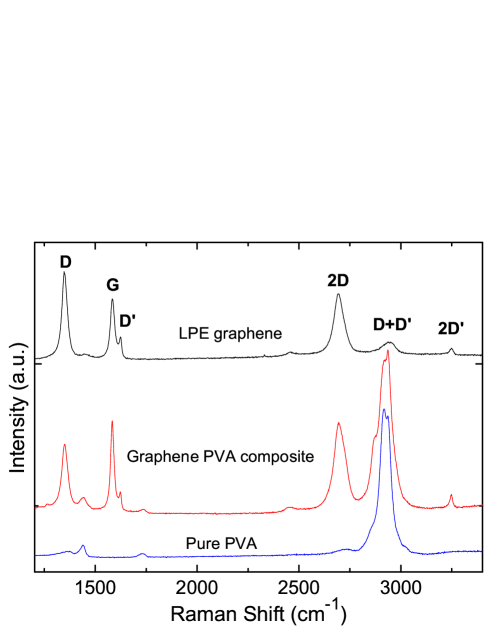
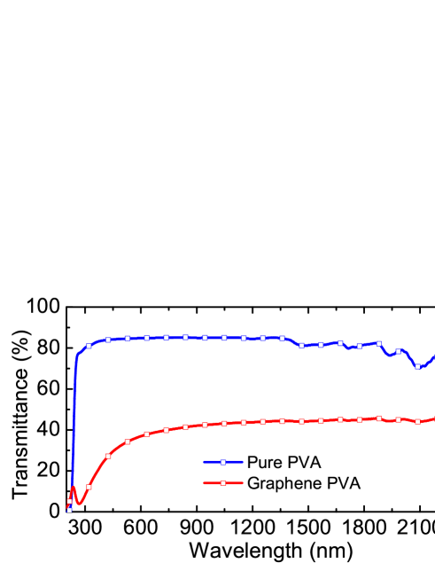
Fig.3 plots the transmittance of graphene-PVA compared to pure PVA. The UV peak in graphene-PVA is a signature of the van Hove singularity in the graphene density of stateskravetsprb10 . Strong UV absorption is also observed in pure PVAHaas_jpsp_1963 . By considering the pure PVA absorption, we can estimate that of the graphene component to be50% in the NIR. Given that a monolayer absorbs2.3%Nair_s_08 , we estimate that an average21 layers cross the light path.
The GSA is then prepared by sandwiching 2mm2 of the composite between two fiber connectors, adhered with index matching gel. The integrated device has4dB (60%) total insertion loss.
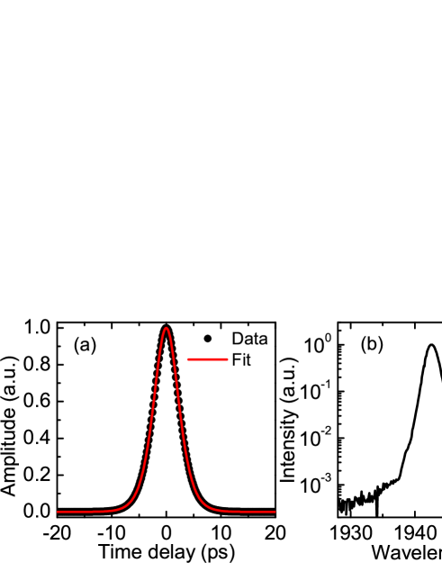
The autocorrelation of the output pulse, and the corresponding optical spectrum are plotted in Fig.4. Fig.4(a) shows that the pulse temporal profile is well represented by a sech2. The FWHM duration (after deconvolution) is 3.6ps. The corresponding FWHM spectral width is 2.1nm, giving a time-bandwidth product0.59, indicating low chirpAgrawal_book_app . The output power is2mW. Although the laser operates with negative cavity dispersion, and the pulses are soliton-like, the typical spectral sideband signature of deviation from average soliton operation is not observed, because the soliton length, given by , is long (, based on an estimated ps nm-1 km-1 at 1.94m) compared to cavity length (31), with the pulse duration and the group velocity dispersion.
The stability and quality of the generated pulses are evaluated via the radio frequency (RF) spectrumLinde:86 .
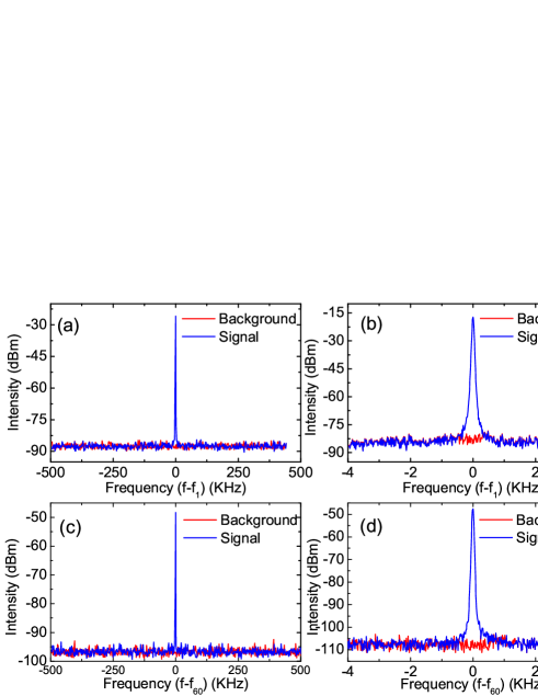
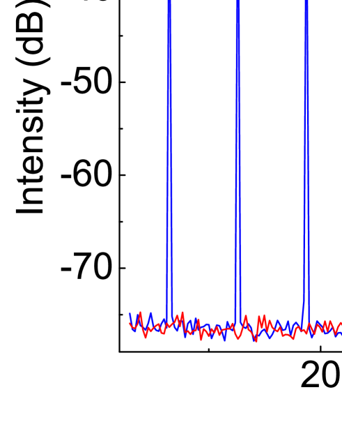
Fig.5 plots the fundamental and 60th harmonics over long (1MHz) and short (8kHz) frequency spans. The long range spectra indicate that the stability is high, with peak to noise-floor ratio limited by our 300Hz resolution (the noise floor of the analyzer is plotted in red). No sidebands at harmonic cavity frequencies are observed over the 1MHz span, suggesting good pulse-train stability and no Q-switching instabilities. This is confirmed by a spectral sweep over 100MHz, showing the first fifteen harmonics of the fundamental cavity frequency (Fig.6).
The short range spectra (Fig.5(b,d)), spanning 8kHz with 30Hz resolution, reveal a low level pedestal component70dB from the central spike. Following Ref.Linde:86, , we estimate the energy fluctuations, defined as output pulse energy change divided by average output energy, as , where is the power ratio between the central spike at and the peak of the noise band, (Hz) is the frequency width of the noise component, and (Hz) is the resolution bandwidth of the spectrum analyzer. With , and , give low pulse-to-pulse energy fluctuation .
Similarly, when the amplitude noise is low, the timing jitter can be evaluated asLinde:86 :, where is the cavity period, is the harmonic order. The low-frequency timing jitter (Fig.5(d)), evaluated at the 60th harmonic with , and , is estimated as . Given the long cavity period , this indicates a low timing jitter .
Our analysis suggests that, despite a very simple cavity consisting of non-polarization maintaining (PM) fiber, the laser emits high-quality pulses with low amplitude fluctuations () and low timing jitter. Although the laser mode-locks without the bandpass filter, the quality of the emitted pulses is compromised, with an increase in the RF spectrum noise.
In summary, we reported stable continuous-wave mode-locking of a Tm-doped fiber laser, using a graphene-based saturable absorber. The laser generates 3.6ps pulses at 6.46MHz, with0.4nJ pulse energy, demonstrating the operation of graphene in the mid-IR. This simple all-fiber design supports low noise operation in a small footprint, suitable for packing in a compact single-unit system. This can be realized using all-PM fiber components, which should further improve stability and noise propertiesLaegsgaard:08 .
We acknowledge funding from ERC grant NANOPOTS, EPSRC Doctoral Prize Fellowship, EPSRC grant EP/GO30480/1, EU Grants RODIN and GENIUS, a Royal Society Wolfson Research Merit Award, a RAEng Fellowship.
References
- (1) L. E. Nelson, E. P. Ippen, and H. A. Haus, Appl. Phys. Lett. 67, 19 (1995).
- (2) R. C. Sharp, D. E. Spock, N. Pan, and J. Elliot, Opt. Lett. 21, 881 (1996).
- (3) S. Kivisto, T. Hakulinen, M. Guina, and O. G. Okhotnikov, IEEE Photonics Technol. Lett. 19, 934 (2007).
- (4) M. A. Solodyankin, E. D. Obraztsova, A. S. Lobach, A. I. Chernov, A. V. Tausenev, V. I. Konov and E. M. Dianov, Opt. Lett. 33, 1336 (2008).
- (5) Q.Wang,J.Geng,T.Luo,S.Jiang,Opt. Lett.34,3616(2009)
- (6) W. Zeller, L. Naehle, P. Fuchs, F. Gerschuetz, L. Hildebrandt, and J. Koeth, Sensors 10, 2492 (2010)
- (7) B. M. Walsh, Laser Physics 19, 855 (2009)
- (8) M. Ebrahim-Zadeh,I.T.Sorokina, Mid-infrared Coherent Sources And Applications. (Springer, Dordrecht, 2008)
- (9) F. G. Gebhardt, Appl. Opt. 15, 1479 (1976)
- (10) M. E. Fermann and I. Hartl,IEEE J. Sel. Top. Quantum Electron. 15, 191 (2009).
- (11) O.Okhotnikov,A.Grudinin,M.Pessa,NewJ.Phys.6,177(2004)
- (12) U. Keller, Nature 424, 831 (2003).
- (13) Y.C. Chen, N. R. Raravikar, L. S. Schadler, P. M. Ajayan, Y.-P. Zhao, T.-M. Lu, G.-C. Wang, and X.-C. Zhang, Appl. Phys. Lett. 81, 975 (2002).
- (14) M. Breusing, C. Ropers, and T. Elsaesser,Phys. Rev. Lett. 102, 086809 (2009).
- (15) D. Brida, C. Manzoni, G. Cerullo, A. Tomadin, M. Polini, R. R. Nair, A. K. Geim, K. S. Novoselov, S. Milana, A. Lombardo, and A. C. Ferrari, (OSA, 2012), paper QTh3H.1.
- (16) F. Wang, A. G. Rozhin, V. Scardaci, Z. Sun, F. Hennrich, I. H. White, W. I. Milne, and A. C. Ferrari,Nat. Nanotechnol. 3, 738 (2008).
- (17) Z. Sun, D. Popa, T. Hasan, F. Torrisi, F. Wang, E. J. R. Kelleher, and A. C. Ferrari, Nano. Res. 3, 653 (2010).
- (18) D. Popa, Z. Sun, T. Hasan, F. Torrisi, F. Wang, A. C. Ferrari, Appl. Phys. Lett. 98, 073106 (2011).
- (19) T. Hasan, Z. Sun F. Wang, F. Bonaccorso, P. H. Tan, A. G. Rozhin,A.C.Ferrari Adv. Mater. 21,3874 (2009)
- (20) F. Bonaccorso, Z. Sun, T. Hasan and A. C. Ferrari, Nat. Photon. 4, 611 (2010).
- (21) Z. Sun T. Hasan, F. Torrisi, D. Popa, G. Privitera, F. Wang, F. Bonaccorso, D. M. Basko and A. C. Ferrari, ACS Nano 4, 803 (2010).
- (22) S. Y. Set, H. Yaguchi, Y. Tanaka, and M. Jablonski, IEEE J. Sel. Top. Quant. 10, 137 (2004).
- (23) V. Scardaci, Z. Sun, F. Wang, A. G. Rozhin, T. Hasan, F. Hennrich, I. H. White, W. I. Milne, and A. C. Ferrari,Adv. Mater. 20, 4040 (2008).
- (24) E. J. R. Kelleher, J. C. Travers, E. P. Ippen, A. C. Ferrari, S. V. Popov,J. R. Taylor,Opt. Lett. 34, 3526 (2009)
- (25) Z. Sun, A. G. Rozhin, F. Wang, I. H. White, F. Hennrich, and A. C. Ferrari,Appl. Phys. Lett. 93, 061114 (2008).
- (26) Z. Sun, A. G. Rozhin, F. Wang, D. Popa, W. O’Neill, and A. C. Ferrari,Appl. Phys. Lett. 95, 253102 (2009).
- (27) Z. Sun, T. Hasan, F. Wang, A. G. Rozhin, I. H. White, and A. C. Ferrari, Nano Res. 3, 404 (2010).
- (28) G. Della Valle, R. Osellame, G. Galzerano, N. Chiodo, G. Cerullo, P. Laporta, O. Svelto, A. G. Rozhin, V. Scardaci, A.C. Ferrari, Appl. Phys. Lett. 89, 231115 (2006).
- (29) S. J. Beecher, R. R. Thomson, N. D. Psaila,Z.Sun,T.Hasan,A.G. Rozhin, A.C.Ferrari, A.K.Kar, Appl. Phys. Lett. 97,111114 (2010)
- (30) T. R. Schibli, K. Minoshima, H. Kataura, E. Itoga, N. Minami, S. Kazaoui, K. Miyashita, M. Tokumoto, and Y. Sakakibara, Opt. Express 13, 8025 (2005).
- (31) A. Schmidt, S. Rivier, G. Steinmeyer, J. H. Yim, W. B. Cho, S. Lee, F. Rotermund, M. C. Pujol, M. Aguilo, F. Diaz, V. Petrov, U. Griebner, Opt. Lett. 33, 729 (2008)
- (32) P. A. Obraztsov, A. A. Sirotkin, E. D. Obraztsova, Y. P. Svirko, and S. V. Garnov, Opt. Rev. 17, 290 (2010).
- (33) Y. W. Song, S. Yamashita, C. S. Goh, S. Y. Set, Opt. Lett.32,430 (2007)
- (34) I. H. Baek, H. W. Lee, S. Bae, B. H. Hong, Y. H. Ahn, D.-I. Yeom, and F. Rotermund, Appl. Phys. Express 5, 032701 (2012).
- (35) W. D. Tan, C. Y. Su, R. J. Knize, G. Q. Xie, L. J. Li, and D. Y. Tang, Appl. Phys. Lett. 96, 031106 (2010).
- (36) W. B. Cho, J. H. Yim, S. Y. Choi, S. Lee, U. Griebner, V. Petrov, and F. Rotermund,Opt. Lett. 33, 2449 (2008).
- (37) D. Popa, Z. Sun, F. Torrisi, T. Hasan, F. Wang, and A. C. Ferrari, Appl. Phys. Lett. 97, 203106 (2010).
- (38) J. Liu, Y. G. Wang, Z. S. Qu, L. H. Zheng, L. B. Su, and J. Xu, Laser Phys. Lett. 9, 15 (2012).
- (39) J. Ma, G. Q. Xie, P. Lv, W. L. Gao, P. Yuan, L. J. Qian, H. H. Yu, H. J. Zhang, J. Y. Wang, and D. Y. Tang,Opt. Lett. 37, 2085 (2012).
- (40) S. Stankovich, D. A. Dikin, G. H. B. Dommett, K. M. Kohlhaas, E. J. Zimney, E. A. Stach, R. D. Piner, S. T. Nguyen, and R. S. Ruoff, Nature, 442, 282 (2006).
- (41) C. Mattevi, G. Eda, S. Agnoli, S. Miller, K. A. Mkhoyan, O. Celik, D. Mostrogiovanni, G. Granozzi, E. Garfunkel, and M. Chhowalla, Adv. Funct. Mater. 19, 2577 (2009).
- (42) X. Li, W. Cai, J. An, S. Kim, J. Nah, D. Yang, R. Piner, A. Velamakanni, I. Jung, E. Tutuc, S. K. Banerjee, L. Colombo, and R. S. Ruoff,Science 324, 1312 (2009).
- (43) K. S. Kim, Y. Zhao, H. Jang, S. Y. Lee, J. M. Kim, K. S. Kim, J.-H. Ahn, P. Kim, J.-Y. Choi, and B. H. Hong, Nature 457, 706 (2009).
- (44) Y. Hernandez, V. Nicolosi, M. Lotya, F. M. Blighe, Z. Sun, S. De, I. T. McGovern, B. Holland, M. Byrne, Y. K. Gun’Ko, J. J. Boland, P. Niraj, G. Duesberg, S. Krishnamurthy, R. Goodhue, J. Hutchison, V. Scardaci, A. C. Ferrari, and J. N. Coleman,Nature Nano. 3, 563 (2008)
- (45) S. Bae, Kim, H., Lee, Y., Xu, X., Park, J.-S., Zheng, Y., Balakrishnan, J., Lei, T., Ri Kim, H., Song, Y. I., Kim, Y.-J., Kim, K. S., Ozyilmaz, B., Ahn, J.-H., Hong, B. H. and Iijima, S., Nat Nano, 5, 574 (2010).
- (46) C. Berger, Song, Z., Li, T., Li, X., Ogbazghi, A. Y., Feng, R., Dai, Z., Marchenkov, A. N., Conrad, E. H., First, P. N. and de Heer, W. A., The Journal of Physical Chemistry B, 108, 19912 (2004).
- (47) P.W.Sutter,J.Flege,E.Sutter Nat Mater. 7, 406 (2008)
- (48) J. Wu, W. Pisula,K Müllen, Chem. Rev. 107, 718 (2007)
- (49) A. C. Ferrari, Meyer, J. C., Scardaci, V., Casiraghi, C., Lazzeri, M., Mauri, F., Piscanec, S., Jiang, D., Novoselov, K. S., Roth, S. and Geim, A. K., Phys. Rev. Lett., 97, 187401 (2006).
- (50) A.C.Ferrari,J.Robertson Phys. Rev.B 61,14095 (2000)
- (51) C. Casiraghi, A. Hartschuh, H. Qian, S. Piscanec, C. Georgi, A. Fasoli, K. S. Novoselov, D.M. Basko, A.C. Ferrari, A. C., Nano Lett, 9, 1433 (2009).
- (52) A.C.Ferrari,J.Robertson Phys. Rev.B 64, 075414 (2001)
- (53) L. G. Cancado, A. Jorio, E. H. M. Ferreira, F. Stavale, C. A. Achete,R.Capaz,M.Moutinho,A.Lombardo, T.S.Kulmala,A.C.Ferrari,Nano Lett.11,3190(2011)
- (54) S. Latil, V. Meunier, and L. Henrard,Phys. Rev. B 76, 201402 (2007).
- (55) V. G. Kravets, A. N. Grigorenko, R. R. Nair, P. Blake, S. Anissimova, K. S. Novoselov and A. K. Geim, Phys. Rev. B, 81, 155413 (2010).
- (56) H. C. Haas, H. Husek, and L. D. Taylor, J. Polym. Sci., Part A1, 1215 (1963).
- (57) R. R. Nair, P. Blake, A. N. Grigorenko, K. S. Novoselov, T. J. Booth, T. Stauber, N. M. R. Peres, and A. K. Geim,Science 320, 1308 (2008).
- (58) G. P. Agrawal, Applications of Nonlinear Fiber Optics. (Academic Press, London, 2001).
- (59) D. von der Linde, Appl. Phys. B 39, 201 (1986).
- (60) D.Turchinovich,X.Liu,J.Laegsgaard,Opt.Exp.16,14004(2008)