Slot-mode-coupled optomechanical crystals
Marcelo Davanço∗1,2, Jasper Chan2, Amir H. Safavi-Naeini2, Oskar Painter2, and Kartik Srinivasan1
1Center for Nanoscale Science and Technology, National Institute of Standards and Technology, Gaithersburg, MD
2Thomas J. Watson, Sr., Laboratory of Applied Physics, California Institute of Technology, Pasadena, CA 91125
∗Corresponding author: mdavanco@nist.gov
Abstract
We present a design methodology and analysis of a cavity optomechanical system in which a localized GHz frequency mechanical mode of a nanobeam resonator is evanescently coupled to a high quality factor () optical mode of a separate nanobeam optical cavity. Using separate nanobeams provides flexibility, enabling the independent design and optimization of the optics and mechanics of the system. In addition, the small gap (25 nm) between the two resonators gives rise to a slot mode effect that enables a large zero-point optomechanical coupling strength to be achieved, with kHz in a Si3N4 system at 980 nm and kHz in a Si system at 1550 nm. The fact that large coupling strengths to GHz mechanical oscillators can be achieved in is important, as this material has a broad optical transparency window, which allows operation throughout the visible and near-infrared. As an application of this platform, we consider wide-band optical frequency conversion between 1300 nm and 980 nm, using two optical nanobeam cavities coupled on either side to the breathing mode of a mechanical nanobeam resonator.
OCIS codes: 350.4238, 230.5298, 230.1040
References and links
- [1] T. J. Kippenberg and K. J. Vahala, “Cavity Opto-Mechanics,” Opt. Express 15, 17 172–17 205 (2007).
- [2] S. Weis, R. Rivière, S. Deléglise, E. Gavartin, O. Arcizet, A. Schliesser, and T. J. Kippenberg, “Optomechanically Induced Transparency,” Science 330, 1520– (2010).
- [3] A. H. Safavi-Naeini, T. P. M. Alegre, J. Chan, M. Eichenfield, M. Winger, Q. Lin, J. T. Hill, D. E. Chang, and O. Painter, “Electromagnetically induced transparency and slow light with optomechanics,” Nature (London) 472, 69–73 (2011).
- [4] J. D. Teufel, T. Donner, D. Li, J. W. Harlow, M. S. Allman, K. Cicak, A. J. Sirois, J. D. Whittaker, K. W. Lehnert, and R. W. Simmonds, “Sideband cooling of micromechanical motion to the quantum ground state,” Nature (London) 475, 359–363 (2011).
- [5] J. Chan, T. P. M. Alegre, A. H. Safavi-Naeini, J. T. Hill, A. Krause, S. Gröblacher, M. Aspelmeyer, and O. Painter, “Laser cooling of a nanomechanical oscillator into its quantum ground state,” Nature (London) 478, 89–92 (2011).
- [6] A. H. Safavi-Naeini and O. Painter, “Proposal for an optomechanical traveling wave phonon-photon translator,” New Journal of Physics 13, 013 017 (2011).
- [7] L. Tian and H. Wang, “Optical wavelength conversion of quantum states with optomechanics,” Phys. Rev. A 82, 053 806 (2010).
- [8] D. E. Chang, A. H. Safavi-Naeini, M. Hafezi, and O. Painter, “Slowing and stopping light using an optomechanical crystal array,” New Journal of Physics 13, 023 003 (2011).
- [9] K. Stannigel, P. Rabl, A. S. Sørensen, M. D. Lukin, and P. Zoller, “Optomechanical transducers for quantum-information processing,” Phys. Rev. A 84, 042 341 (2011).
- [10] M. Ludwig, A. H. Safavi-Naeini, O. Painter, and F. Marquadt, “Optomechanical photon detection and enhanced dispersive phonon readout,” arXiv:1202.0532 (2012).
- [11] M. Eichenfield, J. Chan, R. M. Camacho, K. J. Vahala, and O. Painter, “Optomechanical crystals,” Nature 462, 78–82 (2009).
- [12] J. T. Hill, A. H. Safavi-Naeini, J. Chan, and O. Painter, “Coherent optical wavelength conversion via cavity-optomechanics,” arXiv:1203.5730 (2012).
- [13] F.-V. K. M. C. Dong, C. and W.-H. Tian, L., “A microchip optomechanical accelerometer,” arXiv:1205.2360 (2012).
- [14] V. R. Almeida, Q. Xu, C. A. Barrios, and M. Lipson, “Guiding and confining light in void nanostructure,” Opt. Lett. 29, 1209–1211 (2004).
- [15] M. Eichenfield, R. Camacho, J. Chan, K. J. Vahala, and O. Painter, “A picogram- and nanometre-scale photonic-crystal optomechanical cavity,” Nature 459, 550–555 (2009).
- [16] Y.-G. Roh, T. Tanabe, A. Shinya, H. Taniyama, E. Kuramochi, S. Matsuo, T. Sato, and M. Notomi, “Strong optomechanical interaction in a bilayer photonic crystal,” Phys. Rev. B 81, 121 101 (2010).
- [17] Q. Lin, J. Rosenberg, X. Jiang, K. J. Vahala, and O. Painter, “Mechanical Oscillation and Cooling Actuated by the Optical Gradient Force,” Phys. Rev. Lett. 103, 103 601 (2009).
- [18] G. S. Wiederhecker, L. Chen, A. Gondarenko, and M. Lipson, “Controlling photonic structures using optical forces,” Nature 462, 633–636 (2009).
- [19] A. H. Safavi-Naeini, T. P. M. Alegre, M. Winger, and O. Painter, “Optomechanics in an ultrahigh-Q two-dimensional photonic crystal cavity,” Applied Physics Letters 97, 181 106 (2010).
- [20] P. E. Barclay, K. Srinivasan, O. Painter, B. Lev, and H. Mabuchi, “Integration of fiber-coupled high- SiNx microdisks with magnetostatic atom chips,” Appl. Phys. Lett. 89, 131 108 (2006).
- [21] A. Gondarenko, J. S. Levy, and M. Lipson, “High confinement micron-scale silicon nitride high Q ring resonator,” Optics Express 17, 11 366 (2009).
- [22] E. Shah Hosseini, S. Yegnanarayanan, A. H. Atabaki, M. Soltani, and A. Adibi, “High quality planar silicon nitride microdisk resonators for integrated photonics in the vsible wavelength range,” Optics Express 17, 14 543 (2009).
- [23] B. M. Zwickl, W. E. Shanks, A. M. Jayich, C. Yang, A. C. Bleszynski Jayich, J. D. Thompson, and J. G. E. Harris, “High quality mechanical and optical properties of commercial silicon nitride membranes,” Applied Physics Letters 92, 103 125 (2008).
- [24] S. S. Verbridge, H. G. Craighead, and J. M. Parpia, “A megahertz nanomechanical resonator with room temperature quality factor over a million,” Applied Physics Letters 92, 013 112 (2008).
- [25] K. Y. Fong, W. H. P. Pernice, M. Li, and H. X. Tang, “High Q optomechanical resonators in silicon nitride nanophotonic circuits,” Applied Physics Letters 97, 073 112 (2010).
- [26] A. G. Krause, M. Winger, T. D. Blasius, Q. Lin, and O. Painter, “A microchip optomechanical accelerometer,” arXiv:1203.5730 (2012).
- [27] P. E. Barclay, K. Srinivasan, and O. Painter, “Nonlinear response of silicon photonic crystal microcavities excited via an integrated waveguide and fiber taper,” Opt. Express 13, 801–820 (2005).
-
[28]
Q. Quan and M. Loncar, “Deterministic design of wavelength
scale,
ultra-high Q photonic crystal nanobeam cavities,” Opt. Express 19,
18 529–18 542 (2011).
http://www.opticsexpress.org/abstract.cfm?URI=oe-19-19-18529 - [29] Q. Quan, P. B. Deotare, and M. Loncar, “Photonic crystal nanobeam cavity strongly coupled to the feeding waveguide,” Applied Physics Letters 96, 203 102 (2010).
-
[30]
M. Eichenfield, J. Chan, A. H. Safavi-Naeini, K. J. Vahala, and
O. Painter,
“Modeling dispersive coupling andlosses of localized optical
andmechanical modes in optomechanicalcrystals,” Opt. Express 17,
20 078–20 098 (2009).
http://www.opticsexpress.org/abstract.cfm?URI=oe-17-22-20078 - [31] S. G. Johnson, M. Ibanescu, M. A. Skorobogatiy, O. Weisberg, J. D. Joannopoulos, and Y. Fink, “Perturbation theory for Maxwell’s equations with shifting material boundaries,” Phys. Rev. E 65, 066 611 (2002).
- [32] J. Chan, A. H. Safavi-Naeini, J. Hill, S. Meenehan, and O. Painter, “Optimized optomechanical crystal cavity with acoustic radiation shield,” (2012), arXiv:1206.2099.
- [33] P. T. Rakich, C. Reinke, R. Camacho, P. Davids, and Z. Wang, “Giant Enhancement of Stimulated Brillouin Scattering in the Subwavelength Limit,” Phys. Rev. X 2, 011 008 (2012).
- [34] M. Khan, T. Babinec, M. W. McCutcheon, P. Deotare, and M. Lončar, “Fabrication and characterization of high-quality-factor silicon nitride nanobeam cavities,” Opt. Lett. 36, 421–423 (2011).
- [35] A. J. Shields, “Semiconductor quantum light sources,” Nature Photonics 1, 215–223 (2007).
- [36] R. H. Hadfield, “Single-photon detectors for optical quantum information applications,” Nature Photonics 3, 696–705 (2009).
-
[37]
A. H. Safavi-Naeini and O. Painter, “Design of
optomechanical cavities
and waveguides on a simultaneous bandgap phononic-photonic crystal slab,”
Opt. Express 18, 14 926–14 943 (2010).
http://www.opticsexpress.org/abstract.cfm?URI=oe-18-14-14926 -
[38]
R. M. Camacho, J. Chan, M. Eichenfield, and O. Painter,
“Characterization of radiation pressure and thermal effects in a
nanoscale optomechanical cavity,” Opt. Express 17, 15 726–15 735
(2009).
http://www.opticsexpress.org/abstract.cfm?URI=oe-17-18-15726 - [39] H. J. Kimble, “The quantum internet,” Nature (London) 453, 1023–1030 (2008).
- [40] M. T. Rakher, L. Ma, O. Slattery, X. Tang, and K. Srinivasan, “Quantum transduction of telecommunications-band single photons from a quantum dot by frequency upconversion,” Nature Photonics 4, 786–791 (2010).
- [41] J. Hwang, M. Pototschnig, R. Lettow, G. Zumofen, A. Renn, S. Goetzinger, and V. Sandoghdar, “A single-molecule optical transistor,” Nature 460, 76–80 (2009).
- [42] C. A. Regal, J. D. Teufel, and K. W. Lehnert, “Measuring nanomechanical motion with a microwave cavity interferometer,” Nature Physics 4, 555–560 (2008).
- [43] J. Sulkko, M. A. Sillanpää, P. Häkkinen, L. Lechner, M. Helle, A. Fefferman, J. Parpia, and P. J. Hakonen, “Strong Gate Coupling of High-Q Nanomechanical Resonators,” Nano Letters 10, 4884–4889 (2010).
- [44] F. Massel, T. T. Heikkilä, J.-M. Pirkkalainen, S. U. Cho, H. Saloniemi, P. J. Hakonen, and M. A. Sillanpää, “Microwave amplification with nanomechanical resonators,” Nature (London) 480, 351–354 (2011).
1 Introduction
Recent experiments using radiation pressure effects in cavity optomechanical systems [1], such as electromagnetically-induced transparency [2, 3] and ground state cooling [4, 5], as well as theoretical proposals for using such optomechanical systems in quantum information processing applications [6, 7, 8, 9, 10], generally rely upon the achievement of large zero-point optomechanical coupling rates and low optical and mechanical dissipation rates. They also typically require operation in the resolved sideband limit in which the mechanical resonance frequency must exceed the optical dissipation rate. One-dimensional optomechanical crystals [11, 3, 8], in which a periodic patterning is applied to a doubly clamped nanobeam in order to simultaneously localize GHz phonons and near-infrared (200 THz) photons, are one promising architecture for future work in quantum cavity optomechanics.
While the use of a single nanobeam in such work has many advantages, separation of the optical cavity and mechanical resonator can afford greater levels of flexibility. This can be useful in applications in which multiple optical modes are coupled to the same mechanical resonance, for example, to achieve wavelength conversion [6, 7, 12, 13] or in converting traveling wave phonons to traveling wave photons [6]. One disadvantage of separating the mechanical resonator and optical cavity is that the optomechanical coupling rate generally tends to be smaller, given the reduced overlap between the mechanical and optical modes. To overcome this, one can focus on optical modes formed within the gap between the optical and mechanical resonator. Such air-slot type modes [14], which display a high electric field concentration in the air gap, have been used to achieve large optomechanical couplings [15, 16, 17, 18], and sub-wavelength effective optomechanical lengths [19]. In these demonstrations, however, the mechanical resonators and optical cavities were not separated, and mechanical resonance frequencies were typically MHz. For operation in the resolved sideband regime, higher frequencies are desirable, given that high- cavities in materials like Si and typically have optical dissipation rates that are MHz.
Here, we present the design of a cavity optomechanical system in which a GHz frequency localized mode in a mechanical nanobeam resonator is coupled to a localized 300 THz optical mode in a separate optical nanobeam resonator (Fig. 1). We show that the slot mode effect can increase optomechanical coupling rates with respect to those found in a single nanobeam optomechanical system, and consider applications of this approach to instances in which the separated mechanical and optical resonators are particularly advantageous, such as wide-band optical wavelength conversion [6]. We consider both and Si systems, although our primary focus is on . In particular, the system has many potential advantages for applications in quantum cavity optomechanics: optical has been demonstrated over a wide range of wavelengths in the visible and near-infrared in [20, 21, 22]. This can allow compatibility with quantum systems based on trapped atoms, ions, and semiconductor quantum dots, whose relevant optical transitions are often below 1000 nm (where Si is opaque). Furthermore, these stoichiometric Si3N4 films under tensile stress have been shown to support high mechanical quality factors (), both in commercial thin films [23] and in nanofabricated devices [24, 25, 26]. Finally, as Si3N4 does not exhibit the two-photon absorption and subsequent free-carrier absorption and dispersion that silicon does [27], higher optical powers are usable in this system, potentially increasing the range of pump-enhanced optomechanical coupling values that can be achieved. Our geometry is predicted to support GHz mechanical frequencies, optical , and a zero-point optomechanical coupling strength kHz. Such values should in principle enable strong radiation pressure driven phenomena.
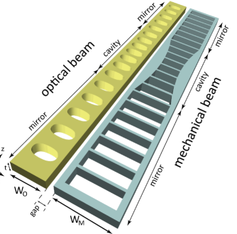
The proposed geometry, shown in Fig. 1, consists of two suspended parallel dielectric beams of refractive index , widths and and thickness , separated by a gap of width . Both beams are etched through to form quasi-periodic 1D structures in the -direction. The ”optical” beam’s 1D lattice is modulated so that a quasi-TE ( across the center of the layer at ) confined optical mode is supported at an optical frequency . Optical confinement along the beam is provided by a 1D photonic bandgap, while total internal reflection provides confinement in the and directions [11, 28, 29]. With a sufficiently small spacing , the quasi-TE mode consists of an air-gap resonance as in [14], with a strongly concentrated, almost completely -oriented electric field between the two beams. The ”mechanical” beam is designed to support a mechanical resonance of frequency , confined in , that displaces the boundary facing the optical resonator, thereby closing the gap and thus shifting the optical resonance frequency . It is important to stress that the optical cavity is actually formed by the ”optical” beam and the ”mechanical” beam’s closest arm (indicated in Fig. 1), so that optical resonances depend strongly on the gap width. Nevertheless, optical and mechanical resonances can be tuned with great independence, as we show in the following sections. Sections 2 and 3 present background information on the simulations performed and consider the case of a single Si3N4 nanobeam optomechanical cavity, as a baseline reference. Section 4 describes the design of the slot-mode-coupled optical and mechanical nanobeam resonators, emphasizing the design approach for achieving high- optical modes, GHz mechanical modes, and large optomechanical coupling. Finally, section 5 considers a few applications of this platform.
2 Background
The shift in the frequency of a particular optical resonance due to displacement of the nanostructure boundaries produced by a mechanical resonance at frequency is quantified by the optomechanical coupling ; here, is the cavity boundary displacement, and is an effective optomechanical interaction length [30]. The effective length can be estimated via the perturbative expression [31]
| (1) |
Here, and are the modal electric and electric displacement fields, respectively, , , and are the permittivities of the nanobeam material and air. The mass displacement due to the mechanical resonance is given by , and the normal surface displacement at the structure boundaries is , where is the surface normal. The integral in the denominator is performed over the entire surface of the nanostructure.
The optomechanical coupling can be converted into a pure coupling rate between the optical and mechanical resonances: , where is the zero point fluctuation amplitude for mechanical displacement [6] and is the motional mass of the mechanical resonance at frequency . The motional mass can be obtained from the displacement and the nanobeam material density by .
We point out that eq.(1) only quantifies frequency changes due to boundary distortions. An additional, potentially important contribution to the optomechanical coupling comes from the photo-elastic effect, which corresponds to local, stress-induced changes of the refractive index. This contribution can be quite significant, and was in fact recently been exploited to demonstrate, in combination with the moving-boundary contribution, optomechanical coupling rates in excess of MHz in silicon nanobeam optomechanical crystals [32]. Giant enhancement of Brillouin scattering in suspended silicon waveguides, resulting from both photo-elastic and radiation pressure optomechanical coupling, has also been predicted [33]. In the present work, only moving-boundary contributions were taken into account.
Optical and mechanical resonator modes are obtained using the finite element method, as described in [15], and are used in the expressions above to yield the optomechanical coupling rates.
3 nanobeam
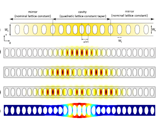
To gain some initial insight into the optomechanical rates achievable with a low index contrast nanobeam with ’standard’ (i.e., single nanobeam) geometry, we start by investigating an optical cavity composed of a 1D array of air holes etched on a nanobeam, as show in Fig. 2(a) [34]. We seek to achieve the largest possible optomechanical coupling rate and optomechanical coupling, . Our cavity was designed to support the optical mode at a wavelength nm shown in Fig. 2(b). The 980 nm wavelength band is technologically important due to the availability of triggered single photon sources based on InAs quantum dots [35] and silicon based single photon detectors which operate within this range [36]. Together with the optical mode, this cavity supports confined mechanical modes co-located with the optical resonance. The fundamental breathing mechanical mode (FBM) at GHz, shown in Fig. 2(e), with motional mass fg, displays the highest optomechanical coupling rate to the optical resonance in Fig. 2(b).
To reach this design, the procedure outlined in Section 4.1 was initially employed to obtain a high optical mode. The resulting cavity displayed a quadratic variation of the lattice constant (the spacing between holes) from the center to the edges [28], and supported, together with the optical mode, a localized breathing mechanical mode. The cavity geometry was then optimized via a nonlinear minimization code to yield a maximized optomechanical coupling rate kHz (), while maintaining a high optical quality factor . The optimization was realized by allowing the aspect ratio of the elliptical holes (vertical axis over horizontal axis) to vary quadratically from the cavity center, then searching a 2D space of aspect ratios at the center and at the edge of the cavity. Reducing the aspect ratio at the cavity center proved to be beneficial in reducing the effective length , by reducing the mechanical mode volume and promoting better overlap between the optical and mechanical modes. The factor was not strongly affected, most likely because the hole areas were maintained.
The nanobeam also supports two additional high order modes, shown in Figs. 2(c) and (d), at wavelengths nm and nm, both with , which couple to the mechanical mode in Fig. 2(e) with kHz and kHz, respectively.
Wavelength conversion
A cavity optomechanical system supporting two optical resonances at different wavelengths and a shared mechanical resonance may be used for performing wavelength conversion of classical or quantum optical signals [6, 7, 12, 13]. In this photon-phonon translator scheme, a signal tuned to one of the optical resonances is transduced to the shared mechanical resonance, and from the latter to a second optical resonance at a different wavelength. These conditions are achieved in the single nanobeam design above, where the three displayed optical resonances couple to the breathing mechanical mode. The wavelength separation between input and converted signals is nm, given by the separation between the fundamental and third order optical modes. Wider separations can in principle be achieved in larger cavities, however, given the requirement of small optical and mechanical modal volumes for increased optomechanical coupling, is expected to drop [37]. Ultimately, the achievable spectral separation in single nanobeam designs has an upper bound given by the achievable photonic bandgap width, which increases with the refractive index contrast. Nanobeams based on , with refractive indices , are considerably more limited than Si nanobeams (.
4 Slot mode nanobeams
4.1 Optical cavity design
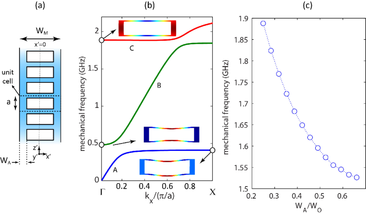
We start the design of a optical cavity for operation in the 980 nm band by considering the geometry in Fig. 3(a). This is a version of the geometry in Fig. 1 in which the mechanical resonator is stripped of its rightmost arm and connecting ribs (in what follows, we refer to the remaining arm of the mechanical resonator as the ’optical arm’). We first generate Bloch bands for photonic crystals with unit cells as highlighted in Fig. 3(a), with optical arm widths constant in . As seen in Fig. 3(b), the fundamental TE Bloch band displays bandgaps at the -point (bands for and are displayed), and no overlapping bands below the light-line in the spectral region near the lowest band-edge. Figure 3(c) shows the squared electric field amplitude for the Bloch modes at the Brillouin zone boundary, for the structure with
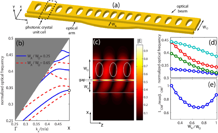
Figure 3(d) shows the evolution of the first four TE bands at the -point as a function of . The apparent reduction in bandgap (i.e., between the first and second bands) width with increasing is due to an effective decrease in the filling fraction, or the ratio between air and dielectric regions in the unit cell. The larger bandgaps achieved with smaller correspond to a large effective reflectivity and thus are better suited for strong spatial confinement. On the other hand, a wider is desirable for enhanced modal frequency shifts with gap width (i.e., optomechanical coupling). This is evident in Fig. 3(e), where is plotted, assuming in eq. (1), for the fundamental TE photonic crystal modes at the -point, as a function of the ratio. A minimized optomechanical length can be obtained for , about lower than the maximum value within the plotted range. A trade-off between spatial confinement and optomechanical coupling must thus be achieved in a geometry where the mechanical beam width is gradually reduced away from the cavity center, until a ’nominal’ width is reached, for which the reflectivity is highest. We thus choose to let vary from at the cavity center to at the mirrors.
The photonic bands shown in Fig. 1(a) were obtained with , , and ( and are the elliptical holes’ axes in the and directions, is the thickness), parameters that led to a large bandgap for . We choose the thickness to be nm and the gap to be nm, and determine the remaining dimensions by regarding the cavity center, where . A zero-finding routine was used to determine the width and the corresponding cavity lattice constant for the lowest -point TE Bloch mode to be at a wavelength nm. We point out that while such small gap width poses a great fabrication challenge, it may in principle be achieved as in [38], where the GPa Si3N4 film stress was harnessed to bring two nanobeams together as closely as 40 nm.
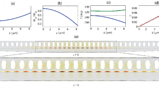
To produce an effective potential well for the fundamental TE mode at the -point, the band edge must shift towards lower frequencies at increasing distances from the cavity center. This shift is opposite to what is obtained when is modulated in the desired way, and thus we choose to modulate the lattice constant along the cavity in order to produce the correct trend. Following the procedure described in [28], allowing both beam width and the lattice constant to vary quadratically away from the cavity center (Figs. 4(a) and (b)), the desired trend for the lowest band edge is achieved (Fig. 4(c)), and an approximately linear mirror strength (Fig. 4(d)). The mirror strength corresponds to the imaginary part of the Bloch wavenumber for bandgap frequencies at the X-point, . From 1D first order perturbation theory,
| (2) |
where are the dielectric and air band edges at the Brillouin zone boundary, and is the midgap frequency. Linear mirror strength profiles tend to produce optical modes with reduced spatial harmonics above the light line. This leads to reduced power leakage into the air, and thus higher quality factors [28]. We point out that the quadratic lattice constant and beam width tapers employed here, though not optimal, produce sufficiently linear mirror strength profiles for high quality factors to be achieved.
4.2 Mechanical resonator design
The optical resonator design dictates the geometry of the mechanical beam’s optical arm. The remaining parts of the mechanical resonator (Fig. 1) are designed around this constraint. While the secondary arm can in principle be chosen arbitrarily, for simplicity we let it be identical to the optical arm. The lattice formed by the connecting ribs are made to follow the optical lattice. This configuration minimized deterioration of the optical quality factor due to scattering at the ribs. Rib widths seemed to have a strong effect on scattering, and had to be made small ( nm) to produce sufficiently low degradation.
The mechanical resonator geometry studied here is similar to the optomechanical nanobeam crystal analyzed in [30]. While in this reference a detailed account of the phononic crystal mechanical band structure is provided, here we focus only on the relevant mechanical bands for enhanced optomechanical coupling. We are interested in producing ’breathing’ mechanical modes which displace the nanobeam arms laterally, allowing the air gap width to change.
Phononic bands for the crystal shown in Fig. 5(a) are plotted in Fig. 5(b), for an arm width . Bands A, B and C were obtained with symmetric boundary conditions for the displacement at the , and planes, so that no modes with other symmetries are displayed. We refer to ref. [30] for a more detailed account of the additional existing bands. The characteristic boundary displacements for each band are inset in Fig. 5(b). Near the -point, the mechanical modes of band C display the desired lateral displacement pattern, necessary for the formation of breathing resonances.
Modes from bands A and B stem from flexural modes of the connecting ribs - evident in the inset displacement plots- and display negligible lateral displacement. Band C has a minimum at , which creates the conditions for the formation of a breathing mode phononic resonance. Indeed, a phononic cavity naturally arises from the quadratic spatial arm width () variation, as evidenced in Fig. 5(c), where the -point edge of band C is plotted as a function of . As the arm width decreases from the cavity center towards the mirror regions, the band edge moves towards higher frequencies, placing the resonance frequency within the breathing mode phononic bandgap. Localized breathing modes as plotted in Figs. 6(a) and (b) result, with frequencies that decrease with increasing nanobeam widths , as shown in Fig. 6(c). It is also apparent that displacement profiles can also change considerably with . This is quantified in Fig. 6(d), where the normalized displacement
| (3) |
is plotted as a function of . The integral is performed over the optical arm’s surface facing the optical beam, and so is a measure of the uniformity of the optical arm’s displacement towards the optical beam. The evolution of the modal displacement pattern also results in a variation of the motional mass, as shown in Fig. 6(e)
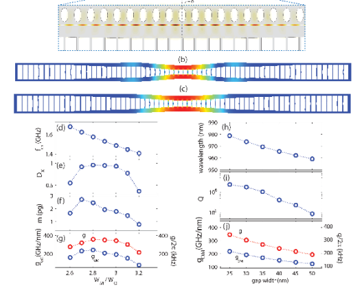
Optomechanical coupling
The optomechanical coupling and coupling rate between the optical resonance calculated in Section 4.1 and the breathing mode mechanical resonances discussed in Section 4.2 are plotted in Fig. 6(f), as a function of . The maximum and values achieved for the range shown are the value obtained with the optimized single nanobeam of Section 3, despite the larger motional masses (Fig. 6(e)). The strong influence of the gap width on the optomechanical coupling is evident in the fact that both and approximately follow the trend of . In fact, the effect of increasing gap widths on the resonance wavelength is plotted in Fig. 6(g), displaying a fast blue shift for decreasing gaps. Because the cavity was initially designed to have a 25 nm gap, the quality factor decreases as this parameter is changed, and so do the optomechanical coupling and the coupling rate , despite the increase in the optical frequency (, is the zero point fluctuation amplitude for mechanical displacement). For any fixed gap width, however, the hole lattice can be adjusted to yield a high quality factor. For instance, changing the the lattice constant profile in Fig. 4(a) so it varies (quadratically) from 325 nm at to 365 nm at the cavity edge gives an optical mode at wavelength nm with and GHz/nm. In contrast, for the 25 nm gap design of Fig. 6, a 40 nm gap yields nm, and GHz/nm. This serves to show that our double nanobeam design affords great flexibility towards optimized performance under constraints such as resonance wavelength, quality factor or gap width.
4.3 Effect of index contrast
Equation 1 suggests that the higher index contrasts generally yield higher optomechanical coupling. In addition, the electric field concentration in the slot region ( [14]) is expected to add a significant contribution to and . Indeed, a design for operation at the 1550 nm band based on silicon (), produced with the same procedure as above, yielded an optomechanical coupling rate kHz for a mechanical resonance at GHz (an optimized single nanobeam design with similar geometrical parameters displayed kHz for a mechanical resonance at GHz). Table 1 shows the relevant optomechanical quantities for this design. Here, the 1D lattice constant was allowed to vary quadratically from 360 nm to 385 nm, and the optical beam width varied between from 325 nm at the cavity center to 150 nm.
(nm) (GHz) (GHz/nm) (kHz) () m (pg) 1540.4 1.38 485 882 0.4 1.8
5 Applications
5.1 Wide spectral separation wavelength conversion
While a ’standard’ nanobeam geometry such as that studied in Section 3 already offers the necessary conditions for wavelength conversion, the spectral separation between optical resonances of different orders is limited to, at best, 70 nm. Even in silicon nanobeam designs, where the higher index contrast leads to a considerably wider spacing between resonances, a maximum separation of nm is achievable [12]. As discussed in Section 3, the achievable wavelength separation in the single nanobeam design is ultimately given by the nanobeam photonic bandgap, which can be limited even for high contrasts such as in the Si case. The ability to perform wavelength conversion over considerably wider wavelength separations may be desirable for applications in which classical or quantum information transmitted over optical fibers at telecom wavelengths is originally produced at completely separate wavelength bands, for instance in the near-infrared or visible range. Such an achievement would be enabling for proposed hybrid quantum optical networks, whose nodes may be widely different from each other (trapped atoms [39], quantum dots[40], organic molecules [41], etc).
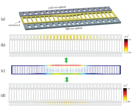
The physical separation between optical and mechanical resonances afforded through our double nanobeam optomechanical approach allows the formation of optomechanical resonators with widely spaced, spatially separate and semi-independent optical resonances with reasonable optomechanical coupling to the same mechanical resonance. Such a resonator, schematically depicted in Fig. 7(a), consists of a central mechanical nanobeam laterally sandwiched by two optical nanobeams. Air gaps on the two sides of the mechanical resonator allow a single breathing mode resonance to couple efficiently to optical nanoslot modes on both sides. We demonstrate the feasibility of this scheme via an example in which optical resonances at wavelengths of 980 nm and 1310 nm are supported. Figures 7(b) and (d) respectively show the 1310 nm and 980 nm resonances of a double nanobeam resonator that share the mechanical resonance at GHz in Fig. 7(c). Both optical resonances display quality factors in excess of , which allows operation in the resolved sideband regime. The 980 nm wavelength optical cavity has exactly the same geometry parameters as that in Section 4.1. The 1310 nm cavity was designed with the same procedure as described in Section 4.1. Achieving high optical quality factors for both cavities required significant modifications to the original mechanical nanobeam geometry presented in Section 4.2. First, the nanobeam width had to be increased to , to minimize the interaction between the two optical resonators. This resulted in a lower resonance frequency, GHz. In addition, the 1310 nm resonator’s optical arm was made constant with , to prevent coupling of the confined 980 nm resonance to leaky resonances of the 1310 nm beam. This caused the optomechanical coupling for the 1310 nm resonator to be lower than that obtained with modulation of the optical arm ( GHz/nm). It is worth noting on the other hand that, despite the uniform arm width, can still be reasonably high. This parameter, together with the optomechanical coupling rate , effective optomechanical length and motional mass for the two resonators are given in Table 2.
(nm) (GHz/nm) (kHz) () m (pg) 978 179 322 1.7 1.92 1318 67 122 3.4 1.85
As discussed in the Appendix, the conversion efficiency achievable in the scheme proposed in ref. [6] and demonstrated in ref. [12] depends on the cooperativities of optical cavities 1 and 2 ( is the average photon population in each cavity), and unity conversion requires . The coupling rates calculated above are approximately a factor of three times smaller than those used in ref. [12]. These smaller coupling rates can be compensated by increasing the number of photons in the cavity (by a factor of nine, assuming similar optical and mechanical decay rates are achievable), which should be feasible in the Si3N4 system. We also note that the disparate coupling rates for the two cavities is not expected to influence the ability to achieve high efficiencies, as such differences may be compensated by proper balancing of the intra-cavity photon populations .
5.2 Strong optomechanical coupling
The observation of quantum behavior in cavity optomechanics relies on the possibility of strong coupling between optical and mechanical resonances. Ultimately, a regime is sought in which interactions at the single photon and phonon levels are observable. This single-photon strong coupling regime, in which a single phonon is able to shift an optical resonance by an extent comparable to the latter’s linewidth, is characterized by a coupling rate comparable to both the optical resonance decay rate and the mechanical frequency . Achieving single photon strong coupling at optical frequencies is challenging due to high optical losses. In [10], a scheme was proposed for producing a strongly enhanced, effective optomechanical coupling for quantum non-demolition (QND) photon detection and phonon number readout measurements. Such a QND measurement would extract information from the quantum system without disturbing its quantum state. In the setup of [10], an optomechanical crystal geometry supports two optical resonances split by a frequency , comparable to the mechanical frequency of an interacting mechanical resonance. The coherent interaction between photons and phonons is characterized by an effective coupling rate , where and is the bare optomechanical coupling rate. In the limit , the optical frequency shift is , where is the phonon number,which may be sufficiently large to produce a phonon number readout.
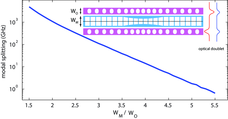
The flexibility of our double nanobeam geometry allows us to accommodate the optical mode splittings required in the scheme proposed in [10]. As shown in the inset of Fig. 8, an optomechanical resonator is formed by two identical optical beams sandwiching a mechanical resonator. The two individual optical resonances couple evanescently, forming a symmetric / anti-symmetric doublet whose spectral separation can be controlled by the mechanical beam width . The modal splitting , shown in Fig. 8 for the same cavity parameters as in Section 3, indeed decreases with increasing , as the spatial overlap between the individual optical resonances diminishes. The main breathing mode mechanical frequency also decreases with , however remaining within the GHz range even for the largest mechanical beam widths plotted, so that the regime can be achieved. The coupling between the two modes can also be tuned by creating optical cavities with coinciding individual resonances, but different gap widths.
.
5.3 Microwave to optical photon conversion
State-of-the art superconducting microwave circuits can be designed to provide controllable, coherent interactions between superconducting qubits and high quality microwave cavity resonators, and provide favorable conditions for the creation and manipulation of photonic states at microwave frequencies. In the context of a quantum network [39] where the nodes are connected via photonic links, however, low loss transmission of microwave photons over long distances becomes a challenge, as superconducting transmission lines would be required. The ability to convert between microwave and optical photons which can be transmitted via optical fibers thus constitutes an appealing solution to this problem.
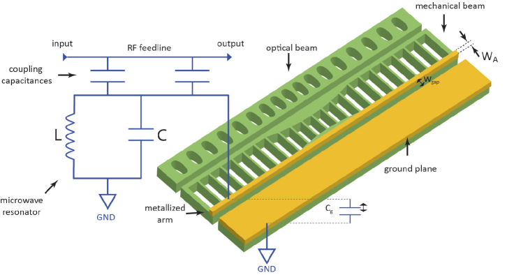
The physical separation between optical and mechanical resonances in our geometry creates opportunities for the generation of microwave-to-optical frequency signal transducers. One possible geometry is illustrated in Fig. 9, where the far arm of the mechanical resonator incorporates a metallic strip, and, together with a neighboring ground plane, forms a capacitor that integrates a superconducting, planar circuit microwave resonator, similar to that demonstrated in [42, 43]. The displacement of the mechanical beam affects the cavity resonance by causing a variation in the circuit capacitance. Coupling between the mechanical displacement and cavity capacitance is stronger for smaller gaps between the metallized beam and the ground plane. At the same time, the distance between the metallized mechanical beam arm and the optical resonator must be sufficient to prevent significant deterioration of the quality factor of the optical cavity, while keeping the superconducting microwave resonator sufficiently separated from strong optical fields is necessary to avoid heating and degradation of its performance. As shown in Section 3, this separation can be accomplished through increased mechanical beam widths. While this leads to decreasing mechanical frequencies for the fundamental breathing mode, as seen in the previous sections, mechanical frequencies in the GHz range are achievable.
As is the case with optical-to-optical conversion, microwave-to-optical conversion under the protocol described in ref. [6] requires , that is, the cooperativity of the microwave and optical resonators (see Appendix) should be large and matched to each other. We anticipate that the design of the optical resonator will be similar to that described previously, while a full design of the microwave cavity is beyond the scope of this paper. Qualitatively, we note the conceptual similarity between the geometry shown in Fig. 9 and that studied experimentally in ref. [43], where a suspended Al nanobeam separated from a ground plane by a gap nm was employed to perform vibration detection near the quantum limit, and for which subsequent experiments have shown radiation-pressure driven phenomena like electromagnetically-induced transparency [44]. The coupling between the microwave cavity and mechanical resonator is , where is the coupling capacitance and is the gap between the two elements. Reaching the regime with a microwave intracavity photon number consistent with recent experiments (up to 106 photons were used in ref. [44]) will thus require small gaps (10 nm gaps were reported in ref. [43]), along with low dissipation for both the microwave cavity and the mechanical resonator. Investigation of such suitable microwave cavity geometries is in progress.
6 Conclusion
We have presented a design methodology and analysis of an optomechanical crystal comprised of two laterally coupled 1D nanobeams which support spatially separate optical and mechanical resonances. This spatial separation enables independent design and flexible optimization of the optics and mechanics of the system, and can be of particular importance in applications requiring the coupling of multiple electromagnetic modes to a single localized mechanical resonance. In addition, the small gap (25 nm) separating the two nanobeams gives rise to a slot optical mode effect that enables a large zero-point optomechanical coupling strength to be achieved, even for nanobeam materials with small refractive index contrasts such as Si3N4. Our design predicts optical quality factors above and mechanical frequencies above GHz for nanobeams in both the Si3N4 and Si systems. While the optomechanical coupling strengths predicted here are moderately superior to those calculated and experimentally determined from single nanobeam geometries, optical and mechanical resonances can be designed with considerably more independence and control.
The large predicted optomechanical coupling strengths to GHz mechanical oscillators in Si3N4 are particularly attractive, as this material displays a broad optical transparency window, which allows operation throughout the visible and near-infrared. The material also offers a low intrinsic mechanical dissipation rate, and does not exhibit the two-photon absorption and subsequent free-carrier absorption and dispersion observed in silicon [27], potentially allowing higher powers to be employed and increasing the range of achievable pump-enhanced optomechanical coupling values. All of these features provide good prospects for the realization of radiation-pressure mediated photon-phonon translation [6].
Acknowledgements
This work has been supported in part by the DARPA MESO program. We thank Vladimir Aksyuk and Jeff Hill for valuable discussions.
Appendix - Optomechanical wavelength conversion
The wavelength conversion scheme proposed in Sections 3 and 5.1 involve two optical resonances at frequencies and , both of which are coupled to a mechanical resonance at frequency . Both optical cavities are prepared with strong pumps, red-detuned from the resonance centers by the mechanical mode frequency. For each optical resonance, this preparation gives rise to an effective optomechanical interaction for signals at the cavity center described by a beam-splitter type interaction Hamiltonian , where and are the destruction operators for cavity photons at the center frequency and phonons in the mechanical resonator. The parameter is the pump-enhanced optomechanical coupling, , where is the square root of the steady-state photon population at the pump frequency, and the bare-cavity optomechanical coupling rate. It is apparent from the effective Hamiltonian that the interaction allows the exchange of signal photons and phonons with a rate dictated by the intensity of the pump beam. In the wavelength conversion process, a signal photon at frequency is injected into the (prepared) cavity 1, and converted to a cavity phonon. The process is reversible, such that the newly created phonon may be subsequently transduced to a photon in (also prepared) cavity 2, at frequency . This process can be described classically via the matrix equation [12]
| (A-1) |
obtained from the Heisenberg equations for the bosonic operators (for photons in cavities 1 and 2) and . To arrive at eq. (A-1), we replaced , , where is the detuning of the optical signal from the cavity center frequency , and the rotating wave approximation was used. Noise sources were completely disregarded. In eq (A-1), are the decay rates for optical modes 1 and 2, comprised of intrinsic (, associated with e.g., radiative losses), and extrinsic (, associated with coupling to external access channels) components; is the intrinsic decay rate for the mechanical mode; and is the input optical field. Finally, it was assumed that the detuning between the pump and signal beams (at the input and output optical cavities) was equal to the mechanical frequency, . The field output from cavity 2 is simply , so eq.(A-1) can be solved to give
| (A-2) |
where and ( are the optical spring contributions to the total mechanical mode damping ), and .The conversion efficiency, then, is
| (A-3) |
where are the cooperativities for optical cavities 1 and 2. It is apparent that, for , and are sufficient. A more complete derivation of the wavelength process,including treatment of noise, is given in [12].