Thermal Spin-Accumulation in Electric Conductors and Insulators
Abstract
The interpretation of some recent measurements of spin-dependent voltage for which the electric conduction does not play a role rises some new fundamental questions about the effects of spin-dependent heat currents. A two spin-channel model is proposed in order to describe the effect of out-of-equilibrium spin-dependent heat carriers in electric conductors and insulators. It is shown that thermal spin-accumulation can be generated by the heat currents only over an arbitrarily long distance for both electric conductors or electric insulators. The diffusion equations for thermal spin-accumulation are derived in both cases, and the principle of its detection based on Spin-Nernst effect is described.
pacs:
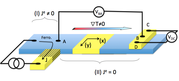
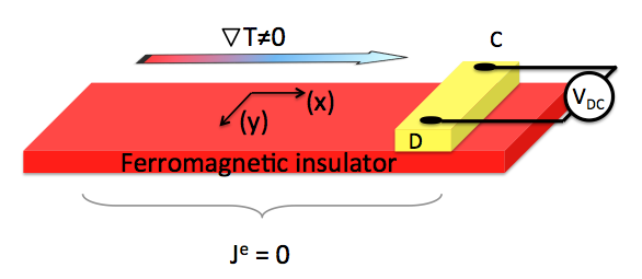
72.25.Mk, 85.75.-dThe role played by thermoelectric effects in the context of giant magnetoresistance (GMR) has long been recognized MTEP1 ; MTEP2 ; Shi ; Piraux ; Gravier ; Fukushima and exploited for possible applications in spintronics. Indeed, spin-dependent Seebeck and spin-dependent Peltier measurements are direct generalizations of giant magnetoresistance experiments performed in the presence of temperature gradient, that can be described in the framework of the two spin-channel model for conduction electrons Johnson ; Wyder ; Valet ; PRB2000 . Starting from the coupled transport equations of thermoelectricity, the introduction of the spin-dependent conduction coefficients and the spin-dependent Seebeck cross-coefficients suffices to describe most of the spin-dependent thermoelectric effects in electric conductors Sinova ; Tulapurkar ; Bauer ; Fabian ; Uchida_theo ; Nunner ; MTEP ; Gravier2 . However, recent experiments pioneered by the group of Uchida et al. Uchida ; Jaworsky ; Uchida2 ; Sharoni ; RezendePRL ; Rezende and still not well understood Sinova ; Bauer ; Fabian opened the way to a new class of spintronics effects in which no electric current is flowing and only spin-dependent heat currents are present in the sample. Such experiments are performed in electric conductors in the so-called non-local geometry (Fig. 1) at a long distance from the current injection, or in electrical insulators (Fig. 2).
The goal of this work is to propose a phenomenological description of spin-accumulation produced by spin-dependent heat currents. The model first describes the spin-thermocouple effect that allows spin-accumulation to be generated by a temperature gradient in conductors over arbitrarily large distances. This spin-dependent version of the thermocouple effect (that allows a temperature difference to be measured with a voltmeter in an open circuit), is corollary of the Seebeck effect (that allows an electric current to be generated with a temperature difference in a closed circuit). Both effects are deduced from the same thermoelectric transport equations with different boundary conditions and different power dissipation. The model is then applied to the case of electric insulators within the two spin-channel model of heat conduction. Finally, the transverse spin-dependent thermocouple effect occurring in the spin- Hall or spin-Nernst detector is also described. In all cases, the corresponding diffusion equations for the spin-accumulation are derived.
For a non-isothermal ferromagnetic material - that can be an electric conductor or an electric insulator - the system under interest is composed of a statistical ensemble of out-of-equilibrium heat carriers of two different species: the heat carriers that carry a up spin and the heat carriers that carry a down spin . In the case of electric conductors, the spin-dependent heat carriers are also electric carriers, while for electric insulators, the spin-dependent heat carriers are spin-dependent excitation modes (e.g. magnons). In both cases however, the two sub-systems of and heat carriers are described by the corresponding local chemical potential and , assuming the hypothesis of local equilibrium DeGroot . In line with the description of the giant magnetoresistance Johnson ; Wyder ; Valet , we define the thermal spin-accumulation by the difference of the two chemical potentials of the heat carriers. In the framework of the non-equilibrium thermodynamic theory, the bivaluated spin variable defines an internal degree of freedom DeGroot ; PRB2000 ; Entropy . The spin-relaxation occurring during the transport process is then treated as a chemical reaction that transforms heat carriers from the up channel to the down channel or inversely. The rate of this reaction is a flux of spin variable in the spin space. Since this reaction changes the density of the heat carriers of the spin channels, the corresponding chemical affinity is . The Onsager relation that links the flux to the force takes the same form as for electric spin-accumulation PRB2000 ; Entropy ; MTEP :
| (1) |
where we have introduced the phenomenological Onsager coefficient that describes the spin-dependent relaxation. At stationary regime (i.e. for the state of minimum entropy production of the system), the internal energy densities and obey the following conservation equations:
| (2) |
where describes the dissipation out of the system (e.g. by radiation) and describes the spin relaxation from one heat conduction channel to the other.
In the case of electric conductors and in a first approximation, the heat carriers and the electric carriers are the same, so that the chemical potentials of the heat conduction channels is also that of the electric conduction channels. The well-known thermoelectric transport equations relate the electric currents and the heat currents to the corresponding forces and MTEP ; Nunner ; McGraw :
| (3) |
| (4) |
where is the spin-dependent Fourier coefficient and is the spin-dependent Peltier coefficient. The electrochemical potential reads where is the charge of the electric carriers and the electric voltage. We assume that the temperature dependence of the transport coefficients is negligible.
The condition for the partial equilibrium is then given by
| (5) |
Eqs. (5) can be reformulated with introducing the total Seebeck coefficient :
| (6) |
and the Seebeck asymmetry coefficient :
| (7) |
Eq. (6) is nothing but the equation of the thermocouple. Equation (7) is, in contrast, a direct consequence of the presence of spin-dependent Seebeck coefficients, and describes the spin-dependent thermocouple effect. Accordingly, it is expected that a gradient of temperature produces a spin-accumulation gradient without electric current and without non-local spin injection. The usual thermocouple effect allows the spin-accumulation generated by the temperature gradient to be measured: inserting Eq. (7) in to Eq. (6) we obtain:
| (8) |
Eq. (8) is able to account for the observed Spin- Seebeck effects measured without electric current () at a distance arbitrarily large in the configuration of Fig. 1. The integration between the points and leads to the spin-dependent potential measured:
| (9) |
On the other hand, Eqs. (3) to Eq. (8) can be generalized with the introduction of tensorial transport coefficients , ( ) where the non-diagonal elements account respectively for the Hall effect SpinHall and the corresponding Nernst effect in homogeneous isotropic materials DeGroot . The detection of the transverse potential difference performed on the right electrode in Fig. 1 and Fig. 2 is described by the transverse spin-dependent thermocouple effect, or spin-dependent Nernst effect. If , the projection of Eq. (7) over the axis gives, after integration:
| (10) |
Eq. (9) and Eq. (10) are analogous to that of the usual spin-accumulation calculation for the giant magnetoresistance effect, with the difference that the spin-accumulation is produced by the heat current instead of the electric current, and that the spin-accumulation and are no longer governed by the usual diffusion equation of the spin-accumulation generated by electric current injection Johnson ; Wyder ; Valet ; PRB2000 .
Defining the total heat flux along the axis (see Fig. 1 and Fig. 2) and he spin-dependent heat flux , we have from Eq. (4):
| (11) |
where , , , , and .
Note that for , the flow is a “pure spin-current” Sinova ; Bauer that cannot be distinguished from its electric homologue with (and more generally, a “pure spin-current” is independent of the nature of the spin carriers involved).
Inserting Eq. (11) and Eq. (1) into Eq. (2), we deduce the diffusion equation for :
| (12) |
where we have introduced the thermal spin-diffusion length for conducting materials
| (13) |
and the constants , .
Assuming a uniform temperature gradient and negligible external dissipation , the solutions of Eq. (12) have the form where and are constants imposed by the boundary conditions. It is the same solutions as that of the usual spin-accumulation responsible for GMR effects, with the difference that the diffusion length is defined with the help of the Peltier asymmetry coefficient instead of the asymmetry of the electric conductivity, and plays the role of the usual spin-flip Onsager coefficient PRB2000 ; Tulapurkar .
In the case of spintronic devices with electric insulators (Fig. 2), there are no electric carriers and the chemical potentials are that of the corresponding heat carriers only (magnon, spin-dependent phonon, etc). The heat current is composed of a drift part and a diffusion part , where is the corresponding Onsager coefficient related to the diffusion coefficient , where is the density of the heat carriers (for the sake of simplicity, we assume isotropic diffusion). In the configuration of Fig. 2, the transport equations reads:
| (14) |
The diffusion equation for the chemical potential difference (i.e. spin accumulation) is deduced by inserting Eq. (14) and Eq. (1) into Eqs. (2):
| (15) |
where we have introduced the thermal diffusion length for electric insulators
| (16) |
where and . On the other hand, and .
This spin-accumulation in the electrical insulator is transferred to a conducting electrodes through the condition of continuity of the heat currents at the interface. In that case also, the final profile of the spin-accumulation throughout the insulator/conductor interface is similar to that of the usual GMR spin-accumulation under electric current.
In conclusion, the two spin-channel model has been applied to spin-dependent heat transport, in a circuit that is closed from the point of view of heat currents, and open for the point of view of electric currents. The result of the model shows that the heat current is able to play the same role as the electric current in a usual “local” spin-valve system, whatever the spin-dependent heat carriers considered. In particular, spin-injection and spin-accumulation can be performed with spin-dependent heat currents only at an interface. The model explains the recent observations of spin-dependent voltage measured in electric conductors of electric insulators, in the configurations depicted in Fig. 1 and Fig. 2.
References
- (1) M. J. Conover, M. B. Brodsky, J. E. Mattson, C. H. Sowers, S. D. Bader, J. Mag. Mag. Magn. 102, L5 (1991),
- (2) J. Sakurai, M. Horie, S. Araki, H. Yamamoto, and T, Shinijo, J. Phys. Sot. Jpu. 60, 2522 (1991).
- (3) J. Shi, R. C. Yu, S. S. P. Parkin, and M. B. Salamon, J. Appl. Phys. 73, 5524 (1993).
- (4) L. Piraux, M. Cassart, E. Grivei, M. Kinanyalaoui, J. S. Jiang, J. Q. Xiao, C. L. Chien, J. Mag. Mag. Magn. 136, 221 (1994).
- (5) L. Gravier, A. Fàbiàn, A. Rudolf, A. Cachin, J.-E. Wegrowe, J.-Ph. Ansermet, J. Mag. Magn. Mat. 271, 153 (2004).
- (6) A. Fukushima, H. Kubota, A. Yamamoto, Y. Suzuki, and S. Yuasa, IEEE Trans. Mag. 41, 2571 (2005).
- (7) M. Johnson, R. H. Silsbee, Phys. Rev. Lett. 55, 1790 (1985)
- (8) P. C. van Son, H. van Kempen, P. Wyder, Phys. Rev. Lett. 58, 2271 (1998)
- (9) T. Valet, A. Fert, Phys. Rev. B 48, 7099 (1993) .
- (10) J.-E. Wegrowe, Phys. Rev. B 62, 1067 (2000).
- (11) A. A. Tulapurkar and Y. Suzuki, Phys. Rev. B 83 (2011).
- (12) J. Sinova, Nature Mater. 9, 880 (2010).
- (13) G. E. W. Bauer, E. Saitoh, and B. J. van Wees, Nature Mat. 11, 391 (2012).
- (14) B. Scharf, A. Matos-Abiague, I. Zutić, and J. Fabian, Phys. Rev. B 85, 085208 (2012).
- (15) K. Uchida, H. Adachi, T. Ota, H. Nakayama, S. Maekawa, J. Ieda, K. Harii, K. Ikeda, W. Koshibae, K. Ando, S. Maekawa, and E. Saitoh, J. Appl. Phys. 105, 07C908 (2009).
- (16) T. S. Nunner anf F. von Oppen, Phys. Rev. B 84, 020405(R), 2011.
- (17) J.-E. Wegrowe, Q. Anh Nguyen, M. Al-Barki, J.-F. Dayen, T. L. Wade, and H.-J. Drouhin, Phys. Rev. B, 73, 134422 (2006).
- (18) L. Gravier, S. Serrano-Guisan, F. Reuse, and J.-Ph. Ansermet, Phys. Rev B 73, 024419 (2006).
- (19) K. Uchida, S. Takahashi, K. Harii, J. Ieda, W. Koshibae, K. Ando, S. Maekawa, and E. Saitoh, Nature 455, 778–781 (2008),
- (20) C. M. Jaworsky, J. Yang, S. Mack, D. D. Awschalom, J. P. Heremans, and R. C. Myers, Nature Mater. 9, 898 (2010).
- (21) K. Uchida, H. Adachi, T. Ota, H. Nakayama, S. Maekawa, Appl. Phys. Lett. 97, 172505 (2010).
- (22) M. Erekhinsky, F. Casanova, I. K. Schuller, and A. Sharoni, Appl. Phys. Lett. 100, 212401 (2012).
- (23) E. Padrón-Hernández, A. Azevedo, and S. M. Rezende, Phys. Rev. Lett. 104 197203 (2011).
- (24) G. L. da Silva, L. H. Viela-Leao, S. M. Rezende, and A. Azevedo, J. Appl. Phys. 111, 07C513 (2012).
- (25) S. R. De Groot, P. Mazur, Non-equilibrium Thermodynamics; North-Holland: Amsterdam, The Netherlands, 1962.
- (26) J.-E. Wegrowe and H.-J. Drouhin, Entropy 13, 316 (2012).
- (27) Without the spin indices, the microscopic derivation of the coupled Eqs. (3) and (4) (with explicit expressions of the phenomenological transport coefficients , , and ) can be found e.g. in A. C. Smith, J. Janak, and R. B. Adler, Electronic Conduction in Solids, Physical and Quantum Electronics Series McGraw-Hill, New York, 1967, page 4, Eqs. (1.3a) and (1.3b), and page 169, Eqs. (7.56) and following.
- (28) T. Jungwirth, J. Wunderlich and K. Olejn k, Nature Mat. 11, 382 (2012).