Magnetic orders and spin-flop transitions in the cobalt doped multiferroic
Abstract
We present a comprehensive single-crystal neutron diffraction investigation of the with . At lower concentration , the system is quickly driven into the multiferroic phase with spin structure forming an elliptical spiral order similar to the parent compound. The reduction of electric polarization is ascribed to the tilting of the spiral plane. For , the magnetic structure undergoes a spin-flop transition that is characterized by a sudden rotation of the spin helix envelope into the plane. This spin structure persists for concentration up to , where additional competing magnetic orders appear at low temperature. For , the system experiences another spin-flop transition and recovers the low- spiral spin configuration. A simple commensurate spin structure with is found to coexist with the incommensurate spiral order. The complex evolution of magnetic structure in Co doped contrasts sharply with other transition metal ion doped (A=Zn, Mg, Fe) where the chemical substitutions stabilize only one type of magnetic structure. The rich phase diagram of results from the interplay between magnetic frustration and spin anisotropy of the Co ions.
pacs:
75.30.Kz,75.25.-j,61.05.F-,75.58.+tI Introduction
The observation of spontaneous electric polarization and magnetic control of ferroelectricity in perovskite manganite TbMnO3Kimura et al. (2003) has inspired much theoretical and experimental efforts searching for new magnetoelectric multiferroic materials due to their great technological and fundamental importance.Khomskii (2006); Tokura (2007); Cheong and Mostovoy (2007) New magnetic multiferroics among transition metal oxides have since been discovered that include rare-earth manganite derivative MnO3 and Mn2O5 (: Y, Gd, Dy),Goto et al. (2004); Kimura et al. (2005); Higashiyama et al. (2004); Hur et al. (2004) geometrically-frustrated triangular lattice CuO2 (: Fe,Cr),Kimura et al. (2006, 2009) kagome lattice antiferromagnet .Lawes et al. (2005) In the conventional (type-I) ferroelectric materials, the electric polar state arises either from the covalent bonding between filled-shell oxygen atoms and the empty -shell nonmagnetic transition metal ion (e.g., BaTiO3),Cohen (1992) or the inversion symmetry breaking caused by the 6 orbital (lone pair) that moves away from the centrosymmetric position (e.g., BiMnO3).Seshadri and Hill (2001) Even if magnetic ions are present in these materials, the spins order at much lower temperature than the electric dipoles and the effect of magnetic transition on the dielectric constant is weak. In contrast, the new family of magnetoelectric multiferroics (type-II) exhibits an exceptionally strong sensitivity to an applied magnetic field that causes reversal and sudden flops of the electric polarization.Kimura et al. (2003, 2005); Hur et al. (2004) Such a level of control indicates the electric polarization is induced by the magnetic order, which typically has an incommensurate noncollinear spiral configuration. The onset of ferroelectricity correlates with the transition to the spiral spin order. The intimate link between these two order parameters marks the prominent and intriguing feature of the new class of multiferroics.
The mineral hübnerite MnWO4 (monoclinic, P2/c) is one of the few multiferroics that is ideal for studying the complex spin orders caused by magnetic frustrations and the interplay between magnetism and ferroelectricity.Taniguchi et al. (2006); Arkenbout et al. (2006); Heyer et al. (2006) Without chemical doping, the parent compound undergoes sequential magnetic transitions in zero magnetic field.Lautenschläger et al. (1993); Ehrenberg et al. (1997) The system first enters a collinear spin structure (AF3) around 13.5 K with sinusoidal modulation of the magnetic moment, the corresponding incommensurate (ICM) wave vector appears at and the moment of the Mn ions are confined in the plane at an angle of 35∘ towards the axis. At 12.6 K, an ICM elliptical spiral spin order (AF2) sets in, accompanied by the spontaneous electric polarization along the crystallographic axis. The magnetic order at AF2 phase has the same magnetic wave vector while the helix spin structure is characterized by the moment tilting out of the plane towards the axis. As the system is further cooled below 7 K, the ICM magnetic order is replaced by a commensurate (CM) magnetic order (AF1) that also suppresses the electric polarization. The close proximity of three different magnetic phases and the metamagnetic transitions prove the existence of significant magnetic frustration in the system, as revealed by inelastic neutron scattering measurements.Ehrenberg et al. (1999); Ye et al. (2011) Consistent with theoretical studies,Tian et al. (2009); Matityahu et al. (2012), the investigation of spin wave excitations in the low- spin order indicates that the collinear spin state results from the balance of long range magnetic interactions between Mn2+ ions up to 11th neighbors.Ye et al. (2011) Higher-order magnetic exchange interactions have strengths comparable to the nearest neighbor exchange coupling along the zigzag spin chain in the axis and between the zigzag chains in the axis direction. However, the magnetic interactions between the chains in the axis are much weaker. This finding suggests that different magnetic structures are close in energy and compete for the magnetic ground state. Like other multiferroic materials, the magnetic and ferroelectric phases in this system are expected to be tunable with small perturbations of magnetic field,Taniguchi et al. (2006); Higashiyama et al. (2004); Hur et al. (2004); Seki et al. (2008) pressure,dela Cruz et al. (2007); Chaudhury et al. (2008); dela Cruz et al. (2008); Chaudhury et al. (2007) and even chemical substitution with various transition metal ions. MnWO4 is known to form stable compounds when Mn is replaced by Fe,Kleykamp (1980); García-matres et al. (2003) Co, Ni, Cu,Weitzel (1970) or Zn.Takagi et al. (1981) It was reported that the chemical doping with magnetic Fe ions stabilize the low- collinear and CM spin order.Ye et al. (2008); Chaudhury et al. (2009); Liang et al. (2011) Both neutron diffraction and electric polarization measurements show that the low- magnetic ground state is completely converted into the collinear spin order (AF1 phase) with 5% of Fe substitution, which is largely due to the increased Fe single ion anisotropy.Ye et al. (2012) In contrast, substitution with nonmagnetic ions (Zn or Mg) has been shown to alter the magnetic ground state differently; replacement of only a few percent of nonmagnetic ions seems to be sufficient to suppress the commensurate AF1 phase and stabilize the spiral spin order.Meddar et al. (2009); Chaudhury et al. (2011) A similar effect was also observed in the Co-substituted compound by neutron diffraction and bulk magnetic measurements on polycrystalline samples. Song et al.Song et al. (2009) found that the CM collinear state is replaced by the ICM spiral phase with 5% Co concentration; a spin-flop transition occurs with increasing Co doping with the corresponding spiral plane tilting away from the axis. The modification of the magnetic structure is expected to switch the electric polarization direction from the to the axis as it was later confirmed in a single crystal of .Song et al. (2010); Urcelay-Olabarria et al. (2012a) However, it was discovered that with further increasing of Co doping ( 15%), the only measurable polarization was along the axis.Chaudhury et al. (2010) This result indicates that a new type of spin structure responsible for the axis polarization is bound to a narrow range of Co substitution and the actual phase diagram of the is more complex than the one reported from powder diffraction studies.Song et al. (2009)
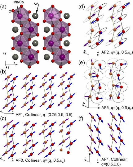
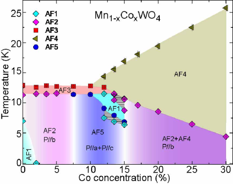
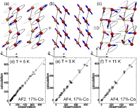
To elucidate the nature of the magnetic ground state upon Co doping, we performed a comprehensive neutron single-crystal diffraction study of the doped . We observed a systematic evolution of the magnetic structure with increasing Co doping. The spin configurations for different phases are depicted in Fig. 1. For lower concentration (), the system exhibits a spiral spin configuration similar to the undoped MnWO4, but with decreased angle between the normal axis of the spiral plane and the axis. At , the system undergoes a magnetic transition to a phase in which the spin helix flops into the plane. The spiral spin structure and the associated polarization and survive in the range of . For higher Co concentration, the system experiences a second spin-flop transition such that the spin order switches back to low- spiral structure coexisting with a collinear CM magnetic structure as observed in pure CoWO4.Forsyth and Wilkinson (1994) The complete phase diagram shown in Fig. 2 of Co-substituted MnWO4 is obtained based on the neutron diffraction and bulk property measurements. The chemical substitution of the magnetic Co ion provides an unique method to fine tune the magnetic property that is capable of achieving magnetoelectric control with multiple value states.
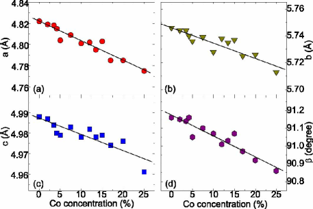
Single crystals of with thirteen different compositions () have been grown in a floating zone optical furnace. We use powder x-ray diffraction to check the phase purity of the polycrystalline feed rod before the crystal growth. No impurity phase could be detected within the resolution of the spectra. The chemical composition and the Co content of the single crystals were verified by energy-dispersive x-ray (EDX) measurements testing up to 15 different spots of a single crystal. As further confirmed by neutron diffraction measurement, the refined Co content of all samples was close to the nominal composition. In the following sections, we will use the nominal composition to distinguish between different substitution levels. Single crystal neutron diffraction experiments were carried out at the High Flux Isotope Reactor of the Oak Ridge National Laboratory. We used the HB1A, HB1, and HB3 triple axis spectrometers to study the doping and temperature evolution of the magnetic diffraction pattern. We chose an incident neutron beam with wavelength of 2.366 and pyrolytic graphite (PG) crystals as monochromator and analyzer. The crystals were aligned in several scattering planes to probe different magnetic reflections. For nuclear and spin structure determination, we used the HB3A four-circle diffractometer to collect both the nuclear and magnetic reflections with neutrons of wavelength 1.536 at selected temperatures. The crystal and magnetic structure refinement were performed using the fullprof suite package.Rodríguez-Carvajal (1993) Magnetic representation analysis is performed to choose appropriate basis vectors to describe the various spin structures. The sample temperature was regulated either using a closed cycle refrigerator (CCR) or liquid Helium cryostat. All samples under study belong to the monoclinic P2/c (No. 13) space group. With increasing Co concentration , the lattice parameters of and the angle of systematically decrease over the range studied, as determined by the x-ray powder diffraction measurement shown in Fig. 3.
II magnetic order at low concentration ()
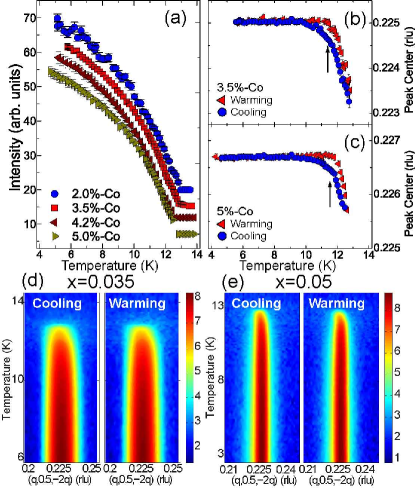
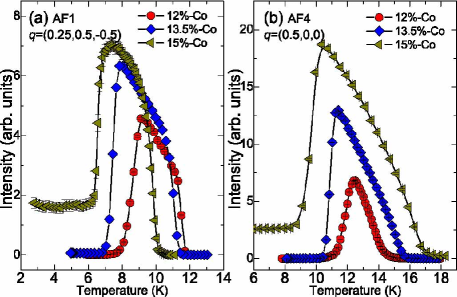
We start with the neutron diffraction results of the lower Co concentration. The samples were aligned in a horizontal scattering plane defined by two orthogonal vectors of [1,0,-2] and [0,1,0]. Although the magnetic propagation wave vectors in the pure MnWO4 is determined to be that deviates slightly from the scattering plane used in the measurement, the coarse vertical resolution of the triple axis spectrometer is sufficient to capture the magnetic Bragg reflections and track their temperature and doping evolution. In the rest of the paper, we will use the wave vector , which is the projected value in the horizontal scattering plane, to denote the ICM magnetic Bragg peak unless specified otherwise. Figure 4 summarizes the thermal evolution of the ICM magnetic order at lower cobalt concentration with , and 0.05. The integrated intensities of magnetic scattering for these samples grow monotonically below 13 K without any sign of anomaly at lower temperatures. Such behavior contrasts with the undoped MnWO4 where the multiferroic AF2 phase is sandwiched between the high- AF3 and the low- AF1 phases, resulting in an abrupt suppression of the ICM magnetic scattering. Like the nonmagnetic Zn and Mg doping,Meddar et al. (2009); Chaudhury et al. (2011) the multiferroic state associated with the noncollinear ICM phase is stabilized with Co substitution and becomes the ground state. The dependence of the integrated intensities does not separate the phase boundary between the high- AF3 and the multiferroic AF2 phases [see Fig. 4(a)]. However, there are clear changes of the peak center across the phase transition that label the phase boundary between the collinear and noncollinear phases. In addition, the peak position is independent of the temperature in the AF2 phase, but changes continuously in the AF3 phase, as demonstrated in Figs. 4(b) and 4(c) for the and 0.05 samples.
| nominal | ||||||
|---|---|---|---|---|---|---|
| 0.02 | 3.86(5) | 4.44(6) | 0.49(4) | 28.4(9) | 4.22 | |
| 0.035 | 3.91(5) | 4.42(6) | 0.47(4) | 19(2) | 5.83 | |
| 0.042 | 3.86(6) | 4.52(9) | 0.52(5) | 20(1) | 5.71 | |
| 0.05 | 3.82(5) | 4.33(6) | 0.47(4) | 15(1) | 4.90 | |
| 0.075 | 3.47(5) | 4.62(6) | 0.66(3) | 6(1) | 7.56 |
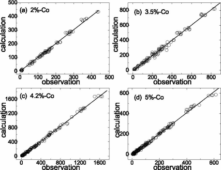
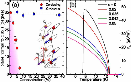
The magnetic configurations of the AF2 phase for at low can be determined using single crystal magnetic diffraction experiments. As summarized in Table 1, the refinement parameters indicate the spin structure is well described by the elliptical spiral as in the pure MnWO4 and the doped .Lautenschläger et al. (1993); Chaudhury et al. (2011) Figure 5 shows the agreement between model calculation and experimental observations for all samples. Contrary to the Zn substitution, where the angle between the normal vector of the spiral plane and the crystallographic axis remains constant for Zn concentration up to , the value of shows a gradual decrease with increasing Co concentration [see Fig. 6(a)]. The refinements also indicate a considerable deviation of the ellipse from a perfect circular envelope as quantified in the Table 1. To correlate the spin structure and the ferroelectric properties, Fig. 6(b) displays the dependence of electric polarization at different . Clearly, a smooth decrease of the saturated polarization along the axis is observed, a trend similar to the doping dependence of the angle . Within the microscopic picture of spin current or inverse Dzyaloshinskii-Moriya (DM) model,Katsura et al. (2005); Mostovoy (2006); Sergienko and Dagotto (2006) the expected electric polarization can be expressed as
| (1) |
where is the unit vector connecting the neighboring spins and , and is a constant related to the spin-orbit coupling and spin exchange interaction.Katsura et al. (2005); Mostovoy (2006); Sergienko and Dagotto (2006) The inset of Fig. 6 describes a general spin helix configuration; the normal vector of the spiral plane has angle with respect to the axis and its projection in the plane has angle towards the axis. Using spherical coordinates, we can express , where are the unit vectors along the Cartesian coordinates (). Since the angle between the crystallographic and axes is close to 90∘, we will consider , , and for the sake of simplicity. The magnetic moments of two spins in the chemical unit cell for the helical state can be expressed as
| (2) |
where is the position vector of the Mn site in the unit cell , is the magnetic propagation wave vector of the spiral structure, , and and are the long and short half axes of the magnetic ellipse, respectively. If we consider the dominant magnetic exchange coupling is along the axis zigzag chain, the electric polarization can be quantitatively written as
| (3) |
If, however, there is additional non-negligible exchange interactions between the chains along the axis, the extra contribution to the polarization is
| (4) |
where , are constants independent of , and only related to the spin-orbit coupling and magnetic interaction, , are components of the ICM magnetic wave vector. The spin structure refinement in the AF2 phase reveals ; this leads to a simplified form of and , both contributing to the axis polarization. If there are no significant deviations of the ellipticity and the moment size (Table I), the magnitude of depends solely on the angle . With both and taken into account, the total electric polarization becomes . It is evident that the polarization will change from to upon variation of from 90∘ to 0∘. In addition, we note that due to a shorter exchange path along the zigzag chain direction ( along the axis versus along the direction), the expression can be further simplified as . One can then estimate that the saturated polarization decreases to due to the rotation of the spiral plane, which is close to the measured value. The close correlation between the rotation of the spin helix plane and the decreasing ferroelectric polarization emphasizes that the doped MnWO4 is indeed a prototypical multiferroic material with inverse DM mechanism being the origin of the spontaneous electric polarization.
III magnetic order at intermediate concentration ()
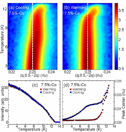
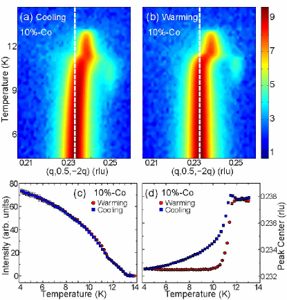
As the Co concentration increases to , ferroelectric polarization measurement does not detect any significant axis component within the resolution of the experiment.Liang et al. (2012) However, a large polarization was found along the axis accompanied by a small component along , which implies that the system undergoes major change in spin structure that causes the reorientation of the polarization. To correlate the polarization result, we studied the dependence of the wave vector scans upon cooling and warming as displayed in Figs. 7(a)-(b). One can clearly observe a strong hysteresis in the magnetic scattering during thermal cycling. Upon cooling, the peak center shifts from that is associated with the high- collinear AF3 phase and moves into a plateau with another ICM wave vector for 7 K11 K [Figs. 7(a) and 7(d)]. As the sample is further cooled to lower temperature, the magnetic peak resumes shifting and finally locks into the low- ICM phase with . On warming, the same low- magnetic order remains at the wave vector till 10 K and suddenly is converted to the high- collinear AF3 phase.
To understand the complex evolution of the magnetic order, the same sample was placed on the four-circle diffractometer to investigate the spin structure. We chose the cooling protocol and collected data at two characteristic temperatures K and 4.5 K. Figures. 8(a) and 8(b) display the refined spin configurations. At K, the magnetic spins form an spiral structure (termed as AF5 phase) with two principle axes of the ellipse lying along the crystallographic and directions. The normal vector of the new spiral plane is characterized by and . According to Eqn. (1), such a magnetic structure will cause the rotation of into other directions. If we only consider that the dominant magnetic interactions are along the spin chain direction ( axis), the cross product of and would only induce the axis electric polarization in a form of
| (5) |
where and are the projected moments of the spin helix along and . This prediction only agrees partially with the experimental observation where both and develop below 10 K.Liang et al. (2012) To explain the presence of , we have to consider the interchain magnetic interactions along the axis. Recent spin wave measurements in MnWO4 have revealed that the interchain magnetic interactions are of the same order as the intrachain exchange coupling in its collinear spin state.Ye et al. (2011) Although the results obtained are for the collinear spin structure, it is expected they will have similar strength when the system enters the noncollinear AF2 phase, based on what has been found in the pure CuFeO2 and the multiferroic .Ye et al. (2007); Haraldsen et al. (2010) Taking the interchain magnetic interactions into account, the contribution to the electric polarization has the form of
| (6) |
This prediction of small polarization along is in accordance with the bulk polarization measurement. We note that although the spins of the AF5 phase remain in the plane, the expressions of Eqns. 5 and 6 indicate a -dependent eccentricity that can further modify the magnitude of the electric polarization.
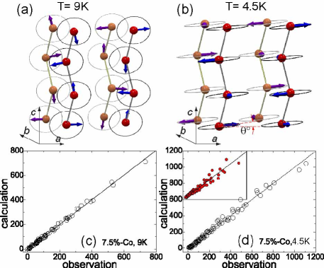
With the sample cooled below 8 K, it was found that both and are suppressed. Such behavior suggests a gradual change of the spin structure that might be due to either the distortion of the elliptical envelope or the rotation of the spiral plane. Since both polarizations are proportional to for an spiral structure, the increased eccentricity of the spiral ellipse could certainly yield a reduced bulk polarization. On the other hand, the rotation of the spiral plane away from the plane can also lead to the suppression of polarization along both directions. The spin structure determination with data collected at 4.5 K provides a definitive answer to separate those two possibilities. As shown in Fig. 8(b), the system at base temperature shows a completely different spin structure from the one at 9 K. It possesses the configuration similar to the low Co concentration with the short axis of the spin ellipse along the axis and the long axis residing in the plane. The canted angle between the spiral plane normal vector and the axis is . The result reveals that the sample is located near the boundary between distinct spin configurations of the low- spiral and the spiral structure.
To understand the spin flop transition near , we recall that the spiral spin order allows the coupling linear in gradient of the magnetic order parameter (also known as Lifshitz invariant) with broken inversion symmetry and induces a uniform electric polarization according to the Ginzburg-Landau approach.Mostovoy (2006) The energy gain originating from the nonlinear coupling between and () and the corresponding electric polarization is proportional to the angle . With increasing Co concentration, both the electric polarization and the energy gain decrease because of the decreasing angle. It is not surprising that exists a critical concentration , around which the system can no longer gain energy to maintain the magnetic structure. Such instability will then bring about a spin flop transition to the observed spiral which can reduce the free energy further because of the sizable polarization. Compared to other multiferroics, the continuous change in the magnetic wave vector from the transition between different spin configurations of the Co doped MnWO4 appears rather rare. The gradual transition highlights that the high- spiral and the low- spiral spin structures are nearly degenerate in energy such that a small change in temperature would drive the system between competing magnetic states characterized by a continuous rotation of the spiral plane.
Figures. 9(a)-9(d) show the neutron diffraction results on the sample. The hysteresis of the magnetic order upon thermal cycling is still discernible. However, the shift of the magnetic wave vector is much smoother upon cooling and does not show the plateau as seen at . Accordingly, electric polarizations show continuous growth upon cooling. The saturated and reach 100 and 30 at 4 K, respectively. exceed the maximum -axis polarization of MnWO4 by nearly a factor of two. This result is consistent with the predicted in Eqn. (5) assuming unchanged coefficient in the AF2 and AF5 phases. On warming, the low- spin structure remains till 11 K and a transition to the high- collinear AF3 phase occurs. The lack of an abrupt change in the ICM wave vector suggests the modification of the spin structure is not as drastic as the sample and the same ICM spin structure is preserved to the lowest temperature. In a recent neutron diffraction study on the sample, Urcelay-Olabarria et al. obtained a similar result and found that the magnetic spins remain in the plane at all temperatures while the eccentricity reduces from at 9 K to 0.42 at 2 K, suggesting the spiral ellipse becomes more circular at lower temperature.Urcelay-Olabarria et al. (2012a) This decrease of the eccentricity upon cooling further increases the electric polarization, as expressed in Eqns. (5) and (6). Another noteworthy feature in the sample is that the energy of the spiral structure is close to other competing state including the collinear AF1 phase. This can be appreciated by the weak magnetic reflection at the CM wave vector near 11 K [see Figs. 9(a) and 9(b)].
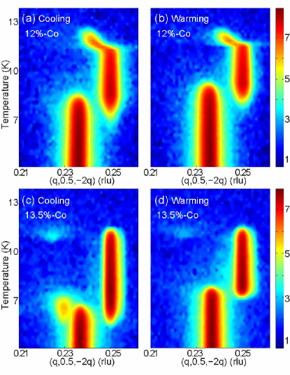
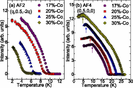
The evolution to other competing magnetic orders is manifested at higher Co concentration. Figure 10 displays the dependence of the wave-vector scans for two samples with and . At , the first magnetic order present in the scattering plane consisting of the and the directions is the collinear AF3 phase, which locks into the commensurate AF1 phase at lower temperature. With the sample cooled below 9.0 K, the previously observed AF5 phase sets in and extends to the lowest temperature without any noticeable shift of the magnetic wave vector. There is a narrow temperature window in which both the AF1 and AF5 phases are present between 6.8 K 9.0 K. On warming, the reverse order of the magnetic phases is observed except the coexisting region shifts up to 7.5 K 9.3 K. Interestingly, the order of appearance for the commensurate AF1 and the multiferroic AF5 phases is exactly opposite to the pure MnWO4, where the AF1 phase occurs at lower temperature. At , the transition between the collinear AF3 and the AF1 phases vanishes. There is very weak scattering near the ICM wave vector that exists in a very narrow range of 10.7 K11.3 K, which was later identified as the AF2 phase. The strongest intensity is only one percent of that for the AF1 phase and is too weak to induce any detectable polarization signal. We also observed the coexistence of the multiferroic AF5 phase and collinear AF1 phase. The coexisting region downshifts to 5.5 K K for cooling and 7.0 K7.8 K for warming. At lower temperature, the AF1 phase is completely suppressed.
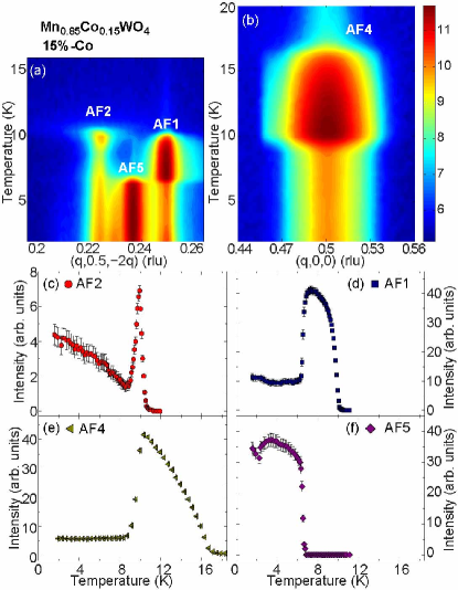
The sample is probably the most complex system with a minimum of five coexisting magnetic phases.Chaudhury et al. (2010) Figure 11 summarizes the thermal evolution of the various magnetic orders probed at two scattering planes. Figure 11(a) shows the dependence of wave-vector scans along the direction where the AF1, AF2, and AF5 can be surveyed. Figure 11(b) displays the scans along the direction where the commensurate AF4 magnetic order with can be examined. Upon cooling, the AF4 phase first appears around 17 K and the intensity increases continuously till 10 K. A sharp drop in its intensity is accompanied by the simultaneous development of the commensurate AF1 and multiferroic AF2 phases. With the sample cooled below 6.6 K, the CM AF1 phase is also suppressed and an additional ICM AF5 phase develops at lower temperature. Figures. 11(c)-11(f) summarize the dependence of integrated intensities for the four major magnetic (the commensurate AF1, AF4 and incommensurate AF2, AF5) phases in the sample. Since the magnetic intensity of the AF2 phase closely follows the axis polarization , it is speculated that this state has a spiral spin structure similar to the samples. Notice even at the lowest temperature, there are finite magnetic scattering from the commensurate AF1 and AF4 phases.
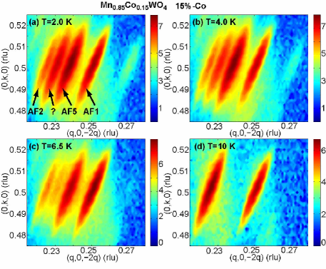
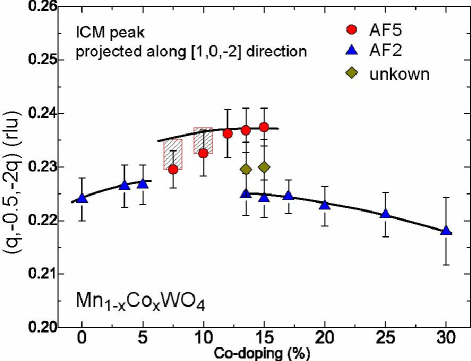
To confirm the coexistence of various magnetic orders, we have performed an extensive survey in the reciprocal space at selected temperatures, 2.0, 4.0, 6.5, and 10 K, as shown in Fig. 12. The appearance and disappearance of competing magnetic orders is evident. At 10 K, only the AF2 with and AF1 with phases are present, while more magnetic Bragg peaks appear at lower temperature. A distinct magnetic reflection appearing as the shoulder of the AF5 Bragg peak becomes visible in the low- mapping [see Figs. 12(a) and 12(b)]. The peak is located between the AF2 and AF5 phases with wave vector . The exact nature of this magnetic order remains unknown since its reflection is too close to the neighboring AF2 and AF5 Bragg peaks. This unknown magnetic phase is already present at , but only exists within a narrow temperature range [see Fig. 10(c)]. This magnetic fluctuation continues to grow in intensity upon cooling at . Together with the already identified commensurate AF1,AF4 phases and incommensurate AF2,AF5 phases, there are five magnetic orders at the lowest temperature. Such remarkable coexistence of many competing magnetic phases marks the sample as the most frustrated system.
Table II lists the refined magnetic structures for the , and 0.135 samples in the AF5 phase as well as the commensurate AF1 and AF4 phases for the sample. As mentioned in Sec. III, the sample is located near the phase boundary between the low- spiral and the spiral structures; its magnetic structure can be refined as an spiral configuration only for K. In contrast, the magnetic ground states of the samples are well described by the same spiral structure at low temperatures. Although the ICM magnetic order seems to be the only low- phase for the sample, it cannot be refined by a pure spiral structure implying the deviation from that configuration. To get good agreement between the observation and model calculation, a combined low- spiral and spiral structure is chosen to fit the experimental data and yields satisfactory result. The spin structure is best characterized as a modified helical structure that the normal vector of the spiral plane tilts way from the axis. Such spin order results in a reduction of electric polarization and is consistent with the bulk measurement that both and decrease for .Liang et al. (2012)
| phase | moment () | |||||
|---|---|---|---|---|---|---|
| 0.135 | AF4 | 0.817(8) | -1.051(9) | 11.33 | ||
| 0.135 | AF1 | 3.13(3) | -2.07(4) | 8.08 | ||
| Real | Imaginary | |||||
| 0.075 | AF5 | 3.45(4) | 2.67(4) | 0.63(3) | 4.81 | |
| 0.10 | AF5 | 4.05(4) | 3.14(5) | 0.63(3) | 7.41 | |
| 0.12 | AF5 | 4.04(6) | 3.56(7) | 0.46(6) | 5.83 | |
| 0.135 | AF5 | 4.03(4) | 3.53(5) | 7.06 | ||
| -0.81(7) | -0.10(7) | |||||
With Co concentration , we have observed the expansion of both commensurate AF1 and AF4 phases as shown in Fig. 13. Overall, samples in this doping region form the commensurate AF4 spin structure with at higher temperature and enter directly the collinear AF1 phase upon cooling, which is different from pure MnWO4. With increasing , the transition to the AF1 state moves to lower temperature while the transition to the AF4 phase shifts to higher one. Although both phases at are completely suppressed at low-, they survive for the sample indicating the collinear spin structures gradually become the stable magnetic ground state at large . Magnetic structure refinements in this doping range reveal that the spin moments in the AF4 phase are confined in the plane, with an angle of towards the axis (see Table II). This spin reorientation is again due to the strong anisotropy of Co2+ ionsForsyth and Wilkinson (1994); Hollmann et al. (2010) that locks the Mn2+ spins in the same direction and makes the collinear spin structure more favorable with increasing . The spins in the collinear AF1 phase have a angle of with respect to the axis, which is different from pure MnWO4, and is probably due to the pinning of the high- AF4 magnetic structure.
IV magnetic order at high concentration ()
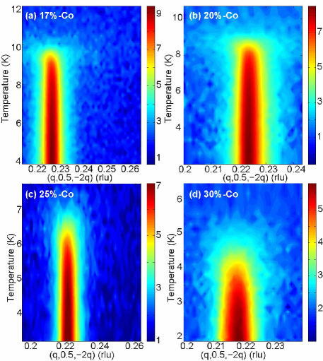
Finally, we focus on the magnetic structures for . The bulk polarization measurements show no detectable and . Instead, the polarization is pointing to the axis, the same direction as observed at lower Co concentration. Thus, the switch of the polarization suggests another major modification of the spin structure. Figure 14 compares the dependence of the wave-vector scans across the ICM peak of four Co doped samples with , and . The scattering profile in this doping regime exhibits different character. Unlike the coexistence of various competing magnetic orders in the intermediate doping regime, there is only one ICM magnetic reflection at the wave vector of . The transition temperature decreases from K at to K at . The scattering intensity of the ICM magnetic order is also suppressed with increasing as displayed in Fig. 15(a). Further survey in reciprocal space reveals one strong collinear AF4 phase that is established at higher temperatures and persists to the lowest temperatures [see Fig. 15(b)]. The transition temperature increases with Co concentration and reaches 25 K for the sample. For all samples studied, the magnetic intensities of the AF4 phase exhibit a kink at temperatures corresponding to the onset of the mentioned ICM magnetic order indicating the competition between the CM and ICM phases.
| phase | moment () | |||||
|---|---|---|---|---|---|---|
| AF4 | 11 K | 1.47(3) | -1.86(2) | 6.47 | ||
| AF4 | 5 K | 1.47(1) | -1.90(1) | 6.25 | ||
| Real | Imaginary | |||||
| AF2 | 5 K | 2.92(7) | 2.36(4) | 0.39 | 5.11 | |
Since all samples in this doping region show similar magnetic properties except the transition temperature, we chose the sample for the crystal and magnetic structure refinement and expect the other doped samples have smooth evolution of the spin structure. As demonstrated in Figs. 14 and 15, there are two major magnetic phases with ICM and CM wave vectors for . We collected 193 nuclear reflections at 5 K for the structural determination. One set of magnetic reflections for the low- ICM magnetic structure were collected to refine the spin structure and two sets of magnetic reflections with were collected at 5 and 11 K separately to investigate how the collinear AF4 phase is affected by the low- ICM magnetic order. Figures. 16(a) and 16(b) show the corresponding magnetic structures of the ICM spiral order and the CM AF4 phase. At 11 K, only the collinear AF4 phase exists, the magnetic spins form in a configuration identical to CoWO4, where the moments lie in the -plane, with an angle of towards the axis. With the sample cooled below 10 K where the ICM order sets in, the magnetic structure of the collinear spin order is not modified; the spins remain in the same direction and the total moment of 2.42(4) /site at 5 K is almost the same as 2.39(3) /site at 11 K (see Table III). On the other hand, attempting to refine the low- ICM order using the spiral structure gives a poor fit to the collected data. Consequently, we adopted the spin configuration at low Co concentration because such spin structure provides an electric polarization along the axis. As shown in Fig. 16(d), this model provides a good description of the experimental data. The spin moment of the spiral state varies from 2.36 to 2.92 , which is comparable with the moment size at the AF4 phase. The observation of spiral order with the helix plane similar to the low- case implies that the sample is located at another phase boundary where the system undergoes a second spin flop transition consistent with . However, there is one apparent difference between the and samples. There is only one ICM AF2 phase in the low Co concentration samples, while the ICM AF2 phase appearing in the high- samples coexists with the commensurate AF4 phase that is established at higher temperature. The simultaneous presence of two magnetic phases is similar to the colossal magnetoresistance related manganite (PCMO), in which both the ferromagnetic and antiferromagnetic components are observed at low temperature.Yoshizawa et al. (1995) This can be interpreted either as a canted antiferromagnetic structure or coexisting FM and AFM phases. Similarly, neutron diffraction data alone can not differentiate whether the observed coexistence of AF2 and AF4 orders in arises from two separated phases, each with distinct magnetic wave vector; or if they originate from one single phase with two- magnetic structure. Definitive identification would require a spatially sensitive probe in conjunction with the electric polarization measurement. Our neutron diffraction result at is consistent with a recent study on the sample, where the coexisting collinear AF4 and multiferroic AF2 phases are revealed.Urcelay-Olabarria et al. (2012b) Those authors concluded that the superposition of the competing AF4 and AF2 magnetic structures leads to a conical antiferromagnetic order that is depicted in Fig. 16(c).
V discussion and conclusions
The comprehensive single-crystal neutron diffraction measurement, in combination with the magnetic property and polarization measurements, make it possible to construct the phase diagram of the as a function of Co concentration and temperature. Unlike other transition metal ion doped MnWO4, where only one type of spin configuration is stabilized, a rich variety of spin structures and complex evolution between different phases are observed as the Co concentration is increased. The spin anisotropy of the Co ions plays a vital role in defining the low- magnetic structures. Although confined in the same plane, the spin easy axis in CoWO4 is from the axis, and is nearly 90∘ away from the easy axis direction in MnWO4.Weitzel (1970); Forsyth and Wilkinson (1994) With increasing , the long axis of the spiral ellipse that initially has a positive angle towards the axis will tilt gradually to the negative direction due to the single ion anisotropy of the Co2+. The rotation of the spin helix plane leads to a decrease of the electric polarization that is compatible with the magnetic symmetry, as well as the energy gain that is coupled to the . At the critical concentration of , the system cannot gain enough energy to maintain the multiferroic phase, thus results in the spin flop transition. The new spiral structure helps the system lower the free energy because of the large value of the ferroelectric polarization. For , the presence of the and instead of is consistent with an spiral spin structure, and highlights the significant intrachain as well as the interchain interactions. Although the samples in the intermediate doping exhibit similar spiral structure, the maxima of the electric polarizations only occur near . It results mainly from the rotation of the spiral plane as exemplified by the neutron diffraction data from the samples. The perfect spiral order is realized at that induces the largest polarization. Further increasing not only causes the deviation from a pure spiral configuration, but also introduces collinear AF1 and AF4 spin orders that reduce the effective moment of the spiral structure responsible for the polarization. A second spin-flop transition takes place with and leads to a similar spiral structure as in the low Co concentration. This phase coexists with a CM collinear AF4 phase with spin configuration similar to CoWO4. The gradual suppression of the electric polarization in this doping region is mainly caused by the increasing collinear AF4 order, other than the rotation of the spiral plane, as observed at .
The phase diagram is characterized by three well-defined regions distinguished by different spin spirals. However, the evolution of the magnetic spin structure within an individual region is gradual. This can be better appreciated by examining the concentration dependence of the incommensurability of the low- noncollinear order, as shown in Fig. 17. The magnetic wave vector of the ICM order does not exhibit a lock-in value over the wide range of Co concentration. Instead, it varies smoothly within each of the three regions. For the samples near the phase boundary, the ICM magnetic structure is unstable such that a small temperature variation will cause the rotation as well as the periodicity change of the spiral structure. All these observations reinforce that the magnetic structure results from the delicate balance between the competing exchange interactions and spin anisotropy of the transition metal ions.
Without chemical substitution, MnWO4 appears to be a highly frustrated system where the magnetic and ferroelectric properties can be modified by external stimuli like the magnetic and electric field.Sagayama et al. (2008); Taniguchi et al. (2008a, b, 2009); Finger et al. (2010a, b); Nojiri et al. (2011) The introduction of Co ions with distinct spin anisotropy provides another way to fine tune the magnetic ground states. This is similar to the rare-earth multiferroic manganite MnO3, in which the ferroelectric polarization is enhanced by the magnetic order of rare earth elements,Prokhnenko et al. (2007) except that the tuning parameter is on the same magnetic site in the case of . We hope the current experimental study will inspire further theoretical effort to understand the magnetic and ferroelectric order parameters in this doped system. Most importantly, such work will provide a new pathway to design and synthesize magnetoelectric-control materials with multiple magnetic and ferroelectric ground states.
We thank R. S. Fishman, C. de la Cruz and B. Chakoumakos for invaluable discussions. The work at ORNL is supported by the Division of Scientific User Facilities of the Office of Basic Energy Sciences, US Department of Energy. Work at Houston is supported in part by the T.L.L. Temple Foundation, the John J. and Rebecca Moores Endowment, and the State of Texas through TCSUH, the US Air Force Office of Scientific Research, Award No. FA9550-09-1-0656, and at LBNL through the US DOE, Contract No. DE-AC03-76SF00098.
References
- Kimura et al. (2003) T. Kimura, T. Goto1, H. Shintani, K. Ishizaka1, T. Arima, and Y. Tokura, Nature (London) 426, 55 (2003).
- Khomskii (2006) D. I. Khomskii, J. Magn. Magn. Mater. 306, 1 (2006).
- Tokura (2007) Y. Tokura, J. Magn. Magn. Mater. 310, 1145 (2007).
- Cheong and Mostovoy (2007) S.-W. Cheong and M. Mostovoy, Nat. Mater. (London) 6, 13 (2007).
- Goto et al. (2004) T. Goto, T. Kimura, G. Lawes, A. P. Ramirez, and Y. Tokura, Phys. Rev. Lett. 92, 257201 (2004).
- Kimura et al. (2005) T. Kimura, G. Lawes, T. Goto, Y. Tokura, and A. P. Ramirez, Phys. Rev. B 71, 224425 (2005).
- Higashiyama et al. (2004) D. Higashiyama, S. Miyasaka, N. Kida, T. Arima, and Y. Tokura, Phys. Rev. B 70, 174405 (2004).
- Hur et al. (2004) N. Hur, S. Park, P. A. Sharma, J. S. Ahn, S. Guha, and S.-W. Cheong, Nature (London) 429, 392 (2004).
- Kimura et al. (2006) T. Kimura, J. C. Lashley, and A. P. Ramirez, Phys. Rev. B 73, 200401(R) (2006).
- Kimura et al. (2009) K. Kimura, H. Nakamura, S. Kimura, M. Hagiwara, and T. Kimura, Phys. Rev. Lett. 103, 107201 (2009).
- Lawes et al. (2005) G. Lawes, A. B. Harris, T. Kimura, N. Rogado, R. J. Cava, A. Aharony, O. Entin-Wohlman, T. Yildirim, M. Kenzelmann, C. Broholm, and A. P. Ramirez, Phys. Rev. Lett. 95, 087205 (2005).
- Cohen (1992) R. E. Cohen, Nature (London) 358, 136 (1992).
- Seshadri and Hill (2001) R. Seshadri and N. A. Hill, Chem. Mater. 13, 2892 (2001).
- Taniguchi et al. (2006) K. Taniguchi, N. Abe, T. Takenobu, Y. Iwasa, and T. Arima, Phys. Rev. Lett. 97, 097203 (2006).
- Arkenbout et al. (2006) A. H. Arkenbout, T. T. M. Palstra, T. Siegrist, and T. Kimura, Phys. Rev. B 74, 184431 (2006).
- Heyer et al. (2006) O. Heyer, N. Hollmann, I. Klassen, L. B. S. Jodlauk, P. Becher, J. A. Mydosh, T. Lorenz, and D. Khomskii, J. Phys.: Condens. Matter 18, L471 (2006).
- Lautenschläger et al. (1993) G. Lautenschläger, H. Weitzel, T. Vogt, R. Hock, A. Böhm, M. Bonnet, and H. Fuess, Phys. Rev. B 48, 6087 (1993).
- Ehrenberg et al. (1997) H. Ehrenberg, H. Weitzel, C. Heid, H. Fuess, C. Wltschek, T. Kroener, J. van Tol, and M. Bonnet, J. Phys.: Condens. Matter 9, 3189 (1997).
- Ehrenberg et al. (1999) H. Ehrenberg, H. Weitzel, H. Fuess, and B. Hennion, J. Phys.: Condens. Matter 11, 2649 (1999).
- Ye et al. (2011) F. Ye, R. S. Fishman, J. A. Fernandez-Baca, A. A. Podlesnyak, G. Ehlers, H. A. Mook, Y. Wang, B. Lorenz, and C. W. Chu, Phys. Rev. B 83, 140401 (2011).
- Tian et al. (2009) C. Tian, C. Lee, H. Xiang, Y. Zhang, C. Payen, S. Jobic, and M.-H. Whangbo, Phys. Rev. B 80, 104426 (2009).
- Matityahu et al. (2012) S. Matityahu, A. Aharony, and O. Entin-Wohlman, Phys. Rev. B 85, 174408 (2012).
- Seki et al. (2008) S. Seki, Y. Yamasaki, M. Soda, M. Matsuura, K. Hirota, and Y. Tokura, Phys. Rev. Lett. 100, 127201 (2008).
- dela Cruz et al. (2007) C. R. dela Cruz, B. Lorenz, Y. Y. Sun, Y. Wang, S. Park, S.-W. Cheong, M. M. Gospodinov, and C. W. Chu, Phys. Rev. B 76, 174106 (2007).
- Chaudhury et al. (2008) R. P. Chaudhury, C. R. dela Cruz, B. Lorenz, Y. Sun, C.-W. Chu, S. Park, and S.-W. Cheong, Phys. Rev. B 77, 220104 (2008).
- dela Cruz et al. (2008) C. R. dela Cruz, B. Lorenz, and C. W. Chu, Physica B 403, 1331 (2008).
- Chaudhury et al. (2007) R. P. Chaudhury, F. Yen, C. R. dela Cruz, B. Lorenz, Y. Q. Wang, Y. Y. Sun, and C. W. Chu, Phys. Rev. B 75, 012407 (2007).
- Kleykamp (1980) H. Kleykamp, Journal of the Less Common Metals 71, 127 (1980).
- García-matres et al. (2003) E. García-matres, N. Stüßer, M. Hofmann, and M. Reehuis, Eur. Phys. J. B 32, 35 (2003).
- Weitzel (1970) H. Weitzel, Solid State Communication 8, 2071 (1970).
- Takagi et al. (1981) K. Takagi, T. Oi, and T. Fukazawa, J. Crystal Growth 52, 580 (1981).
- Ye et al. (2008) F. Ye, Y. Ren, J. A. Fernandez-Baca, H. A. Mook, J. W. Lynn, R. P. Chaudhury, Y.-Q. Wang, B. Lorenz, and C. W. Chu, Phys. Rev. B 78, 193101 (2008).
- Chaudhury et al. (2009) R. P. Chaudhury, B. Lorenz, Y. Q. Wang, Y. Y. Sun, and C. W. Chu, New Journal of Physics 11, 033036 (2009).
- Liang et al. (2011) K.-C. Liang, R. P. Chaudhury, B. Lorenz, Y. Q. Wang, Y. Y. Sun, and C. W. Chu, Integrated Ferroelectrics 131, 47 (2011).
- Ye et al. (2012) F. Ye, R. S. Fishman, J. Haraldsen, B. Lorenz, C. W. Chu, and T. Kimura, Journal of Applied Physics 111, 07E137 (2012).
- Meddar et al. (2009) L. Meddar, M. Josse, P. Deniard, C. La, G. André, F. Damay, V. Petricek, S. Jobic, M.-H. Whangbo, M. Maglione, and C. Payen, Chem. Mater. 21, 5203 (2009).
- Chaudhury et al. (2011) R. P. Chaudhury, F. Ye, J. A. Fernandez-Baca, B. Lorenz, Y. Q. Wang, Y. Y. Sun, H. A. Mook, and C. W. Chu, Phys. Rev. B 83, 014401 (2011).
- Song et al. (2009) Y.-S. Song, J.-H. Chung, J. M. S. Park, and Y.-N. Choi, Phys. Rev. B 79, 224415 (2009).
- Song et al. (2010) Y.-S. Song, L. Q. Yan, B. Lee, S. H. Chun, K. H. Kim, S. B. Kim, A. Nogami, T. Katsufuji, J. Schefer, and J.-H. Chung, Phys. Rev. B 82, 214418 (2010).
- Urcelay-Olabarria et al. (2012a) I. Urcelay-Olabarria, E. Ressouche, A. A. Mukhin, Y. Y. Ivanov, A. M. Balbashov, G. P. Vorobev, Y. F. Popov, A. M. Kadomtseva, J. L. García-Muñoz, and V. Skumryev, Phys. Rev. B 85, 094436 (2012a).
- Chaudhury et al. (2010) R. P. Chaudhury, F. Ye, J. A. Fernandez-Baca, Y. Q. Wang, Y. Y. Sun, B. Lorenz, H. A. Mook, and C. W. Chu, Phys. Rev. B 82, 184422 (2010).
- Forsyth and Wilkinson (1994) J. B. Forsyth and C. Wilkinson, J. Phys.: Condens. Matt 6, 3073 (1994).
- Rodríguez-Carvajal (1993) J. Rodríguez-Carvajal, Phsica B 192, 55 (1993).
- Katsura et al. (2005) H. Katsura, N. Nagaosa, and A. V. Balatsky, Phys. Rev. Lett. 95, 057205 (2005).
- Mostovoy (2006) M. Mostovoy, Phys. Rev. Lett. 96, 067601 (2006).
- Sergienko and Dagotto (2006) I. A. Sergienko and E. Dagotto, Phys. Rev. B 73, 094434 (2006).
- Liang et al. (2012) K.-C. Liang, Y.-Q. Wang, Y. Y. Sun, B. Lorenz, F. Ye, J. A. Fernandez-Baca, H. A. Mook, and C. W. Chu, New Journal of Physics 14, 073028 (2012).
- Ye et al. (2007) F. Ye, J. A. Fernandez-Baca, R. S. Fishman, Y. Ren, H. J. Kang, Y. Qiu, and T. Kimura, Phys. Rev. Lett. 99, 157201 (2007).
- Haraldsen et al. (2010) J. T. Haraldsen, F. Ye, R. S. Fishman, J. A. Fernandez-Baca, Y. Yamaguchi, K. Kimura, and T. Kimura, Phys. Rev. B 82, 020404(R) (2010).
- Hollmann et al. (2010) N. Hollmann, Z. Hu, T. Willers, L. B. P. Becker, A. Tanaka, H. H. Hsieh, H.-J. Lin, C. T. Chen, and L. H. Tjeng, Phys. Rev. B 82, 184429 (2010).
- Yoshizawa et al. (1995) H. Yoshizawa, H. Kawano, Y. Tomioka, and Y. Tokura, Phys. Rev. B 52, 13145(R) (1995).
- Urcelay-Olabarria et al. (2012b) I. Urcelay-Olabarria, E. Ressouche, E. Ressouche, A. A. Mukhin, Y. Y. Ivanov, A. M. Balbashov, J. L. García-Muñoz, and V. Skumryev, Phys. Rev. B 85, 224419 (2012b).
- Sagayama et al. (2008) H. Sagayama, K. Taniguchi, N. Abe, T. hisa Arima, M. Soda, M. Matsuura, and K. Hirota, Phys. Rev. B 77, 220407(R) (2008).
- Taniguchi et al. (2008a) K. Taniguchi, N. Abe, H. Umetsu, H. A. Katori, and T. Arima, Phys. Rev. Lett. 101, 207205 (2008a).
- Taniguchi et al. (2008b) K. Taniguchi, N. Abe, H. Sagayama, S. Ohtani, T. Takenobu, Y. Iwasa, and T. Arima, Phys. Rev. B 77, 064408 (2008b).
- Taniguchi et al. (2009) K. Taniguchi, N. Abe, S. Ohtani, and T. Arima, Phys. Rev. Lett. 102, 147201 (2009).
- Finger et al. (2010a) T. Finger, D. Senff, K. Schmalzl, W. Schmidt, L. P. Regnault, P. Becker, L. Bohatỳ, and M. Braden, Phys. Rev. B 81, 054430 (2010a).
- Finger et al. (2010b) T. Finger, D. Senff, K. Schmalzl, W. Schmidt, L. P. Regnault, P. Becker, L. Bohatỳ, and M. Braden, J. Phys: Conf. Ser. 211, 012001 (2010b).
- Nojiri et al. (2011) H. Nojiri, S. Yoshii, M. Yasui, K. Okada, M. Matsuda, J. S. Jung, T. Kimura, L. Santodonato, G. E. Granroth, K. A. Ross, J. P. Carlo, and B. D. Gaulin, Phys. Rev. Lett. 106, 237202 (2011).
- Prokhnenko et al. (2007) O. Prokhnenko, R. Feyerherm, E. Dudzik, S. Landsgesell, N. Aliouane, L. C. Chapon, and D. N. Argyriou, Phys. Rev. Lett. 98, 057206 (2007).