Optical forces on cylinders near subwavelength slits illuminated by a photonic nanojet
Abstract
We discuss optical forces exerted on particles, either dielectric or metallic, near a subwavelength slit illuminated by a photonic nanojet. We compare those cases in which the Mie resonances are or are not excited. The configurations on study are 2D, hence those particles are infinite cylinders and, in order to obtain extraordinary transmission, the illuminating beam is p-polarized. We show the different effects of these particle resonances on the optical forces: while whispering gallery modes under those illumination conditions weaken the force strength, this latter is enhanced by localized plasmon excitation. Also, illuminating the slit with a nanojet enhances the optical forces on the particle at the exit of the aperture by a factor between 3 and 10 compared with illumination of the slit with a Gausian beam. In addition, the pulling force that such a small resonant metallic particle suffers on direct illumination by a nanojet, can change by the presence of the slit, so that it may become repulsive at certain lateral positions of the particle.
I Introduction
Studies on optical forces on micro and nano-objects, both in their applications to trapping Ashkin1986 ; Chu1990 ; Yin1995 ; Liu1996 ; Okamoto1999 ; Chaumet2000 ; NietoVesperinas2004 ; Dholakia2008 ; Juan2009 ; Juan2011 as well as to optical binding Burns1989 ; Chaumet2001 ; Zemanek2010 , show the sensitivity of these techniques to the thermal action on the kinetics of these systems. This involves to increase both the numerical aperture NA and the power of the illuminating beam Juan2009 to control the experiments; the former procedure has obvious limitations for the manipulation of biological specimens.
The effectiveness of optical trapping increases Juan2009 ; ValdiviaValero2012_6 by illuminating particles through subwavelength apertures in supertransmission GarciaVidal2010 ; Ebbesen1998 ; Garcia1979 ; GarciaMartin1997 ; NFO ; Ripoll ; Degiron2004 ; Lezec2004 ; Alu2006 ; Lezec2002 ; GarciaVidal2005 ; DiGennaro2010 , namely on excitation of the aperture morphology dependent resonances (MDR). This allows lower illumination powers and its performance is greatly improved ValdiviaValero2012_6 when also the Mie resonances of the particles are excited, i.e. their whispering gallery modes (WGM) AriasGonzalez2000 ; AriasGonzalez2001 ; Astratov2004 ; Chen2006 ; Deng2004 ; Boriskina2006 or localized surface plasmons (LSP) Maier2005 ; Sburlan2006 ; Maier2007 ; Pelton2008 . This enhances the aperture transmittance and localization of light ValdiviaValero2011_2 ; ValdiviaValero2010_1 ; ValdiviaValero2011_3 .
Nevertheless, illuminating with photonic nanojets (PNJ) Taflove2004 ; Taflove2005 ; Taflove2006 ; Taflove2009 constitutes an alternative means to enhance that transmission and localization of light through apertures ValdiviaValero2011_4 . PNJs have subwavelength spatial resolution Taflove2004 ; Itagi2005 ; Heifetz2007 ; Taflove2005 and hence are of great interest for microscopy and detection at the nanoscale Heifetz2006 . Since however they are nonresonant focusing effects, their appearence is not so narrowly constrained by the constitutive parameters and morphology of the particles as Mie resonances are.
As far as we know, in contrast with the extensive study on nanojets, there is only one report concerning optical forces on a metallic particle close to a PNJ Cui2008 . We thus present here an analysis on the effect that the presence of subwavelength apertures has on these forces; a subject that combines the phenomenon of extraordinary transmission with the nanojet focusing and localization of optical energy, and which has never been addressed. The nanoparticle is either dielectric or metallic, and its MDRs may be excited.
We shall employ 2D configurations, so that the particles are cylinders with cross section in the plane of calculations, and the apertures are slits. It is well-known that this accounts for the main features of the phenomenon providing one does not look for depolarization effects ValdiviaValero2012_6 ; Ho1994 ; AriasGonzalez2002 ; Chaumet2000_2 and it is certainly the case for PNJs Taflove2004 ; Taflove2005 ; Taflove2006 ; Taflove2009 . Therefore in order to obtain slit supertransmission, the incident wave is p-polarized.
We will employ the Maxwell stress tensor (MST) Okamoto1999 ; NietoVesperinas2004 ; AriasGonzalez2002 ; Chaumet2000_2 ; Chaumet2009 ; NietoVesperinas2010 ; Blanco2007 ; Albaladejo2009 ; ValdiviaValero2012_6 . The fields are calculated by a finite element method ValdiviaValero2012_6 . Section 2 accounts for these computations as well as for those of the energies and electromagnetic forces, whose details were given in our previous works ValdiviaValero2010_1 ; ValdiviaValero2011_4 ; ValdiviaValero2012_6 .
Then we shall analyze in Sections 3 and 4 the effects of exciting a WGM in a cylinder and a LSP in an one, respectively, on the optical forces exerted on them. This is carried out on comparing the effect of PNJ illumination with and without a subwavelength slit. In this way we shall show that whereas a metallic particle as small as that addressed here, resonantly illuminated by a nanojet, suffers an attractive vertical force, (this is in contrast with previous results Cui2008 concerning larger metallic particles), which makes the nanojet forming cylinder a photonic tractor, the additional presence of a subwavelength aperture may change the sign of this force thus transforming it to repulsive, depending on the lateral position of the cylinder.
In addition, if we previously showed ValdiviaValero2012_6 that the presence of the slit enhances the gradient forces by two orders of magnitude compared with the direct illumination of the probe particle by a Gaussian beam of a conventional optical tweezer, we now observe that illuminating the slit with a nanojet increases the magnitude of the optical forces on the particle by a factor between 3 and 10 compared with illumination of the slit with a Gaussian beam.
II Numerical calculations
The calculation of the electromagnetic fields interacting with particles placed at each side of an aperture in a metal slab is now discussed. 2D numerical simulations are done by means of a finite element method (FE) (FEMLAB 3.0a of COMSOL, http://www.comsol.com). Aside polarization effects, the main features of the physical process of coupling, resonance excitation and nanojet focalization are analogous to those in 3D; this was already analyzed for nanojets in Taflove2004 ; Taflove2005 ; Taflove2006 ; Taflove2009 . Technical details on the calculations have been given in GarciaPomar2005 ; ValdiviaValero2010_1 ; ValdiviaValero2012_6 .
Although other materials can be chosen, and have been used to simulate the probe particles, performing the analysis on the grounds of their rich Mie resonance spectra in the studied regimes, (near IR and near UV, respectively). The dielectric material for the nanojet-focusing particle is Johnson1972 ; Palik1998 . The reason of working with either dielectric or metallic particles is to see the effects of their Mie resonances on the induced electromagnetic forces, taking into account the influence of the presence of a subwavelength slit illuminated by the nanojet. As in previous works, and because of the same reasons Rigneault2005 ; ValdiviaValero2011_4 ; ValdiviaValero2012_6 , the latter is considered in a thick slab. Noble metals like or may be used for thinner slabs.
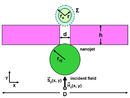
Following the scheme shown in Fig. 1, an incident beam, linearly p-polarized, namely with its magnetic vector perpendicular to the XY-plane is launched upwards, propagating in the Y direction. This choice is because p-polarization, in contrast with s-polarization, produces homogeneous eigenmodes, i. e. those which lead to extraordinary transmission of the subwavelength slit ValdiviaValero2010_1 ; ValdiviaValero2011_4 ; Jackson1999 ; Porto1999 ; Garcia2007 . The light beam incides on a dielectric cylinder of radius , which concentrates a nanojet near its back surface. The nanojet illuminates either the probe cylinder of radius when the slab in Fig. 1 does not exist; or, when the latter is present, this illumination is done on transmission of the nanojet through the slit, as seen in Fig. 1. The nomenclature followed to classify both localized surface plasmons (LSP) and whispering gallery modes (WGM) of the probe cylinders, as well as the resonances of the slit is: subscripts (i, j), i and j standing for their angular i-th and radial j-th orders, respectively. In the case of the supertransmission resonances of the slit alone the subscripts (u, v) will be used, u and v standing for their longitudinal u-th and transversal v-th orders.
In all cases the beam profile at frequency is Gaussian, with magnetic field distribution at its focal plane: , denoting the modulus amplitude, being the half width at half maximum (HWHM) of the beam, and representing its wavelength. In this way the beam has intensity and . The geometrical parameters of the cylinders and of the slit have been adjusted such that at the given illuminating wavelength , there is focalization of nanojets as well as excitation of morphology-dependent resonances of both the slit and the probe particle.
The physical quantities shown in the images of the configurations under study are the magnetic field , the electric field and the time-averaged energy flow . The curves presenting the nanojet intensity focused near the back surface of the cylinder, are obtained at the point where is maximum.
The light concentration either in or on the probe cylinder according to whether this is dielectric or metallic, is evaluated by integrating in a circle which coincides with the circle cross section of the probe cylinder of radius when this latter is dielectric, or in an annulus surrounding it of radii and when the probe cylinder is metallic, see Fig. 1. This stems from the fact that if the particle is dielectric the intensity transmitted by the slit, that couples to the particle WGM, is concentrated inside the cylinder; whereas when this nanoparticle is metallic, this transmitted intensity, coupled to a LSP, remains on the particle surface. On the other hand, the transmittance of the slab when the probe particle is not present is calculated on integration of in a circle of radius in void space which coincides with that of the probe cylinder cross section. In all cases these intensities are normalized to the maximum intensity of the incident Gaussian beam .
The time-averaged force on the probe cylinder is calculated by employing the Maxwell stress tensor (MST) Jackson1999 :
| (1) |
where the surface of integration surrounds the particle as seen in Fig. 1 and represents the outward unit normal. In our 2D geometry, is the circumference of radius , (see Fig. 1). .
In Eq. (1), and are the values of the fields and their complex conjugates, and denotes the electric permittivity and magnetic permeability of the surrounding medium, which in this work will be assumed to be vacuum.
The calculation with FEMLAB of the complex values and and of the real physical fields: and , are not straightforward. The details of the procedure have been given in ValdiviaValero2012_6
III Extraordinary transmission of a slit in presence of a nanojet. Excitation of a whispering gallery mode
III.1 Excitation of a WGM in a cylinder by nanojet focalization. Effects of coupling by supertransmission
In order to interpret the optical forces on the probe particles, we first discuss the fields resulting from the interaction. We begin dealing with the situation in which the slit is illuminated by a nanojet in the infrared region. The probe cylinder on the slit exit being dielectric. This makes it possible two processes of supertransmission enhancement: one due to the nanojet focused near the back surface of the dielectric cylinder of radius at the entrance of the aperture, and that resulting from the coupling between the light exiting the slit and the WGM excited in the probe cylinder of radius , (see Fig. 1).
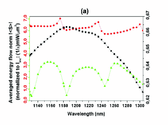
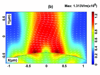
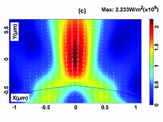
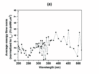
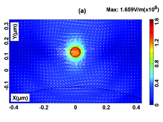
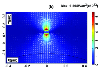
We first make a study of the fields and energy without the probe . Fig. 2(a) shows the black squared and green triangled curves which stand for the average energy flow, either when the Gaussian beam directly illuminates the slab without the presence of the nanojet, (peak at ), or when the incident light is focused as a nanojet near the back surface of a cylinder of radius placed at the slit entrance. The intensity at that point of the nanojet where it is maximum, without slab, is plotted as the red circle curve. The presence of the nanojet enhances the transmittance peak of the slit by a factor above 4 (at ), but erases the supertransmitted energy peak profile of the slit alone (compare the green triangle and the black square lines), manifesting the non resonant nature of the PNJ focusing process (see the red circle line). A detail of the nanojet alone, i.e. without slit nor cylinder, near the back surface of the cylinder is displayed both by its electric field distribution [see Fig. 2(b)] and by that of its energy flow [Fig. 2(c)], both maps clearly show the focalization process and the interesting vortex of electric field lines about the nanojet focus.
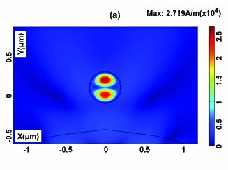
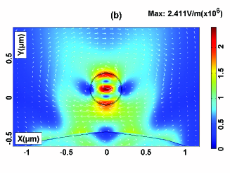
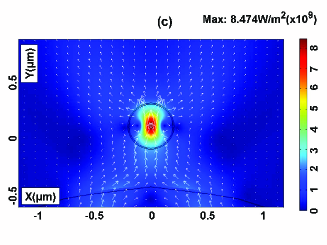
Next, the probe cylinder is placed above the without the presence of the slit. The light in the cylinder now concentrates in the form of a resonance, as shown by the dipolar map of the magnetic field norm in Fig. 3(a), . Consequently, the electric field distribution acquires a vortex pattern near the probe cylinder [cf. Fig. 3(b)] and, under this incident p-polarization, the light intensity from the nanojet is strongly localized within this cylinder [see Fig. 3(c)].
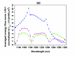
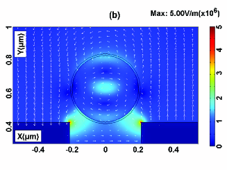
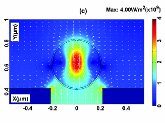
Figure 4(a) shows the average energy flow for all the configurations studied in this paper. The intensity of the nanojet localized in the cylinder of radius , without slit, is plotted in the blue curve with triangles down. The peaks of this curve coincide with those of the intensity peak point of the nanojet alone, [see the red curve with circles in Fig. 2(a)], but now enhanced by the resonant concentration due to the resonance at . As seen, this nanojet also enhances the energy asociated to the cylinder resonance by a factor of 10, [cf. the blue curve with triangles down in Fig. 4(a)], on comparing with the case of the resonant cylinder directly illuminated by the Gaussian beam without nanojet nor slit, (whose intensity integrated in the cylinder cross-section has a maximum at ; not shown here for brevity).
Concerning the nanojet focused in the slit with the cylinder at its exit, the transmitted intensity inside that cylinder against wavelength takes the form of the pink curve with rotated triangles of Fig. 4(a). This follows the trend of the intensity in that cylinder alone, (not shown here), modulated by that of the nanojet-slit system, as a result of the effect of nanojet focalization plus WGM resonance excitation. This shows a modest increase of transmitted intensity inside the particle (cf. the pink curve with rotated triangles) comparing with that of the nanojet large cylinder plus slit, without the particle, (cf. the green curve with triangles up). Nevertheless, the enhancement factor is now above 4 (at ) with respect to the transmitted intensity from the slit alone, [cf. black curve with squares in Fig. 2(a)].
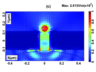
A detail of the spatial distributions of and at the optimum wavelength for largest transmitted intensity of the system constituted by the large cylinder, the subwavelength slit and the resonant probe cylinder, can be seen in Figs. 4(b) and 4(c), respectively, showing the vortex of the electric vector in the cylinder around the point of maximum intensity concentration. Also, the large charge localization in the corners of the slit is clearly observed. This will be seen to have important consequences for the optical forces on the cylinder.
III.2 Electromagnetic forces on a dielectric cylinder with a whispering gallery mode excited by a nanojet, either directly or on transmission through a subwavelength slit.
Next, we study the force that the electromagnetic fields of the nanojet transmitted through the slit exert on the probe cylinder placed at the slit exit.
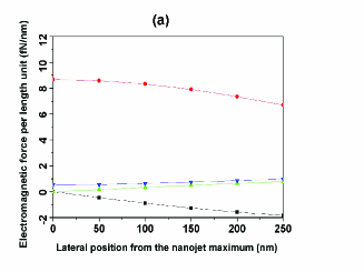
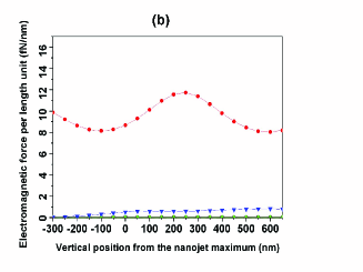
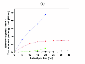
Figure 5(a) shows the variation in the X- and Y-components of this force when the particle moves horizontally from the peak point of the nanojet intensity map. In this case we assume no slit present. The particle, illuminated out of resonance, is gradually and increasingly attracted along the lateral direction by the gradient of intensity of the nanojet spatial distribution, and less and less pushed vertically, (cf. black squared and red circled curves, respectively). On the other hand, when the is excited, the particle is now slightly more and more laterally repelled from the peak intensity point of the nanojet map, (see the green up-triangle curve) and weakly, although increasingly and progressively, pushed in the vertical direction (cf. blue-down triangle curve).
Figure 5(b) presents the same quantities as those plotted in Fig. 5(a), but with the cylinder vertically moving upwards from the maximum intensity point of the nanojet spatial distribution. The absence or presence of the resonance in this particle is shown by the black square and green up-triangle curves, respectively. Obviously, due to the symmetry of the field intensity map around this axis, no horizontal force is exerted. In the vertical direction the particle is nevertheless fairly strongly pushed upwards, the force magnitude following an oscillatory behavior due to the interference pattern between the field exiting the slit and that reflected down by the cylinder. This push is weak if the WGM resonance is excited. In this latter case, under this -polarization illumination most of the near field is concentrated inside the particle, with little intensity outside. This leads to such weak optical forces on the resonant particle with the -polarized WGM in both Figs. 5(a) and 5(b).
It is worth remarking that these forces and induced by the nanojet on the particle are about 1000 and 10 times larger, respectively, than those from direct illumination of this probe cylinder by the Gaussian beam like in a conventional optical tweezer, (compare the above Figs. 5(a) and 5(b) with Figs. 5(a) and 5(b) of ValdiviaValero2012_6 ).
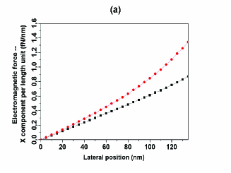
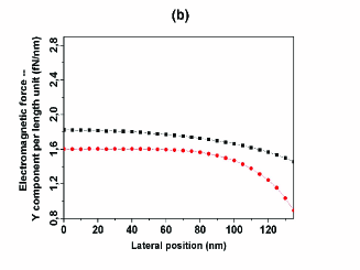
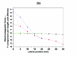
On the other hand, Figs. 6(a) and 6(b) show the X- and Y-components of the optical force exerted on the cylinder, placed on the exit of the subwavelength slit, by the electromagnetic field exiting it. A cylinder of radius is below the slit and forms a nanojet near its back surface. The particle laterally moves to the right approaching the slit edge. Each force Cartesian component is plotted for the cylinder being either out or in resonance. Now this particle is more and more horizontally attracted by the corners of the slit exit as it approaches them, independently of the absence or presence of the resonance [see the black square and red circle curves, respectively, in Fig. 6(a)], the horizontal force being stronger in resonance. Notwithstanding, the slit exerts a pushing vertical force on the cylinder which decreases as it moves to the slit corners, [cf. black squared and red circled curves, respectively, in Fig. 6(b)]. Then, the presence of the resonant in the particle causes the vertical push from the slit to decrease and the horizontal attraction to the slit corners to increase. The cause of this is the same as discussed in connection with Figs. 5(a) and 5(b) for -polarized illumination. However, as regards the horizontal force near the slit edge, the gradient force created around this edge by its concentration of charge, [see Figs. 4(b) and 4(c)], is responsible for the larger value of in resonance near this edge, as seen in Fig. 6(a). Thus, solely the field intensity gradient near the exit corners of the slit, (remember that in resonance under p-polarization the cylinder concentrates the intensity inside, leaving very little scattered energy in its surroundings), is the major factor concerning the interaction between the aperture and the resonant particle.
These forces induced by the nanojet on the particle through the slit are about 3 and 6 times larger than those from direct illumination of the slit by the Gaussian beam, i.e. without nanojet, (compare the above Figs. 6(a) and 6(b) with Figs. 5(a) and 5(b) of ValdiviaValero2012_6 ).
IV Extraordinary transmission of a subwavelength slit illuminated by a nanojet. Excitation of a localized surface plasmon.
IV.1 Excitation of a localized surface plasmon in a cylinder by nanojet focalization. Effects of coupling by supertransmission
We now deal with a subwavelength slit illuminated by a nanojet in the ultraviolet region when a metallic cylinder is at its exit. This produces two interacting processes of extraordinary transmission, or supertransmission, enhancement: one due to the coupling of the nanojet focused in the aperture with the excitation of its propagating eigenmodes, and that arising from the coupling of the field transmitted through the slit with the localized surface plasmon (LSP) excited on the metallic cylinder, ValdiviaValero2011_3 ; ValdiviaValero2012_6 . In order to analyze the optical force on the metallic particle, we first briefly discuss the distribution of fields and energy in this system.
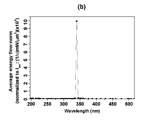
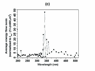
Now a cylinder of radius is placed below an slab and focuses, near its back surface, a nanojet which illuminates the slit. The calculations are done as described in Fig. 1. The rather smooth transmitted intensity with peak at that would be obtained if this slit were illuminated by the Gaussian beam without any nanojet, normalized to the maximum intensity (which was ), becomes, when the nanojet illuminates the slit, an oscillatory line, typical of nanojets, as seen in Fig. 7(a). Nevertheless, this configuration may render a slit-nanojet transmittance enhancement factor of about 4. Figure 7(b) represents the effect of light concentration in an cylinder of radius placed at 200nm from the back surface of the focusing cylinder when the slit is suppressed. The excited eigenmode energy concentrated on the surface of the cylinder is enhanced at by a factor about 33 due to the presence of the nanojet, [see Fig. 7(b)]. This effect is somewhat similar to that on the above studied particle, although now with a much stronger enhancement factor.
On the other hand, when the slit is also present as shown in Fig. 7(c), enhancement factors between 8 and 47 are obtained on ecitation of the LSP in the cylinder.
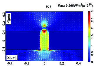
As illustrations, Figs. 8(a) and 8(b) present details of the effect of the nanojet near the cylinder. As seen, there is a skin depth effect at the illuminating wavelength due to the small size of this cylinder. This case corresponds to the largest peak in Fig. 7(b). The electric field and the time-averaged energy flow , respectively, are also shown. The nanojet is almost completely concentrated in the small metallic cylinder. Figs. 8(c) and 8(d) are details of and , respectively, for the configuration studied in Fig. 7(c) i. e. that of the nanojet-LSP coupling through the slit. The wavelength corresponds to the largest peak in Fig. 7(c), which practically remains the same as that of Fig. 7(b) when there is no slit. The hotspots in the slit edge, the nanojet focalization as well as the LSP excitation mechanisms are shown.
IV.2 Electromagnetic forces on a metallic cylinder with a localized surface plasmon excited by a nanojet, either directly or on transmission through a subwavelength slit.
We now are in position to analyze the optical forces induced by the nanojet and the slit on the metallic particle with excitation .
To this end, the excitation of the cylinder LSP eigenmode by focusing a nanojet on it, is studied. Figure 9(a) shows the behavior of the X- and Y-components of the force on this metallic particle as it progressively moves to the right in absence of the slit. This force is due to only the field of the nanojet scattered by the particle. When the particle is not resonant, the forces along the X and Y directions are very weak, of the order of and for the horizontal force (black curve with squares) and for the vertical force (red curve with circles), respectively. In resonance the horizontal force is still very weak, but the vertical component is strong and atractive. On the other hand, as the cylinder moves upwards along the nanojet axis, as shown in Fig. 9(b), no transversal force appears (black squared and green up-triangled curves, respectively) as it should, but differences in the vertical force arise depending on the absence or the presence of a LSP resonance. This vertical force is very small in absence of LSP excitation: about , whereas it is attractive and oscillating with distance, and of the order of when the LSP resonance of the cylinder is excited, this oscillation is due to the interference pattern between the nanojet inciding on the metallic particle and the field that the latter scatters backward.
Notice the remarkable pulling nature of this vertical force, which converts the cylinder in a photonic tractor JuanjoNat ; Chinos ; Novitski for certain plasmonic small particles. This contrasts with the repulsive obtained in Cui2008 on an particle in resonance. However, if one doubles its radius making it of , then this force becomes repulsive due to its larger scattering cross section. We do not show this here for brevity.
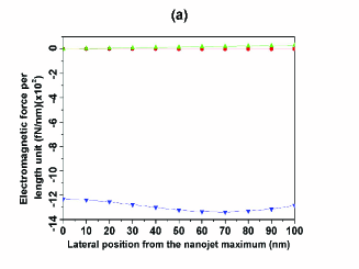
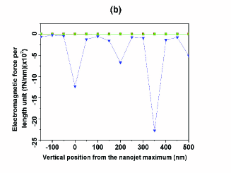
Finally, the presence of the slit illuminated by the nanojet is analized concerning the optical forces acting on the cylinder. Once again, the excitation of a LSP resonance largely affects these forces, but due to -polarized illumination, it has consequences opposite to those of the WGM excitation in a dielectric particle, (cf. Figs. 10(a) and 10(b) for the X- and Y-components of this optical force, respectively). Black square and red circle curves in Fig. 10(a) stand for the cases of absence and presence of LSP resonance in the cylinder, respectively. They show that the plasmonic resonance enhances the lateral force, which progressively attracts the particle towards the corners as it approaches it in its displacement. The vertical force, plotted with the same color code in Fig. 10(b), behaves in a more complex way. This being slightly attractive when the cylinder is non resonant (values of order ). However, in presence of resonance this vertical force is, though, repulsive in the central region of the slit exit, becoming attractive near its corners (red circled curve). These tendencies can be increased by locating the cylinder inwards the slit exit, as noticed by the green up-triangles and blue down-triangles curves of both Figs. 10(a) and 10(b). [Values of order for the green up triangles curve (non resonant cylinder) in Fig. 10(b)].
In any case, the forces induced by the nanojet on the particle through the slit are about 10 times larger than those from direct illumination of the slit by the Gaussian beam without nanojet, (compare the above Figs. 10(a) and 10(b) with Figs. 11(a) and 11(b) of ValdiviaValero2012_6 ).
V Discussion and conclusions
We have made a study on the photonic forces on nanoparticles near a subwavelength slit illuminated by a nanojet. We have performed comparisons of the force on the particles either in or out of their Mie resonance excitation. The study has been done in 2D, so that these objects are cylinders and the transmission modes of the slit are excited by p-polarized illumination. However, we believe that these results also hold for spheres in 3D, aside of polarization effects.
We have proven that whereas the morphological resonance of the slit, causing supertransmission, enhances the fields surrounding the probe cylinders and hence the optical forces exerted upon them, the excitation of the probe particle resonance has a different effect on these forces, according to whether the cylinder is dielectric or metallic.
The photonic force on the probe particle dependens on the field surrounding it. Thus WGMs in dielectric nanocylinders under p-polarization, (which is the one at which supertransmission exists in 2D), have no much effects on the optical force. Its strength may weaken due to the low intensity distribution in the near field region of this particle. In this connection, it must be remarked that the electromagnetic force on dielectric cylinders is however enhanced under s-polarization illumination AriasGonzalez2002 ; then the WGM extends to the near field outside the cylinder.
On the other hand, LSPs in metallic nanocylinders give rise to localized field energy enhancement on the cylinder surface; this strengthes the optical force. In contrast with illumination by only a PNJ, the presence of a subwavelength slit enriches the effect of the electromagnetic forces. Whereas such a a small metallic particle resonantly illuminated by a nanojet, suffers an attractive vertical force which makes the nanojet forming cylinder to behave as a photonic tractor, the additional presence of a subwavelength aperture may change the sign of this force thus transforming it to repulsive, depending on the lateral position of the cylinder.
For any cylinder, whether dielectric or metallic, we observe that illuminating the slit with a nanojet increases the magnitude of the optical forces on the particle by a factor between 3 and 10 compared with illumination of the slit with a Gausian beam. On the other hand, the gradient horizontal force induced by a nanojet in a dielectric particle is a few orders of magnitude larger than that of a Gaussian beam of a conventional optical tweezer.
These results should stimulate experiments with PNJs on slits since they are the result of focusing by microparticles, and their highly localized intensity at the subwavelength scale present an ideal means to spatially control the mechanical action on nanoobjects.
Acknowledgements
Work supported by the Spanish MEC through FIS2009-13430-C02-C01 and Consolider NanoLight (CSD2007-00046) research grants, FJVV is supported by the last grant.
References
- (1) A. Ashkin, J. M. Dziedzic, J. E. Bjorkholm, and S. Chu, “Observation of a single-beam gradient force optical trap for dielectric particles,” Opt. Lett. 11, 288–290 (1986).
- (2) T. T. Perkins, D. E. Smith, R. G. Larson, and S. Chu, “,Stretching of a single tethered polymer in a uniform flow” Science 268, 83–87 (1990).
- (3) H. Yin, M. D. Wang, K. Svoboda, R. Landick, S. M. Block, and J. Gelles, “Transcripting against an applied force,” Science 270, 1653–1657 (1995).
- (4) Y. Liu, G. J. Sonek, M. W. Berns, and B. J. Tromberg, “Physiological monitoring of optically trapped cells: assessing the effects of confinement by 1,064nm laser tweezers using microfluorometry,” Biophys. J. 71, 2158–2167 (1996).
- (5) K. Okamoto and S. Kawata, “Radiation force exerted on subwavelength particles near a nanoaperture,” Phys. Rev. Lett. 83, 4534–4537 (1999).
- (6) P. Chaumet and M. Nieto-Vesperinas, “Time-averaged total force on a dipolar sphere in an electromagnetic field,” Opt. Lett. 25, 1065–1067 (2000).
- (7) M. Nieto-Vesperinas, P. C. Chaumet, and A. Rahmani, “Near-field photonic forces,” Phil. Trans. R. Soc. Lond. A 362, 719–737 (2004).
- (8) K. Dholakia, P. Reece, and M. Gu, “Optical micromanipulation,” Chem. Soc. Rev. 37, 42–55 (2008).
- (9) M. L. Juan, R. Gordon, Y. Pang, F. Eftekhari, and R. Quidant, “Self-induced back-action optical trapping of dielectric nanoparticles,” Nat. Phys. 5, 915–919 (2009).
- (10) M. L. Juan, M. Righini, and R. Quidant, “Plasmon nano-optical tweezers,” Nat. Photonics 5, 349–356 (2011).
- (11) M. Burns, J.M. Fournier and J. A. Golovchenko, “Optical binding,” Phys. Rev. Lett. 63 1233–1236 (1989).
- (12) P. C. Chaumet and M. Nieto-Vesperinas, “Optical binding of particles with or without the presence of a flat dielectric surface,” Phys. Rev. B 64, 035422 (2001).
- (13) K. Dholakia and P. Zemánek, Colloquium: “Gripped by light: Optical binding”, Rev. Mod. Phys. 82, 1767–1791 (2010).
- (14) F.J. Valdivia-Valero and M. Nieto-Vesperinas, “Optical forces on cylinders near subwavelength slits: effects of extraordinary transmission and excitation of Mie resonances,” Opt. Exp 20, 13369–13389 (2012).
- (15) F. J. García-Vidal, L. Martín-Moreno, T. W. Ebbesen, and L. Kuipers, “Light passing through subwavelength apertures,” Rev. Mod. Phys. 82, 729–787 (2010).
- (16) T. W. Ebbesen, H. J. Lezec, H. F. Ghaemi, T. Thio, and P. A. Wolff, “Extraordinary optical transmission through sub-wavelength hole arrays,” Nature 391, 667–669 (1998).
- (17) N. García, V. Celli, and M. Nieto-Vesperinas, “Exact multiple scattering of light from surfaces,” Opt. Commun. 30, 279–281 (1979).
- (18) A. García-Martín, J. A. Torres, J. J. Sáenz, and M. Nieto-Vesperinas, “Transition from diffusive to localized regimes in surface-corrugated waveguides,” Appl. Phys. Lett. 71, 1912–1914 (1997).
- (19) N. Garcia and M. Nieto-Vesperinas, “Near-field optics inverse reconstruction of reflective surfaces,” Opt. Lett. 18, 2090-2092 (1993).
- (20) J. Ripoll, V. Ntziachristos, J.P. Culver, C.N. Pattanayak and M. Nieto-Vesperinas, “Recovery of optical parameters in multiply layered media: theory and experiments,” J. Opt. Soc. Am. 18, 821-830 (2001).
- (21) A. Degiron, H. J. Lezec, N. Yamamoto, and T. W. Ebbesen, “Optical transmission properties of a single subwavelength aperture in a real metal,” Opt. Commun. 239, 61–66 (2004).
- (22) H. Lezec and T. Thio, “Diffracted evanescent wave model for enhanced and suppressed optical transmission through subwavelength hole arrays,” Opt. Express 12, 3629–3651 (2004).
- (23) A. Alu, F. Bilotti, N. Engheta, and L. Vegni, “Metamaterial covers over a small aperture,” IEEE Trans. Antennas Propag. 54, 1632–1643 (2006).
- (24) H. J. Lezec, A. Degiron, E. Devaux, R. A. Linke, L. Martín-Moreno, F. J. García-Vidal, and T. W. Ebbesen, “Beaming light from a subwavelength aperture,” Science 297, 820–822 (2002).
- (25) F. J. García-Vidal, E. Moreno, J. A. Porto, and L. Martín-Moreno, “Transmission of light through a single rectangular hole,” Phys. Rev. Lett. 95, 103901 (2005).
- (26) E. Di Gennaro, I. Gallina, A. Andreone, G. Castaldi, and V. Galdi, “Experimental evidence of cut-wire-induced enhanced transmission of transverse-electric fields through sub-wavelength slits in a thin metallic screen,” Opt. Express 18, 26769–26774 (2010).
- (27) J. R. Arias-González and M. Nieto-Vesperinas, “Near-field distributions of resonant modes in small dielectric objects on flat surfaces,” Opt. Lett. 25, 782–784 (2000).
- (28) J. R. Arias-González and M. Nieto-Vesperinas, “Resonant near-field eigenmodes of nanocylinders on flat surfaces under both homogeneous and inhomogeneous lightwave excitation,” J. Opt. Soc. Am. A 18, 657–665 (2001).
- (29) V. N. Astratov, J. P. Franchak, and S. P. Ashili, “Optical coupling and transport phenomena in chains of spherical dielectric microresonators with size disorder,” Appl. Phys. Lett. 85, 5508–5510 (2004).
- (30) Z. Chen, A. Taflove, and V. Backman, “Highly efficient optical coupling and transport phenomena in chains of dielectric microspheres,” Opt. Lett. 31, 389–391 (2006).
- (31) S. Deng, W. Cai, and V. N. Astratov, “Numerical study of light propagation via whispering gallery modes in microcylinder coupled resonator optical waveguides,” Opt. Express 12, 6468–6480 (2004).
- (32) S. V. Boriskina, “Theoretical prediction of a dramatic Q-factor enhancement and degeneracy removal of whispering gallery modes in symmetrical photonic molecules,” Opt. Lett. 31, 338–340 (2006).
- (33) S. A. Maier and H. A. Atwater, “Plasmonics: localization and guiding of electromagnetic energy in metal/dielectric structures,” J. Appl. Phys. 98, 011101 (2005).
- (34) S. E. Sburlan, L. A. Blanco, and M. Nieto-Vesperinas, “Plasmon excitation in sets of nanoscale cylinders and spheres,” Phys. Rev. B 73, 035403 (2006).
- (35) S. A. Maier, Plasmonics: Fundamentals and Applications (Springer Science + Business Media LLC, New York, 2007).
- (36) M. Pelton, J. Aizpurua, and G. Bryant, “Metal-nanoparticle plasmonics,” Laser Photon. Rev. 2, 136–159 (2008).
- (37) F.J. Valdivia-Valero and M. Nieto-Vesperinas, “Whispering gallery mode propagation in photonic crystals in front of subwavelength slit arrays. Interplay with extraordinary transmission,” Opt. Commun. 284, 1726–1733 (2011).
- (38) F. J. Valdivia-Valero and M. Nieto-Vesperinas, “Resonance excitation and light concentration in sets of dielectric nanocylinders in front of a subwavelength aperture. Effects on extraordinary transmission,” Opt. Express 18, 6740–6754 (2010).
- (39) F. J. Valdivia-Valero and M. Nieto-Vesperinas, “Propagation of particle plasmons in sets of metallic nanocylinders at the exit of subwavelength slits,” J. Nanophotonics 5, 053520 (2011).
- (40) Z. Chen, A. Taflove, and V. Backman, “Photonic nanojet enhancement of backscattering of light by nanoparticles: a poetential novel visible-light ultramicroscopy technique,” Opt. Expr. 12, 1214–1220 (2004).
- (41) X. Li, Z. Chen, A. Taflove, and V. Backman, “Optical analysis of nanoparticles via enhanced backscattering facilitated by 3-D photonic nanojets,” Op. Expr. 13, 526–533 (2005).
- (42) Z. Chen, A. Taflove, X. Li, and V. Backman, “Superenhanced backscattering of light by nanoparticles,” Opt. Lett. 31, 196–198 (2006).
- (43) A. Heifetz, S. Kong, A. V. Sahakian, A. Taflove, and V. Backman, “Photonic Nanojets,” j. Comp. Tecn 6, 1979–1992 (2009).
- (44) F. J. Valdivia-Valero and M. Nieto-Vesperinas, “Enhanced transmission through subwavelength apertures by excitation of particle localized plasmons and nanojets,” Opt. Express 19, 11545–11557 (2011).
- (45) V. Itagi and W. A. Challener, “Optics of photonic nanojets,” J. Opt. Soc. Am. A 22, 2847–2858 (2005).
- (46) A. Heifetz, J. J. Simpson, S. C. Kong, A. Taflove, and V. Beckman, “Subdiffraction optical resolution of a gold nanosphere located within the nanojet of a Mie-resonant dielectric microsphere,” Opt. Expr. 15, 17334–17342 (2007).
- (47) A. Heifetz, K. Huang, A. V. Sahakian, X. Li, A. Taflove, and V. Backman, “Experimental confirmation of backscattering enhancement induced by a photonic jet,” Appl. Phys. Lett. 89, 221118 (2006).
- (48) X. Cui, D. Erni, and C. Hafner, “Optical forces on metallic nanoparticles induced by a photonic nanojet,” Opt. Express 16, 13560–13568 (2008).
- (49) M. K. Chin, D. Y. Chu, and S. T. Ho, “Estimation of the spontaneous emission factor for microdisk lasers via the approximation of whispering gallery modes,” J. App. Phys. 75, 3302–3307 (1994).
- (50) J. R. Arias-González, M. Nieto-Vesperinas, and M. Lester, “Modeling photonic force microscopy with metallic particles under plasmon eigenmode excitation,” Phys. Rev. B 65, 115402 (2002).
- (51) P. C. Chaumet and M. Nieto-Vesperinas, “Coupled dipole method determination of the electromagnetic force on a particle over a flat dielectric substrate,” Phys. Rev. B 61, 14119–14127 (2000).
- (52) P. C. Chaumet and A. Rahmani, “Electromagnetic force and torque on magnetic and negative-index scatterers,” Opt. Express 17, 2224–2234 (2009).
- (53) M. Nieto-Vesperinas, J. J. Sáenz, R. Gómez-Medina, and L. Chantada, “Optical forces on small magnetodielectric particles,” Opt. Express 18, 11428–11443 (2010).
- (54) L. A. Blanco and M. Nieto-Vesperinas, “Optical forces near subwavelength apertures in metal discs,” J. Opt. A: Pure Appl. Opt. 9, S235–S238 (2007).
- (55) S. Albaladejo, M. I. Marqués, M. Laroche, and J. J. Sáenz, “Scattering forces from the curl of the spin angular momentum of a light field,” Phys. Rev. Lett. 102, 113602 (2009).
- (56) J. L. García-Pomar and M. Nieto-Vesperinas, “Waveguiding, collimation and subwavelength concentration in photonic crystals,” Opt. Express 13, 7997–8007 (2005).
- (57) P. B. Johnson and R. W. Christy, “Optical constants of the noble metals,” Phys. Rev. B 6, 4370–4379 (1972).
- (58) E. D. Palik, Handbook of Optical Constants of Solids (Academic Press, New York, 1998)
- (59) H. Rigneault, J. Capoulade, J. Dintinger, J. Wenger, N. Bonod, E. Popov, T. W. Ebbesen, and P. F. Lenne, “Enhancement of single-molecule fluorescence detection in subwavelength apertures,” Phys. Rev. Lett. 95, 117401 (2005).
- (60) J. D. Jackson, Classical Electrodynamics (Wiley, New York, 1999).
- (61) J. A. Porto, F. J. García-Vidal, and J. B. Pendry, “Transmission resonances on metallic gratings with very narrow slits,” Phys. Rev. Lett. 83, 2845–2848 (1999).
- (62) N. García and M. Nieto-Vesperinas, “Theory of electromagnetic wave transmission through metallic gratings of subwavelenght slits,” J. Opt. A: Pure Appl. Opt. 9, 490–495 (2007).
- (63) J.J. Saenz, “Laser tractor beams,” Nature Phtonics 5, 514-515 (2011).
- (64) J. Chen, J. Ng, Z. Lin and C. T. Chan, “Optical pulling force,” Nature Phtonics 5, 531-534 (2011).
- (65) A. Novitsky, Ch-Wei Qiu, and H. Wang, “Single gradientless light beam drags particles as tractor beams,” Phys. Rev. Lett.107, 203601 (2011).