An all-optical event horizon in an optical analogue of a Laval nozzle
Abstract
Exploiting the fact that light propagation in defocusing nonlinear media can mimic the transonic flow of an equivalent fluid, we demonstrate experimentally the formation of an all-optical event horizon in a waveguide structure akin to a hydrodynamic Laval nozzle. The analogue event horizon, which forms at the nozzle throat is suggested as a novel platform for analogous gravity experiments.
pacs:
42.65.-k, 47.40.Hg, 47.60.Kz, 07.05.FbEvent horizons are well known in the context of astrophysics and cosmology. Less known are the analogy between an astrophysical event horizon and the sonic horizon in transonic fluid flow, and the prediction that a thermal spectrum of sound waves should be emitted from a sonic horizon, in analogy with Hawking radiation Unruh . These analogies set the stage for attempts to create laboratory black hole analogues, involving various physical scenarios, from water flowing in a channel to the acceleration of a superfluid to nonlinear optical experiments Rousseaux1 ; Philbin ; Marino ; Recati ; Lahav ; Rousseaux2 ; Belgiorno ; Fouxon ; Weinfurtner . We have recently proposed an alternative approach to analogue gravity experiments – an all-optical experiment based on laser light propagation in a distinctive nonlinear waveguide, which is analogous to a Laval nozzle (a well-known device in the context of aerodynamics). This approach has two great advantages over previous experiments: The attainment of supersonic velocities is very easy, and the analogue of Hawking radiation has a unique optical signature, which can be readily detected Fouxon . The analogy is based on the realization that under certain conditions light can ”flow” through certain types of media in a fashion reminiscent of actual fluid flow. A prime example is a laser beam propagating through a Kerr-type nonlinear medium, which is usually described analytically by the Non-Linear Schrödinger equation Zakharov . The latter can be mapped, through the Madelung transformation Madelung , to a pair of coupled equations for the amplitude and phase, which have the form of continuity and Euler equations for an equivalent fluid Marino ; Fouxon ; Madelung ; Marburger ; El ; Fleischer ; Jia ; Barsi , which may be called ”luminous fluid”:
| (1) | |||
Eqs. (1) describe the evolution of the complex amplitude as the light propagates along the z axis with the wave vector . Here is the light intensity, and the transverse component of the wave-vector, , plays the role of velocity. The coordinate z plays the role of time, is equivalent to the mass of a particle, and the spatially inhomogeneous refraction index assumes the role of a potential, . The nonlinear term is due to the Kerr effect. Thus incident light, which propagates at an angle relative to the z axis is mapped onto a fluid with a finite transverse velocity, and a change of that angle corresponds to acceleration of the fluid. This approach has proved to be an extremely powerful one when applied to the problem of coherent tunneling Fleurov ; Dekel1 ; Dekel2 ; Barak ; Wan ; Cohen . It has also been used to model dispersive shock waves that appear when the nonlinearity is repulsive (i.e. self-defocusing, ), and consequently an equivalent real sound velocity can be defined El ; Fleischer ; Jia ; Barsi ; Hakim ; Leszczyszyn ; Gladush . Our proposal for an optical analogue of the Laval nozzle uses a similar approach,Fouxon ; Fleurov2 and shows that when the light is confined by a properly shaped channel (i.e. waveguide), represented by the transverse potential , it may propagate transversally in a way that resembles the accelerating transonic flow of the equivalent, luminous fluid. Thus low-incidence, (i.e. ”subsonic”) laser light is predicted to accelerate, (i.e. change its propagation direction) while traversing the nozzle, reaching a critical velocity, which is equivalent to the sound velocity in a real fluid, at the nozzle throat, and exiting the nozzle at a ”supersonic” velocity. While the notion that light propagation in nonlinear media can mimic the flow of an equivalent fluid is not new, the equivalent of transonic acceleration in an optical analogue of a Laval nozzle has never been observed before in an actual experiment, and is demonstrated here for the first time.
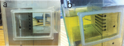
We study the flow of luminous liquid through an optical Laval nozzle experimentally by launching a continuous wave laser beam into an appropriately shaped waveguide with reflective walls, filled with a Kerr-type defocusing nonlinear material. The experimental challenge here is to create conditions of steady flow with a subsonic input velocity. Since the velocity is (where is the -component of the wave vector) and the sound velocity is , the above input conditions imply a small input angle of the beam and a high nonlinearity and/or input intensity (Note that, for a given angle, low and high intensities correspond to supersonic and subsonic flow, respectively). However, an unavoidable consequence of these conditions is strong self-defocusing of the beam, and as a result the wave packet, which traverses the nozzle is an expanding ”droplet” of liquid, with a tendency of the power density in the cavity to decrease with increasing input power. Furthermore, while the peak intensity of the droplet may correspond to subsonic flow, it is always surrounded by supersonic flow (in contrast to the usual case in hydrodynamics), and when confined to a Laval nozzle such as the one discussed in Ref. Fouxon, , the fluid flows from the throat towards both sides of the nozzle. It is thus impossible to generate the steady sonic background flow conditions stipulated by the theory in a simple waveguide with a convergent-divergent cross-section formed by two convex walls. To circumvent this problem we use an alternative waveguide design, based on a light-pipe of circular cross-section drilled in an aluminum block, with a groove of triangular cross-section, cut along the side of the channel, acting as the divergent section of the nozzle (see Fig. 1). The total length of each light pipe is = 67 mm, and the groove extends over the second half of this length. This design is intended to ”trap” the expanding beam and confine it in a homogeneous, high-density and low-velocity mode, thus preparing it for ejection through the groove, and is akin to the configuration of a rocket engine: a high-pressure gas is first loaded into a combustion chamber, and is then expelled through the nozzle. The aluminum block, with several nozzles of different diameters, aperture sizes and groove opening angles, is enclosed in a plexiglass cell with glass windows, which is sealed and filled with iodine-doped ethanol. The nonlinear index variations result from optical absorption by the iodine, which in turn leads to thermally-induced changes of the index of refraction – a non-local nonlinearity, which slightly washes out the thermal gradients Barsi . The nonlinearity can be expressed, in terms of the nonlinearly-induced refractive index change , as , where is the linear refractive index of the material Barsi . The corresponding dimensionless sound velocity is then , meaning that the input beam is subsonic for . We use a continuous-wave frequency-doubled YAG laser (532 nm), and focus the beam to a 0.5 mm waist at the input of a waveguide. The input power is varied by means of the laser controller, in order to avoid thermal effects in variable-density filters. Images of the exit plane of the waveguide are recorded by means of a CCD camera. In all cases images were acquired after stabilization of the thermal gradients.
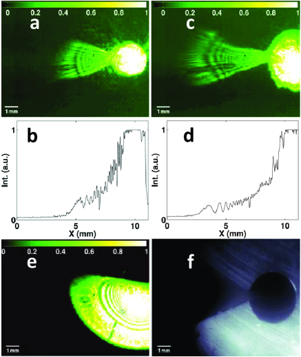
Figure 2 presents images of the exit plane of two of the waveguides, and the corresponding power density cross-sections along the nozzle axis, for an input power (2 Watts) that is sufficiently high to completely fill the waveguides (at an iodine concentration of 40 ppm). Figure 2(a) shows a 2 mm diameter waveguide, and Fig. 2(c) shows a 3 mm diameter waveguide, both having a 0.5 mm opening (i.e. nozzle throat). Figures 2(b) and 2(d) are the power density cross-sections corresponding to Figs. 2(a) and 2(c), respectively, obtained by summation over 12 CCD lines at the center of each nozzle. Figure 2(e) shows the free expansion of the beam when it propagates outside the waveguide structure, and Fig. 2(f) shows a reference image of the 3 mm diameter waveguide, obtained with incoherent light and with the laser beam blocked. Figures 2(a)-(d) clearly show the jets of luminous liquid ejected from the nozzles as the beam propagates through the waveguides. Note that the jets extend farther than the edge of the beam undergoing free expansion (Fig. 2(e) – A detailed analysis is presented in Fig. 3). Furthermore, there is a sharp drop in the density as the jet exits the nozzles, which is clearly seen in the images and in the power density cross-sections. This demonstrates that the luminous liquid is accelerating at the nozzle throat rather than gradually expanding through the opening. Finally, while the confined beam propagates along the waveguide walls at a very slow (i.e. subsonic) velocity, the following analysis shows that the jet of luminous liquid is indeed supersonic: The dimensionless velocity of the jet outside the waveguide is first calculated from its extension in the transverse direction, deduced from the images. The relation is simply , where is the transverse distance from the nozzle throat to the edge of the jet, and is the distance along the axis that the same part of the jet has propagated by the time it reached the exit plane. This velocity should be compared to the local sound velocity, which can be estimated by analyzing the light intensity distribution in the exit plane and the rate of expansion of the freely-expanding (i.e. self-defocusing) beam. The latter, deduced from Fig. 2(e), allows us to calculate and the corresponding sound velocity at the input. The former in turn allows us to deduce the sound velocity, which corresponds to the lower density of the jet, taking into account the expansion of the beam in the light-pipe, the relative intensities of the jet and inside the light-pipe, and measured losses. This calculation gives a local sound velocity in the jet on the order of or less, meaning that the local Mach number is 100. This clearly establishes that the luminous liquid undergoes transonic acceleration and forms a ”sonic” horizon as it expands through the nozzle.
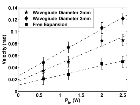
In Fig. 3 the dimensionless velocities () of the jets emanating from the 3 mm and 2 mm nozzles are plotted as a function of the input intensity, for a fixed iodine concentration. Also shown is the velocity at the envelope of the freely-expanding beam, which we estimate as (In this case we measure from the center of the beam, which we determine from low-intensity measurements; This velocity corresponds to the asymptotic expansion angle, obtained for , i.e. when the propagation distance is much longer than the characteristic defocusing distance, and is a reasonable estimate for intensities 1 Watt). Figure 3 clearly shows that the velocity of the jet is higher than that of the freely-expanding beam throughout the experimental intensity range, in spite of the fact that the initial conditions for the free expansion involve higher pressures (the equivalent of pressure in a luminous liquid is ). On the other hand Fig. 3 shows that the jet emanating from the 2 mm waveguide is slower than that ejected from the 3 mm nozzle, although, for a given input intensity, the pressure in the latter is supposed to be lower. This discrepancy can result from the fact that the opening in the 2 mm waveguide subjects a larger angle, resulting in a less directional jet (compare Figs. 2(a) and 2(c)). We also measure higher losses (due to scattering and absorption) in the smaller waveguide, so in fact the power densities in the two waveguides are comparable. Finally, the non-locality of the nonlinearity may have a stronger effect on the 2 mm waveguide.
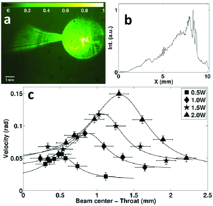
Measurements at lower intensities illustrate another regime of operation of the nozzles. Figure 4(a) shows an image of the 3 mm waveguide for self-defocusing (i.e. beam expansion) that is not sufficiently strong to completely fill it (an input power of 2 Watts and an iodine concentration of only 20 ppm). Figure 4(b) shows the corresponding power density cross-sections along the nozzle axis. In order to produce the jet seen in Fig. 4(a) the nozzle throat had to be displaced (horizontally) relative to the beam axis. Figure 4(c) shows the dependence of the jet velocity on the displacement and the input power. Note that as the input power increases the optimum acceleration is obtained when the beam axis is moved farther away from the throat (at an input power of 2 Watts the beam axis is then near the center of the waveguide). A comparison of the data in 4(c) with the divergences of the freely-expanding beam, measured separately for the same input powers, shows that optimum acceleration at the nozzle is obtained when the envelope of the freely-expanding beam coincides with the nozzle throat halfway through the waveguide (i.e. at ). Under these conditions the luminous liquid entering the nozzle is already supersonic, and is accelerated further in the divergent section of the nozzle. The smooth power density cross-section shown in Fig. 4(b) supports this interpretation (compare this to the sharp density gradients at the throat in Fig. 2). In this case the nozzle operates in a regime that is not typical of a Laval nozzle, though.
In conclusion, we demonstrate experimentally, for the first time, the transonic acceleration of a luminous liquid through an optical analogue of a Laval nozzle. The analogue of a sonic event horizon, which forms at the nozzle throat, lends itself to studies of classical (and possibly quantum) fluctuations that are akin to Hawking radiation Fouxon . Compared to other experiments and proposals for ”analogue gravity” Rousseaux1 ; Philbin ; Marino ; Recati ; Lahav ; Rousseaux2 ; Belgiorno ; Weinfurtner , our experiment has the advantage that it allows easy generation of supersonic flow conditions. While the nonlinearity length in our experiment is sufficiently short to give way to fluctuations with a linear dispersion relation,Fouxon the challenge is to create an equivalent Hawking temperature that is high enough to measure experimentally. Note that this is not a real temperature, but it rather a constraint on the minimum light intensity (and sound velocity) required in the waveguide: As explained in Ref. Fouxon, , the ratio of amplitudes of the two parts of a classical fluctuation with wave vector – the part which is carried away with the supersonic flow (i.e. ”falls” into the black hole) and the part which penetrates into the subsonic region (i.e. ”escapes” from the black hole), is , where is a characteristic length scale of the nozzle and is the sound velocity at the throat. This ratio needs to be of order unity so that both parts would be observed in the experiment, and allow direct measurement of the Hawking temperature . The same condition can also be written as , where and are characteristic length scales of the horizon and the fluctuations, respectively. In the experiment described here is on the order of a few meters ( m, , while must be on the order of a few centimeters (the length of the cavity). This may still allow observation of the part of a fluctuation which is carried away with the supersonic flow, but the part which penetrates into the subsonic region will most likely be submerged in noise. Therefore must be decreased by two orders of magnitude. Note, however, that for given input intensity and nonlinear coefficient the factor in the expression for grows like . We therefore estimate that an order of magnitude smaller cavity will be sufficient for observing both parts of a straddled classical fluctuation. The requirement for a slow rate of acceleration can be met by a refined, smoother waveguide cross-section, compared to the rudimentary prototype that we have used here for demonstration purposes.
We thank Mr. G. Elazar for his technical support. This research was supported by the US-Israel Binational Science Foundation and by the Israel Science Foundation.
References
- (1) W. G. Unruh, Phys. Rev. Lett. 46, 1351 (1981).
- (2) G. Rousseaux et al., New J. Phys. 10, 053015 (2008).
- (3) T.G. Philbin et al., Science 319, 1367 (2008).
- (4) F. Marino, Phys. Rev. A 78, 063804 (2008).
- (5) A. Recati, N. Pavloff, and I. Carusotto, Phys. Rev. A 80, 043603 (2009).
- (6) O. Lahav et al., Phys. Rev. Lett. 105, 240401 (2010).
- (7) G. Rousseaux et al., New J. Phys. 12, 095018 (2010).
- (8) F. Belgiorno et al., Phys. Rev. Lett. 105, 203901 (2010).
- (9) I. Fouxon et al., Europhys. Lett. 92, 14002 (2010).
- (10) S. Weinfurtner et al., Phys. Rev. Lett. 106, 021302 (2011).
- (11) V. E. Zakharov and A. B. Shabat, Sov. Phys. JETP 34, 62 (1972).
- (12) E. Madelung, Z. Phys. 40, 322 (1927).
- (13) J. H. Marburger, Prog. Quant. Electron. 4, 35 (1975).
- (14) G. A. El et al., Physica D 87, 186 (1995).
- (15) W. Wan, S. Jia, J. W. Fleischer, Nat. Phys. 3, 46 (2007).
- (16) S. Jia, W. Wan, J. W. Fleischer, Phys. Rev. Lett. 99, 223901 (2007).
- (17) C. Barsi et al., Opt. Lett. 32, 2930 (2007).
- (18) V.Fleurov and A.Soffer, Europhys. Lett. 72, 287 (2005).
- (19) G. Dekel et al., Phys. Rev. A 75, 043617 (2007).
- (20) G. Dekel et al., Phys. Rev. A 81, 063638 (2010).
- (21) A. Barak et al., Phys. Rev. Lett. 100, 153901 (2008).
- (22) W. J. Wan, S. Muenzel, and J. W. Fleischer, Phys. Rev. Lett. 104, 073903 (2010).
- (23) E. Cohen et al., arXiv: 1107.0627.
- (24) V. Hakim, Phys. Rev. E 55, 2835 (1997).
- (25) A. M. Leszczyszyn et al., Phys. Rev. A 79, 063608 (2009).
- (26) Yu. G. Gladush et al., Phys. Rev. A 75, 033619 (2007).
- (27) V. Fleurov and R. Schilling, Phys. Rev. A85, 045602 (2012).