A mechanism to pin skyrmions in chiral magnets
Abstract
We propose a mechanism to pin skyrmions in chiral magnets by introducing local maximum of magnetic exchange strength, which can be realized in chiral magnetic thin films by engineering the local density of itinerate electrons. Thus we find a way to artificially control the position of a single skyrmion in chiral magnetic thin films. The stationary properties and the dynamical pinning and depinning processes of an isolated skyrmion around a pinning center are studied. We do a series of simulations to show that the critical current to depin a skyrmion has linearly dependence on the pinning strength. We also estimate the critical current to have order of magnitude .
pacs:
73.43.Cd, 75.10.Hk, 72.25.-bI introduction
Vortices have long been the standard topological objects in condensed matter physics. They are topologically stable to perturbations, localized in space, and they can be moved, created or annihilated. In recent years, another kind of topological object “skyrmion” is observed in chiral magnets. A skyrmion is a configuration of three dimensional unit vectors in a two dimensional space which wraps around the unit sphere once when we move from the center of the space to infinity. Skyrmions were first proposed in high energy physics Skyrme62 and considered as an important class of excitations in ferromagnets in condesed matter physics. Recently they are theoretically predicted Pfleiderer06 and experimentally observed in the ground state configuration of chiral magnets in a magnetic field Pappas09 ; Pfleiderer09a ; Tokura10 ; Tokura11 . The skyrmions either appear isolated or form a close-packed lattice. The skyrmion lattice is also observed in a single layer of metal film Heinze11 with each skyrmion having atomic size. Furthermore, a multiferroic skyrmion lattice in which spin couples to electric dipole is reported very recently Tokura12 . The phase diagram and the spinwave spectrum of skyrmion lattice in chiral magnets are very well understood in the framework of a classical Heisenberg spin model with Dzyaloshinsky-Moriya (DM) interaction Dzyaloshinskii58 ; Moriya60 ; Tokura10 ; Han10 ; Mochizuki12 ; Tchernyshyov12 ; Shekhtman92 ; Li11 .
A skyrmion carries a topological charge, and in a conducting chiral magnet this topological charge is a quantized emergent magnetic flux in the view of an adiabatically moving electron. In real materials, the diameter of a skyrmion is around tens of nanometers and the averaged magnetic field is around several Teslas Pfleiderer12 , so the coupling between the skyrmions and the conducting electrons is quite strong. It is observed that this emergent magnetic field gives rise to anomalous Hall effect signal in the A-phase of chiral magnet MnSi Onose09 ; Pfleiderer09b . The counteractive of the conducting electrons to the skyrmion is the spin-transfer-torque Zhang04 ; Maekawa05 ; Zhang09 ; Tatara04 ; Pfleiderer10 ; Garst11 ; Garst12 . It is predicted and observed that this torque will push the skyrmions to move in the same direction of the current Zhang04 ; Zang11 ; Pfleiderer12 . It is shown Zang11 that the kinetic term in the Lagrangian of a single skyrmion makes the skyrmion attain a transverse motion with respect to the applied forces, and the averaged current-skyrmion interaction gives rise to a skyrmion motion parallel to the applied electric current. A moving skyrmion can be thought of as a moving magnetic flux and a static magnetic field in a moving frame induces an electric field in the laboratory frame according to Faraday’s Law. This emergent electric field is measured by Schulz et. al. very recently Pfleiderer12 .
Ultimately we want to manipulate these skyrmions in artificial devices. Very recenlty, Tchoe and Han showed that a circular current can generate single skyrmions without the aid of magnetic field Han12 . Given that a skyrmion is created, another important point of manipulation is to put a skyrmion at the precise place we want it to be. So the pinning and depinning effects of skyrmions in chiral magnets is an important issue. In this paper, we propose a pinning mechanism of skyrmions by introducing local maximum of the magnetic exchange strength. We study the effect of such a pinning center by both stationary analysis by the energy functional and dynamical analysis by the Landau-Lifshitz-Gilbert (LLG) equation. Then we find a way to manipulate the skyrmions by electric current in an artificial pinning center lattice, which may be realized by putting patterned metal grains on the surface of a chiral magnetic thin film. We orgnize the paper as follows. In section II, we give the field theory description of chiral magnets and the stationary analysis. In section III, we formulate the dynamics of chiral magnets by LLG equation on a square lattice and show the results of the simulations of the dynamical pinning and depinning processes. In section IV, we give some discussion and further outlook.
II stationary analysis
II.1 Chiral magnet with a pinning center
The energy density for the chiral magnet is Han10 :
| (1) |
where represents the orientation of local magnetic moment with , , refers to the local ferromagnetic exchange strength, the local strength of DM interaction and the uniform applied magnetic field. In previous works by mean-field theories and numerical simulations we already know, for a certain range of , that a skyrmion solution is stable Han10 ; Pfleiderer06 ; Li11 and the trial function for a single skyrmion is:
| (2) |
where we have adopted cylindrical coordinate system with local unit vectors , and . is the angle between and .
To study the pinning effect caused by inhomogeneity, we let and be space dependent. For simplicity, we consider an axisymmetric case such that and are of -dependence merely. We choose
| (3) |
to represent a local maximum of magnetic exchange strength. The local magnetic exchange strength is determined by the local density of itinerate electrons Zang11 . Here we let and have constant ratio because the density of itinerate electrons will not change the ratio of spin dependent hopping integral to spin independent hopping integral in the underlying Hubbard model. Introducing , we can rewrite the energy density as:
| (4) | |||||
where we write as in Eq. 4 and the following Eq. 5 for compactness.
Substracting the energy density of ferromagnetic state and multiplying the measure in space integral, we obtain the reduced one dimensional energy density :
| (5) | |||||
which satisfies .
To get the optimized function that minimizes the total energy, we construct the “imaginary time evolution”:
| (6) |
which is a second order partial differential equation for function that should be supplemented with appropriate initial condition. The boundary condition is chosen as:
which means the spins point downward at the center of a skyrmion and have the same -angle far away from the center. The number is the numerical cut of the theoretically infinite system. The initial condition is chosen randomly as:
where generates a random number from to . We choose and slice the space interval to pieces, then we approximate the space derivative by finite difference and do time integral using Runge-Kutta method. We numerically integrate this initial-boundary-value problem until does not change with time. The results for different random initial conditions are the same, so we find the global minimum of the energy functional and the globally optimized function .
II.2 Numerical results
Now we briefly introduce the phase diagram of a two dimensional chiral magnet in zero temperature. For a uniform system with constant and in space, as we increase the magnetic field from zero, the ground state changes from helical state to skyrmion lattice state and then to field polarized ferromagnetic state Han10 ; Li11 ; Mochizuki12 ; Pfleiderer09a ; Tokura10 . In the phase boundary of skyrmion lattice phase and field polarized ferromagnetic phase, an isolated skyrmion has averaged energy density that is the same as ferromagnetic state, so statistically, a dilute population of isolated skyrmions is allowed. This so-called skyrmion-gas state is the state of interest in the following discussion. It is worth noticing that there is a strong resemblance between this skyrmion gas and the vortices in the type-II superconductor at the lower critical magnetic field .
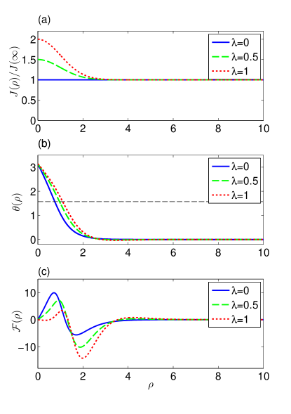
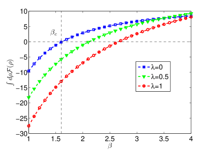
Below we show the -dependence of coupling , optimized trial function and energy density in different parameters (Fig. 1). We choose , , and for three pinning strength , and . We choose so that the size of the pinning center has the same order of magnitude as the radius of a skyrmion (so we can make patterned pinning centers as dense as possible, see Section. III.3). It is shown that for the uniform case , the energy density profile has a positive maximum and a negative minimum in the core region of a skyrmion. If we tune the magnetic field , there is a in which the positive “energy cost” and the negative “energy gain” cancel each other (Fig. 2). This is precisely the aforementioned phase boundary of skyrmion lattice phase and field polarized ferromagnetic phase.
If there is a local maximum of coupling , i.e., , the core energy is lowered. For the same , a larger makes the energy even lower (Fig. 2), thus there can be a negative energy skyrmion in the skyrmion gas phase (even in field polarized ferromagnetic phase). This pinned skyrmion becomes more stable than a “free skyrmion” from an energy point of view. This is what we call the pinning effect of a skyrmion by a local maximum of magnetic exchange strength. Besides lowering the energy, the local pinning center also makes the radius of a skyrmion a little larger.
III dynamical analysis
III.1 Landau-Lifshitz-Gilbert equation
To study the dynamics of the pinning process, we use discrete model of chiral magnets on a square lattice with the following Hamiltonian Han10 ; Han12 ; Li11 ; Mochizuki12 :
| (7) | |||||
where with are local magnetic moments at positions , for even number , and are two bond vectors in two dimensions. The dynamics of this magnetic system subjected to an applied electric current is obtained by Landau-Lifshitz-Gilbert (LLG) equation with a current term:
| (8) | |||||
where is the -component of the applied electric current and the phenomenological Gilbert damping parameter. The effective magnetic field is obtained by the Hamiltonian as:
| (9) | |||||
The current term in the LLG equation is the discrete version of the continuous term Han12 ; Zhang04 ; Zang11 ; Garst11 ; Garst12 . Here we take the cross product operation two times to the finite difference term to remove the parallel component with respect to , so that the local spin module conserves during the time evoluton.
We simulate the dynamical pinning and depinning processes as follows: we use an by square lattice with periodic boundary condition, the site-dependent exchange strength and DM interaction
| (10) |
are chosen to have a Gaussian profile, where is the discrete version of in Eq. 3 and is the wavelength of the chiral magnet on the lattice. Here we have shifted the position in the definition of to the center of the elemental plaquette in square lattice so that the periodic boundary condition is satisfied. We numerically integrate the LLG equation using fourth-order Runge–Kutta method and follow the position of the skyrmion. We choose time-step which is small enough for our study and we simulate the time evolution from up to .
III.2 The pinning process
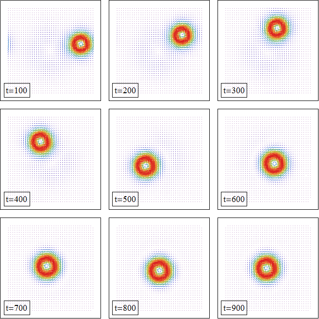
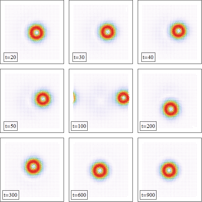
We first choose , , , , , , and with zero current. For the initial condition, we put a single skyrmion at position and which has an offset from the pinning center . The result of the time evolution is that the skyrmion undergoes a circular motion around the pinning center with the distance to the pinning center be smaller and smaller and finally stays at the pinning center (Fig. 3).
We have the following heuristic explanation of this process. Because the pinned skyrmion has lower energy than a free skyrmion and LLG equation has a damping term, the offset skyrmion has a tendency to move to the pinning center. If we treat a skyrmion as a point particle, the LLG dynamics of this single skyrmion has an effective kinetic term that gives transverse motion related to the pinning force Zang11 , that is, skyrmion motion is not parallel to the “attractive force” of the pinning center but makes an angle to the direction of the force. Combining the above two factors we get a circular motion with smaller and smaller distance to the pinning center.
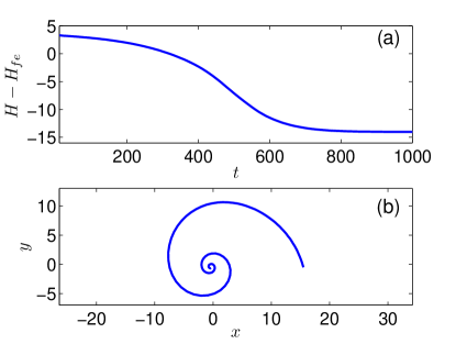
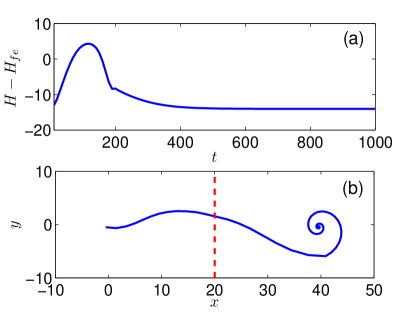
In Fig. 4 we show the evolution of the system energy (minus the energy of ferromagnetic state) versus time and the path of the skyrmion in the pinning process. We can see the system energy decreases with time, this is caused by the damping term in the LLG equation.
III.3 The depinning process
Now we study the depinning process of a pinned skyrmion. Because a pinned skyrmion has lower energy than a free one, to depin a skyrmion, we need to do positive work to it. In order to do work to a spin system, we can use a time-varying magnetic field or an applied adiabatic electric current. The magnetic field method is often used to sustain certain eigenmodes of the spin system near the ground state. According to Mochizuki Mochizuki12 , a time-varying in/out-of plane magnetic field with certain frequency can trigger the rotating/breathing internal mode of a single skyrmion. In this paper, we choose the electric current method to push the pinned skyrmion.
To simulate the depinning process, we apply a square-current-pulse of the form
to the pinned skyrmion configuration, where is the time when we stop the current and is the step-function.
We have adopted periodic boundary condition in our simulation of the LLG equation, so we are implicitly simulating an infinite pinning center lattice in which each pinning center lies at the origin point of our simulated by unit cell. We expect the following phenomenon for the depinning process. When the current is turned on, the pinned skyrmion is pushed by the current to move. The direction of the skyrmion motion is determined by: (1) the pinning force, (2) the pushing force (spin torque) of the current and (3) the tendency of the skyrmion to move not parallel to the forces. Let the direction of skyrmion motion to be in the -direction. At some time the skyrmion would leave the unit cell from the right boundary then enter the next unit cell from the left boundary and then move to the pinning center in this unit cell. Roughly at this time we turn off the current so the skyrmion is attracted by the pinning center in this unit cell and does circular motion just as the above pinning process and finally stays at the new pinning center.
To simulate this process, we use the parameters , and other parameters that are the same as the pinning simulation. We choose the current to be not parallel to the -direction so that the skyrmion moves approximately in the -direction. The numerical result is in agreement with our expectation (Fig. 5).
In Fig. 6(a) we show the evolution of system energy versus time. The system energy first increases and then decreases when the current is applied but always decreases when the current is turned off. This is because the current could do positive or negative work to the skyrmion depending on whether the current is pushing the skyrmion away from or toward a pinning center. But it is the positive work done by the current that depins the skyrmion. The system energy must decrease without the current due to the damping. The path of skyrmion motion in the whole process is shown in Fig. 6(b), where the red dashed line indicates the boundary of two successive unit cells of the simulated periodic lattice.
III.4 Critical current of the depinning process
We found in our simulation that the pinned skyrmion would not travel to other pinning centers but instead circulates around its own pinning position and finally stays at a nearby position if the applied current is not large enough. So there is a threshold critical current to depin a skyrmion.
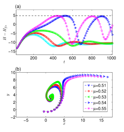
To study the critical current of depinning, we do a series of simulations with increasing current intensity with for a pinning strength . The result shows that there exists a critical current below which the skyrmion cannnot escape from the pinning center but circulates around the pinning center and the energy will not exceed the barrier energy set by the pinning center; but when the current is larger than the critical current, the skyrmion could escape from the pinning center and the energy exceeds the barrier energy (Fig. 7).
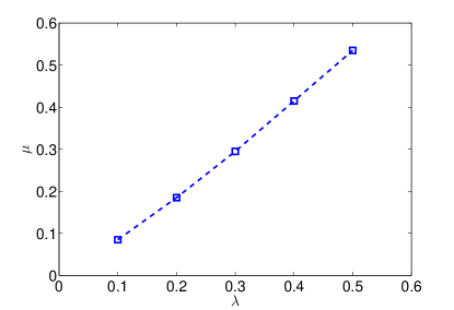
Next we simulate the critical current in different pinning stength and we find an almost linear dependence of the critical current with respect to the pinning strength (Fig. 8). The approximate relation is .
III.5 Estimation of the critical current
To estimate the critical current, we rescale the LLG in real material to our dimensionless form. Let the letters with a prime represent physical parameters in real material. First we do space rescaling, supposing the real material has magnetic exchange and crystal lattice spacing , then because the magnetic exchange scales as the inverse square of length, we have . Here is the rescaled magnetic exchange for our simulated space unit defined by , where is the helical wavelength in real material. Next we do time rescaling, in our simulation we have implicitly chosen the time unit to be . After these rescalings, the unit of the electric current is where is the spin quantum number of the local magnetic moment, is the fraction of spin polarization of the electric current. Next we substitute real parameters chosen as , , , and Han12 , then we get . With the above result we have (here refers to the pinning strength with order of magnitude in our simulation) and the typical pinning and depinning time around .
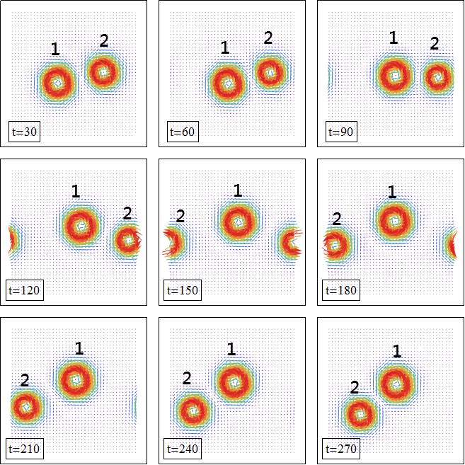
III.6 Multiple-skyrmion depinning
If there are more than one skyrmions around a pinning center, each skyrmion will feel simultaneously the attractive force of the pinning center and the repulsive force of other skyrmions because skyrmions repel each other. The net result is that the pinning effect is weakened. We simulate a two skyrmion case with , which is below the critical current for a single skyrmion. The result is that one of the skyrmions is depinned by this current (Fig. 9). Generalizing to more skyrmion case, we may say that multiple skyrmion configuration is more easily depinned. This is a well-known experimental result Pfleiderer12 .
III.7 Influence of the non-adiabatic spin-torque term
Besides the current term in our LLG equation, in conducting chiral magnets, there is another current related term which is the “non-adiabatic spin-torque term” Han12 ; Garst11 ; Garst12 . Combining this term to the existing current term we have:
| (11) |
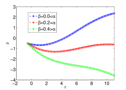
where represents the strength of the non-adiabatic torque. It is known that this term alters the trajectory of single skyrmions. When there is no pinning center, the skyrmion would move parallel to the applied current if the value equals to the Gilbert damping , otherwise the skyrmion motion would have a transverse component to the right/left of the current direction if is larger/smaller than Han12 .
When there is a pinning center, the -term has similar effect. In the following simulations we still use the current . In Fig. 10 we show that the trajectory of skyrmion in the depinning process is altered by the -term. Because there is a pinning center, even if the skyrmion still moves in a curved path.
IV summary and outlook
We proposed a mechanism to pin skyrmions by a local maximum of magnetic exchange strength in the conventional Heisenberg model with DM interaction. Physically, this local maximum of exchange strength is caused by a local maximum of the density of itinerate electrons in the material. We studied the effect of this local maximum by stationary analysis of the energy functional and found that this pinning center makes an isolated skyrmion more stable by lowering the core energy of it. Besides the stationary analysis, we also studied the dynamics of the chiral magnet with pinning center by LLG equation with a current term. We found that an offset skyrmion near the pinning center is attracted to the pinning center and undergoes a circular motion around the pinning center and finally stays at there. This pinned skyrmion can further be depinned by an applied current pulse, which pushes the skyrmion away from the pinning center and let the skyrmion be attracted by other pinning centers. Our simulation shows that there exists a critical current below which the pinned skyrmion cannot be depinned. We did a series of simulations and found that the critical current depends approximately linearly to the pinning strength and we estimated the critical current to have order of magnitude . With the pinning and depinning processes, we actually found a way to manipulate the skyrmions in artificially made pinning center lattice. This pinning center lattice is expected to be realized by putting metal grains on the surface of a chiral magnetic thin film in a certain way.
Our pinning and depinning mechanism resembles in spirit to the mechanism of the “magnetic
domain-wall racetrack memory” proposed by Parkin et. al. Parkin08
in which they use magnetic domain walls to represent information but here we use
single skyrmions. The main components of a racetrack memory are: (1) a writing unit,
(2) a racetrack and (3) a reading unit. For skyrmions, the writing unit could be
realized by the method of “skyrmion generation by a circular current” Han12 .
Our work can be thought of as a model of the two dimensional racetrack for single
skyrmions. In Parkin’s work they use patterned notches along the edges of the racetrack
to make pinning centers for the domain walls and they use electric current to depin
the domain walls to make the information “flow”. In our present proposal we
use patterned local maximums of exchange strength to pin skyrmions and still electric
current to depin them. The critical current to depin skyrmions from disorder is roughly
Pfleiderer12 , which is much smaller than our estimated
critical current to depin skyrmions from artificially made pinning center .
The above two values are both much smaller than the critical current in racetrack
memory which is of order . Skyrmions in conducting
chiral magnets can be more easily depinned and causes much smaller Joule-heating
for potential application.
Acknowledgements.
This work is supported by NSFC (Grant No. 11074216). The authors thank Prof. Jung Hoon Han for careful reading of the initial manuscript and fruitful suggestions.References
- (1) T. H. R. Skyrme, Nucl. Phys. 31, 556 (1962).
- (2) U. K. Rößler, A. N. Bogdanov, and C. Pfleiderer, Nature 442, 797 (2006).
- (3) C. Pappas, E. Lelièvre-Berna, P. Falus, P. M. Bentley, E. Moskvin, S. Grigoriev, P. Fouquet, and B. Farago, Phys. Rev. Lett. 102, 197202 (2009).
- (4) S. Mühlbauer, B. Binz, F. Jonietz, C. Pfleiderer, A. Rosch, A. Neubauer, R. Georgii, and P. Böni, Science 323, 915 (2009).
- (5) X. Z. Yu, Y. Onose, N. Kanazawa, J. H. Park, J. H. Han, Y. Matsui, N. Nagaosa, and Y. Tokura, Nature 465, 901 (2010).
- (6) X. Z. Yu, N. Kanazawa, Y. Onose, K. Kimoto, W. Z. Zhang, S. Ishiwata, Y. Matsui, and Y. Tokura, Nat. Mater. 10, 106 (2011).
- (7) S. Heinze, K. von Bergmann, M. Menzel, J. Brede, A. Kubetzka, R. Wiesendanger, G. Bihlmayer, and S. Blügel, Nat. Phys. 7, 713 (2011).
- (8) S. Seki, X. Z. Yu, S. Ishiwata, and Y. Tokura, Science 336, 198 (2012).
- (9) I. Dzyaloshinsky, J. Phys. Chem. Solids 4, 241 (1958).
- (10) T. Moriya, Phys. Rev. 120, 91 (1960); Phys. Rev. Lett. 4, 228 (1960).
- (11) L. Shekhtman, O. Entin-Wohlman, and A. Aharony, Phys. Rev. Lett. 69, 836 (1992).
- (12) J. H. Han, J. Zang, Z. Yang, J.-H. Park, and N. Nagaosa, Phys. Rev. B 82, 094429 (2010).
- (13) Y.-Q. Li, Y.-H. Liu and Y. Zhou, Phys. Rev. B. 84, 205123 (2011).
- (14) M. Mochizuki, Phys. Rev. Lett. 108, 017601 (2012).
- (15) O. Petrova and O. Tchernyshyov, Phys. Rev. B 84, 214433 (2011).
- (16) T. Schulz, R. Ritz, A. Bauer, M. Halder, M. Wagner, C. Franz, C. Pfleiderer, K. Everschor, M. Garst and A. Rosch, Nat. Phys. 8, 301 (2012).
- (17) M. Lee, W. Kang, Y. Onose, Y. Tokura, and N. P. Ong, Phys. Rev. Lett. 102, 186601 (2009).
- (18) A. Neubauer, C. Pfleiderer, B. Binz, A. Rosch, R. Ritz, P. G. Niklowitz, and P. Böni, Phys. Rev. Lett. 102, 186602 (2009).
- (19) S. Zhang and Z. Li, Phys. Rev. Lett. 93, 127204 (2004).
- (20) G. Tatara and H. Kohno, Phys. Rev. Lett. 92, 086601 (2004).
- (21) S. E. Barnes and S. Maekawa, Phys. Rev. Lett. 95, 107204 (2005).
- (22) S. Zhang and S. S.-L. Zhang, Phys. Rev. Lett. 102, 086601 (2009).
- (23) F. Jonietz, S. Mühlbauer, C. Pfleiderer, A. Neubauer, W. Münzer, A. Bauer, T. Adams, R. Georgii, P. Böni, R. A. Duine, K. Everschor, M. Garst, and A. Rosch, Science 330, 1648 (2010).
- (24) K. Everschor, M. Garst, R. A. Duine, and A. Rosch, Phys. Rev. B 84, 064401 (2011).
- (25) K. Everschor, M. Garst, B. Binz, F. Jonietz, S. Mühlbauer, C. Pfleiderer, and A. Rosch, arXiv:1204.5051v1 (2012).
- (26) J. Zang, M. Mostovoy, J. H. Han, and N. Nagaosa, Phys. Rev. Lett. 107, 136804 (2011).
- (27) Y. Tchoe and J. H. Han, Phys. Rev. B 85, 174416 (2012).
- (28) S. S. P. Parkin, M. Hayashi, and L. Thomas, Science 320, 190 (2008).