Plasmonic Nanoantennas for Efficient Control of Polarization-Entangled Photon Pairs
Abstract
\cbstartWe suggest a novel source of polarization-entangled photon pairs based on a cross-shaped plasmonic nanoantenna driven by a single quantum dot. The integration of the nanoantenna with a metal mirror overcomes the fundamental tradeoff between the spontaneous emission (SE) enhancement and the extraction efficiency typical of microcavity and nanowire-based architectures. With a very-high extraction efficiency of entangled photons () at m and large SE enhancement () over a broad nm spectral range, the proposed design will pave the way toward reliable integrated sources of nonclassical light.\cbend
pacs:
03.67.Bg, 78.67.Hc, 71.35.-y, 73.20.MfQuantum communication systems and computers can achieve unparalleled levels of security and productivity by encoding information using polarization-entangled photon pairs Bouwmeester et al. (2000). Photonic chips capable of both generating polarization-entangled photon pairs and performing logic quantum operations Hausmann et al. (2012); *sol12; *hor12; *sha12 are a promising technique \cbstartfor developing practical\cbend quantum communication and computers. \cbstartIt would be\cbend impossible without compact, integrable and scalable sources of polarization-entangled photon pairs combining broad bandwidth, large efficiency and high fidelity Bouwmeester et al. (2000); Henini (2008).
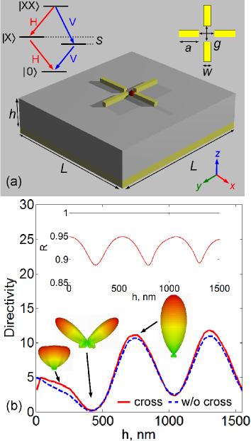
Single semiconductor quantum dots (QDs) can be used as a triggered source of polarization-entangled photon pairs [Forareviewsee; e.g.; ][; andreferencesthereinforadiscussionofexperimentaldemonstrationofentangledphotonpairswithsingleQDs.]shi07. As shown in the inset in Fig. (a), the radiative decay of the biexciton state (XX) in a QD emits a pair of photons, with the polarization determined by the spin of the intermediate exciton state (X). In an ideal QD with degenerate X states (the energy splitting Shields (2007)), the polarization of the XX photon is predicted to be entangled with that of X photon, forming the state , where H and V denote the polarization of the XX and X photons.
In practice, \cbstarta strong scattering of emitted entangled photons over a broad angular spectrum and the resulting far-field divergence severely limit the extraction efficiency. Moreover,\cbend the degree of entanglement is still limited by QD dephasing and residual excitonic fine-structure splitting Henini (2008). The use of cavity effect Shields (2007); Larqué et al. (2009); Dousse et al. (2010) improves this situation dramatically: the emission is directed into a single mode and the emission lifetime is reduced due to the SE enhancement effect, which makes the source more deterministic and reliable. Conversely, one can avoid cavity effect and utilize photonic crystal waveguides Lecamp et al. (2007); *man07; *lun08 or semiconductor nanowires Claudon et al. (2010); *bab10; *rei12. While these architectures may offer high multiphoton probability suppression Lund-Hansen et al. (2008) and very high extraction efficiency through a microscope objective Claudon et al. (2010); *bab10; *rei12, they provide a low SE enhancement insufficient for the restoration of polarization entanglement Henini (2008); Larqué et al. (2008). Large SE rates can be achieved using various metallic nanostructures Anger et al. (2006); *kin09; *sch09; *sor11; *cho11_1; *rus12, including metal-coated semiconductor nanowires \cbstartChoy et al. (2011); *gan12; Maksymov et al. (2010)\cbend. However, the extraction efficiency of entangled photons in such structures is compromised by impedance mismatch between the confined nanowire modes and freely propagating light Maksymov et al. (2010).
Recent advances in nanofabrication have demonstrated that optical nanoantennas Novotny and van Hulst (2011), such as, e.g., plasmonic Yagi-Uda\cbstart-type architectures driven by a single emitter Koenderink (2009); *cur10; *est10; *mak11\cbend, may have much larger SE enhancement as compared with nanocavities and nanowires. Moreover, in general, a nanoantenna is an intrinsically good transformer of localized energy to freely propagating light Novotny and van Hulst (2011), which favours high extraction efficiency of the emitted photons into a cone with a narrow opening angle given by the numerical aperture of the detection optics Lee et al. (2011); *che11. However, the use of many nanoantenna architectures for the emission of polarization-entangled photon pairs is challenging because they provide an increased SE enhancement for one photon polarization Carminati et al. (2006), which leads to the generation of nonmaximally entangled states Henini (2008).
In this Letter, we suggest a novel QD-based source of polarization-entangled photon pairs benefiting from a broadband SE rate enhancement and, to our best knowledge, very-high extraction efficiency of photon pairs. This is achieved with a cross-shaped plasmonic nanoantenna inspired by radio-frequency cross antennas Balanis (2005) recently adopted in optics (see, e.g., Biagioni et al. (2009)). In contrast to Ref. Biagioni et al. (2009), our cross structure is integrated with a metal mirror similar to that demonstrated in the literature Friedler et al. (2009); *ahm11. The mirror plays a crucial role in the performance of the device since it forms a sharp far-field emission pattern and facilitates increased extraction efficiency. We also demonstrate that a pure entangled photon emission with a high fidelity is \cbstartstill possible for the misaligned QDs from the centre\cbend of the cross. The proposed design is consequently a major contributor to the development of efficient sources of nonclassical light for photonic quantum technologies.
The design and interpretation were performed using CST Microwave Studio implementing a finite integration technique, which was tested on analytically solvable models Carminati et al. (2006). Except when otherwise specified, the emitter is modelled as an in-plane electric dipole polarized horizontally [along the x-axis in Fig. (a)] and located at the center of the cross. Since the cross displays symmetry, the results obtained with the horizontal dipole can be generalized for the case of the vertically polarized dipole [along the y-axis in Fig. (a)] representing photons of V-polarization.
The cross consists of four identical gold nanorods with a common feed gap [Fig. (a), main panel]. It sits on a pedestal glass substrate of height and a side size with an underlying gold mirror. The mirror resides on the top of an infinitely wide glass bulk. For the optimal performance around nm the length of the nanorods is chosen to be nm and their width and height are nm. The central gap between the nanorods is nm in both the x- and y-directions. The frequency-dependent refractive index of gold is taken from Ref. Palik (1985); that of glass is chosen as .
The choice of the area of the pedestal substrate is of crucial importance for achieving a directive far-field pattern of the nanoantenna. It is known that the maximum directivity obtainable from an antenna is proportional to the physical aperture Kraus (1988). For the cross nanoantenna in Fig. (a) is determined by the area of the pedestal substrate. In auxiliary simulations we observe that the excitation of the nanoantenna sitting on a large area substrate () results in launching surface plasmons propagating along the mirror surface. It enables plasmons contributing to the emission pattern as highly undesirable side lobes. The formation of side lobes is suppressed by using a pedestal substrate with a mirror of a smaller size nm.
In order to gain more insight into the directivity of the nanoantenna, in Fig. (b) we compare of the structures with and without the cross and observe that depends on the distance between the emitter and the mirror. The cross plays a little role in the formation of the emission pattern. By investigating the reflectivity of the infinitely wide glass layer on the top of the gold bulk as a function of [inset in Fig. (b)] we reveal that a directive emission pattern is formed solely by the mirror under condition that the reflection from the covering glass is minimum. This condition fulfils at, e.g., nm corresponding to the second minimum of and, therefore, in what follows we consider this value only. The first minimum of occurs when the emitter is close to the mirror, which incurs increased absorption losses and undesired broad emission pattern.
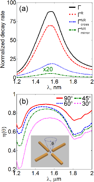
By definition, the directivity does not manifest the enhancement of the SE rate provided by the nanoantenna. We therefore consider the normalized spontaneous decay rate that, in the weak coupling regime, is related to the rate of energy dissipation experienced by a classical electric dipole: , where is the power emitted by the dipole in the presence of the nanoantenna and is the power of the same dipole in free space Carminati et al. (2006). We calculate the normalized radiative decay rate , being the far-field radiated power. As an increase in is typically concomitant with an unwanted and usually strong increase in the nonradiative decay rate , we also calculate , where is the power absorbed inside the cross and the mirror. Owing to energy conservation the total decay rate is .
Fig. shows the spectral characteristics of the nanoantenna. The peak value of in Fig. (a) is at the wavelength of nm, which is times larger than that of a recently reported metal-coated nanowire sources of entangled photon pairs Maksymov et al. (2010). The peak value of reaches giving rise to a radiation efficiency of at nm. Furthermore, the cross nanoantenna is broadband in frequency having a remarkable nm bandwidth at the full-width at half-maximum of , which is times larger than the bandwidth of semiconductor and metal-coated nanowire-based sources of single photons Claudon et al. (2010); *bab10; *rei12; Maksymov et al. (2010). The extraction efficiency in Fig. (b), defined as a fraction of emitted photons that are collected above the top of the cross for the opening angle [inset in Fig. (b)], is greater than for an opening angle as small as in a broad nm range. In overall, observed is comparable with that of state-of-the-art photonic nanowire single-photon sources known to boast very high extraction efficiency Claudon et al. (2010); *bab10; *rei12. It is very close to that of recently demonstrated planar dielectric nanoantennas for single-photon emission Lee et al. (2011); *che11, which, however, do not provide any SE enhancement.
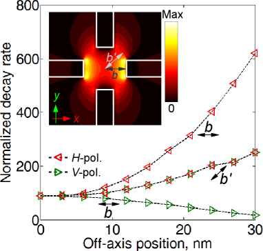
Thus far we have assumed that the nanoantenna is excited with a QD precisely placed at the center. In this case the SE enhancement and far-field emission pattern underwent by the H- and V-dipole are identical due to the mode degeneracy. In practice, however, the QD will be not exactly centered. Fig. shows of the H- and V-polarized dipoles as a function of the axial () and diagonal () displacement from the central position (inset in Fig. ). of the H-dipole increases rapidly as the dipole approaches one of the cross arms. Since the total power emitted by the dipole is proportional to the electric field E at the dipole’s origin Stratton (1941), the increase in is due to an increase in in the direction of the cross arm (inset in Fig. ). A rapid decrease in for the V-dipole is due to a rapid decrease in . This lift of degeneracy results in an increased SE enhancement for one recombination path and inevitably leads to the generation of nonmaximally entangled states Henini (2008). As for the H- and V-dipoles displaced along the diagonal, we find that their changes simultaneously because of the same variations of and along the diagonal direction.
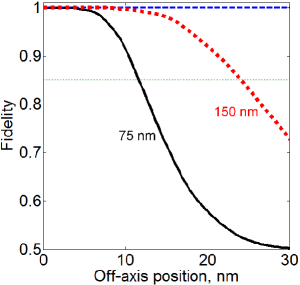
The asymmetry of influences the degree of entanglement, which can be quantified by the fidelity of entangled photons pairs Larqué et al. (2009); Dousse et al. (2010). measures the similarity of the emitted state to the maximally entangled Bell state . Under the assumption that the anisotropic spin exchange energy of the QD is negligible, we estimate the density matrix of the photon pairs in the polarization basis as\cbend Larqué et al. (2009); [A.Beveratos(personalcommunication).Eq.(C.4)inRef.~\cite[citep]{\@@bibref{AuthorsPhrase1Year}{lar09}{\@@citephrase{; }}{}}containsmisprints.Weusethecorrectequation][]dummy
| (5) |
being the relative difference of for the H- and V-dipoles\cbend. In Fig. we plot calculated as \cbstartTr(\cbend, where Tr(.) is the trace and is the density matrix of the entangled photons emitted by a QD displaced from the central position. We observe required to violate the original Bell inequality Bouwmeester et al. (2000) for axial displacements of up to nm. For the diagonal displacement \cbstart\cbend because (see Fig. ).
Precise positioning of a single QD within the gap of the cross structure is challenging but possible thanks to the recent advances in nanofabrication technologies. For example, strong coupling of a single QD with a cavity architecture was achieved in Ref. Thon et al. (2009) using an all-optical scheme ensuring a sub-10 nm accuracy. Topdown fabrication techniques were used in Ref. Dregely et al. (2012) to achieve positioning of individual quantum emitters relative to plasmonic nanoantennas with an accuracy better than 10 nm. More importantly, the combination of the cross nanoantenna with the gold mirror allows relaxing the requirement for precise positioning of the QD by increasing the gap of the cross. It is possible because is practically independent of the presence of the cross structure [see Fig. (b)]. Simulations for the cross gap of nm reveal (Fig. ) that for axial displacements of nm implying that more mature QD alignment procedures with an accuracy of better than 30 nm can be used Pfeiffer et al. (2012). Eventually, decreases as increases the gap. For nm we obtain and at nm [Supplementary Material] with the same extraction efficiency as for nm. We note that suffices for the emission of entangled photons Larqué et al. (2008).
In conclusion, we have demonstrated \cbstarta novel source of polarization-entangled photon pairs based on a plasmonic nanoantenna driven by a single QD. The source combines\cbend large broadband SE enhancement and very-high extraction efficiency, \cbstartwhich is not achievable with competing devices offering either high SE enhancement or high efficiency\cbend. It extends the applicability of plasmonic nanoantennas to sources of nonclassical light and anticipates their integration with photonic circuits for application in quantum communication and computing.
This work was supported by the Australian Research Council. The authors confirm invaluable discussions with I. Staude, P. Belov, and F. Demming (CST).
References
- Bouwmeester et al. (2000) D. Bouwmeester, A. K. Ekert, and A. Zeilinger, The Physics of Quantum Information (Springer-Verlag, Berlin, 2000).
- Hausmann et al. (2012) B. J. M. Hausmann, B. Shields, Q. Quan, P. Maletinsky, M. McCutcheon, J. T. Choy, T. M. Babinec, A. Kubanek, A. Yacoby, M. D. Lukin, and M. Lonc̆ar, Nano Lett. 12, 1578 (2012).
- Solntsev et al. (2012) A. S. Solntsev, A. A. Sukhorukov, D. N. Neshev, and Y. S. Kivshar, Phys. Rev. Lett. 108, 023601 (2012).
- Horn et al. (2012) R. Horn, P. Abolghasem, B. J. Bijlani, D. Kang, A. S. Helmy, and G. Weihs, Phys. Rev. Lett. 108, 153605 (2012).
- Shadbolt et al. (2012) P. J. Shadbolt, M. R. Verde, A. Peruzzo, A. Politi, A. Laing, M. Lobino, J. C. F. Matthews, M. G. Thompson, and J. L. O’Brien, Nat. Photon. 6, 45 (2012).
- Henini (2008) M. Henini, Handbook of Self Assembled Semiconductor Nanostructures for Novel Devices in Photonics and Electronics (Elsevier Science, Amsterdam, 2008).
- Shields (2007) A. J. Shields, Nat. Photon. 1, 215 (2007).
- Larqué et al. (2009) M. Larqué, T. Karle, I. Robert-Philip, and A. Beveratos, N. J. Phys. 11, 033022 (2009).
- Dousse et al. (2010) A. Dousse, J. Suffczyński, A. Beveratos, O. Krebs, A. Lemaître, I. Sagnes, J. Bloch, P. Voisin, and P. Senellart, Nature (London) 466, 217 (2010).
- Lecamp et al. (2007) G. Lecamp, P. Lalanne, and J. P. Hugonin, Phys. Rev. Lett. 99, 023902 (2007).
- Manga Rao and Hughes (2007) V. S. C. Manga Rao and S. Hughes, Phys. Rev. B 75, 205437 (2007).
- Lund-Hansen et al. (2008) T. Lund-Hansen, S. Stobbe, B. Julsgaard, H. Thyrrestrup, T. Sünner, M. Kamp, A. Forchel, and P. Lodahl, Phys. Rev. Lett. 101, 113903 (2008).
- Claudon et al. (2010) J. Claudon, J. Bleuse, N. S. Malik, M. Bazin, P. Jaffrennou, N. Gregersen, C. Sauvan, P. Lalanne, and J.-M. Gérard, Nat. Photon. 4, 174 (2010).
- Babinec et al. (2010) T. M. Babinec, B. M. Hausmann, M. Khan, Y. Zhang, J. Maze, P. R. Hemmer, and M. Lonc̆ar, Nat. Nanotech. 5, 195 (2010).
- Reimer et al. (2012) M. E. Reimer, G. Bulgarini, N. Akopian, M. Hocevar, M. B. Bavinck, M. A. Verheijen, E. P. A. M. Bakkers, L. P. Kouwenhoven, and V. Zwiller, Nat. Commun. 3, 737 (2012).
- Larqué et al. (2008) M. Larqué, I. Robert-Philip, and A. Beveratos, Phys. Rev. A 77, 042118 (2008).
- Anger et al. (2006) P. Anger, P. Bharadwaj, and L. Novotny, Phys. Rev. Lett. 96, 113002 (2006).
- Kinkhabwala et al. (2009) A. Kinkhabwala, Z. Yu, S. Fan, Y. Avlasevich, K. Müllen, and W. E. Moerner, Nat. Photon. 3, 654 (2009).
- Schietinger et al. (2009) S. Schietinger, M. Barth, T. Aichele, and O. Benson, Nano Lett. 9, 1694 (2009).
- Sorger et al. (2011) V. J. Sorger, N. Pholchai, E. Cubukcu, R. F. Oulton, P. Kolchin, C. Borschel, M. Gnauck, C. Ronning, and X. Zhang, Nano Lett. 11, 4907 (2011).
- Cho et al. (2011) C.-H. Cho, C. O. Aspetti, M. E. Turk, J. M. Kikkawa, S.-W. Nam, and R. Agarwal, Nat. Mater. 10, 669 (2011).
- Russell et al. (2012) K. J. Russell, T.-L. Liu, S. Cui, and E. L. Hu, Nat. Photon. doi: 10.1038/NPHOTON.2012.112 (2012).
- Choy et al. (2011) J. T. Choy, B. J. M. Hausmann, T. M. Babinec, I. Bulu, M. Khan, P. Maletinsky, A. Yacoby, and M. Lonc̆ar, Nat. Photon. 5, 738 (2011).
- Gan et al. (2012) C. H. Gan, J. P. Hugonin, and P. Lalanne, Phys. Rev. X 2, 021008 (2012).
- Maksymov et al. (2010) I. S. Maksymov, M. Besbes, J. P. Hugonin, J. Yang, A. Beveratos, I. Sagnes, I. Robert-Philip, and P. Lalanne, Phys. Rev. Lett. 105, 180502 (2010).
- Novotny and van Hulst (2011) L. Novotny and N. van Hulst, Nat. Photon. 5, 83 (2011).
- Koenderink (2009) A. F. Koenderink, Nano. Lett. 9, 4228 (2009).
- Curto et al. (2010) A. G. Curto, G. Volpe, T. H. Taminiau, M. P. Kreuzer, R. Quidant, and N. F. van Hulst, Science 329, 930 (2010).
- Esteban et al. (2010) R. Esteban, T. V. Teperik, and J. J. Greffet, Phys. Phys. Lett. 104, 026802 (2010).
- Maksymov et al. (2011) I. S. Maksymov, A. R. Davoyan, and Y. S. Kivshar, Appl. Phys. Lett. 99, 083304 (2011).
- Lee et al. (2011) K. G. Lee, X. W. Chen, H. Eghlidi, P. Kukura, R. Lettow, A. Renn, V. Sandoghdar, and S. Götzinger, Nat. Photon. 5, 166 (2011).
- Chen et al. (2011) X. W. Chen, S. Götzinger, and V. Sandoghdar, Opt. Lett. 36, 3545 (2011).
- Carminati et al. (2006) R. Carminati, J.-J. Greffet, C. Henkel, and J. M. Vigoureux, Opt. Commun. 261, 368 (2006).
- Balanis (2005) C. A. Balanis, Antenna Theory: Analysis and Design (Wiley, New Jersey, 2005).
- Biagioni et al. (2009) P. Biagioni, J. S. Huang, L. Duò, M. Finazzi, and B. Hecht, Phys. Rev. Lett. 102, 256801 (2009).
- Friedler et al. (2009) I. Friedler, C. Sauvan, J. P. Hugonin, P. Lalanne, J. Claudon, and J.-M. Gérard, Opt. Express 17, 2095 (2009).
- Ahmed and Gordon (2011) A. Ahmed and R. Gordon, Nano Lett. 11 (2011).
- Palik (1985) E. D. Palik, Handbook of Optical Constants of Solids (Academic Press, San Diego, 1985).
- Kraus (1988) J. D. Kraus, Antennas (McGraw-Hill, London, 1988).
- Stratton (1941) J. A. Stratton, Electromagnetic Theory (McGraw-Hill, New York, 1941).
- (41) .
- Thon et al. (2009) S. M. Thon, M. T. Rakher, H. Kim, J. Gudat, W. T. M. Irvine, P. M. Petroff, and D. Bouwmeester, Appl. Phys. Lett. 94, 111115 (2009).
- Dregely et al. (2012) D. Dregely, K. Lindfors, J. Dorfmüller, M. Hentschel, M. Becker, J. Wrachtrup, M. Lippitz, R. Vogelgesang, and H. Giessen, Phys. Status Solidi B 249, 666 (2012).
- Pfeiffer et al. (2012) M. Pfeiffer, K. Lindfors, P. Atkinson, A. Rastelli, O. G. Schmidt, H. Giessen, and M. Lippitz, Phys. Status Solidi B 249, 678 (2012).