Spin-polarized tunneling current through a thin film of a topological insulator in a parallel magnetic field
Abstract
We calculate the tunneling conductance between the surface states on the opposite sides of an ultra-thin film of a topological insulator in a parallel magnetic field. The parallel magnetic field produces a relative shift of the in-plane momenta of the two surfaces states. An overlap between the shifted Fermi circles and spinor wave functions result in unusual dependence of the tunneling conductance on the magnetic field. Because spin orientation of the electronic surface states in topological insulators is locked to momentum, spin polarization of the tunneling current can be controlled by the magnetic field.
pacs:
03.65.Vf, 73.50.JtI Introduction.
In the past few years, there has been a rapid progress in the field of topological insulators (TIs) TI-Review . The three-dimensional (3D) topological insulators have the helically-spin-polarized surface states with the two-dimensional (2D) Dirac dispersion, which are observed experimentally TI-Experiments . TIs not only offer an exciting playground for fundamental physics, but also have a variety of potential applications ranging from spintronics Garate-2010 ; Yokoyama-2010 ; Yokoyama-2010a ; Burkov-2010 ; Mondal-2010 ; Zhai-2011 ; Wu-2011 ; Appelbaum-2011 ; Suwanvarangkoon-2011 ; JZhang-2012 to quantum computing QuantumComputing . However, the experiments show that the Fermi level is often lifted to the conduction band, thus making the topological surface states less relevant for the properties of real materials BadInsulators . In part, this motivated the study of the thin films of TIs, where the Fermi level, bulk gap and the hybridization between the opposite surface states can be tuned ThinFilmsTuning ; FieldEffectTransistor ; Molenkamp . A number of intriguing effects for the TI films were predicted in the case where the top and bottom surfaces interact TI-effects . In the ultra-thin limit, a gap opens in the surface states electronic spectrum due to hybridization between the opposite surfaces FieldEffectTransistor ; ThinFilmModels ; YZhang-2010 ; Taskin-2012 .
While most papers study the in-plane transport properties of the surface states, here we study the tunneling conductance per unit area across the ultra-thin TI film in the presence of a parallel magnetic field (see Fig. 1). The in-plane magnetic field results in a relative shift of the Dirac cones of the surface states in momentum space, as discussed in related works on graphene bilayer Parallel1 ; Parallel2 . However, unlike the spectrum of graphene, the spectrum of the TI thin film remains gapped until a critical value of the magnetic field is achieved Zyuzin-2011 . Motivated by the original measurements of vs for a GaAs bilayer by Eisenstein et al. Eisenstein-1991 , here we calculate the tunneling conductance for a TI film as a function of the parallel magnetic field. In contrast to other systems, the spin structure of the electronic spectrum for the surface states of TI results in unusual dependence of the tunneling conductance on . In a recent experiment Parallel-experiment , the authors observed a strong dependence of the out-of-plane current in a film of Bi2Te3. The predicted theoretical dependence vs is in qualitative agreement with the experimental curve. In addition, we predict that the spin polarization of the tunneling current is proportional to the magnetic field. The spin polarization can be achieved for an experimentally accessible strength of the magnetic field.
II The Model.
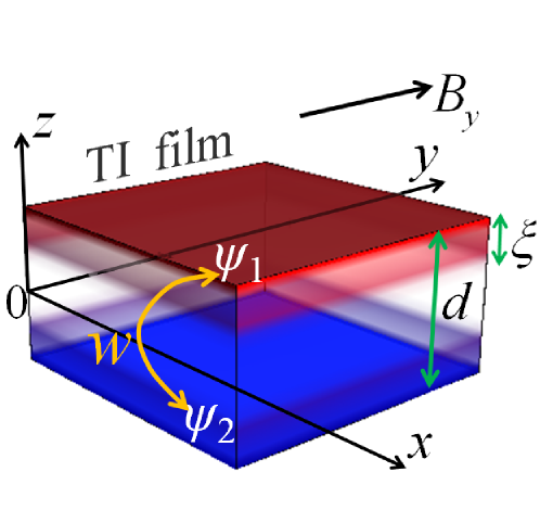
Let us consider a film of TI, which has two states and localized at the opposite surfaces of the film, as shown in red and blue in Fig. 1. While the wave functions are localized in the direction, electrons are free to move parallel to the surface, so the in-plane momentum is a good quantum number. For clarity of consideration, we model the surface states by the simple Rashba Hamiltonians
| (1) | |||
| (2) |
Different signs correspond to the surface states and and describe the unit Rashba vectors , which are collinear with the normals to the corresponding surfaces. The variable has dimensions of velocity, and denotes a full set of the operators acting in the spin space, where is a unit matrix and are the Pauli matrices. Hamiltonian (2) has the following eigenstates and eigenenergies
| (3) |
where the spectrum has a well-known form of the 2D Dirac cone. The spinors in Eq. (3) describe the helical spin-momentum locking with the spin polarization perpendicular to the momentum
| (4) |
so the helicity (4) is opposite for the and bands. Because of the minus sign for in Eq. (1), the bands are energetically-inverted, and, so, the helicities for the opposite surface states and are opposite for a fixed energy. The wave functions of the surface states and decay into the bulk and have a finite decay length , as illustrated in Fig. 1. So, when the thickness of the film becomes comparable with the decay length , there is a finite coupling between the surface states , which we assume to be proportional to the unit matrix in the spin space. So, the TI film can be modeled by a Hamiltonian , which acts on the 4-component wave function
| (9) |
This Hamiltonian was also used in Ref. Zyuzin-2011 for description of a thin film. Even though the bulk bands usually contribute to the electronic properties of the real materials BadInsulators , we ignore a possible bulk effect in order to highlight the contribution of the surface states. Hamiltonian (9) has the spectrum , where the energy gap is determined by the tunneling element . Experimentally, gap varies from eV for the ultra-thin nm film to eV for the nm film of Bi2Se3 YZhang-2010 .
III Spectrum in a parallel field.
Let us now discuss the spectrum of the TI thin film in a parallel magnetic field . In the Landau gauge , the Peierls substitution transforms the Hamiltonian (9) into
| (10) |
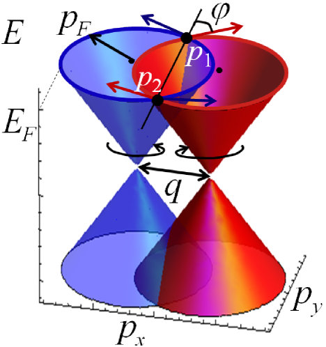
The Zeeman term can be included in the definition of Zyuzin-2011 ; Zeeman . Notice that the parallel magnetic field leads to the opposite momentum shifts on the opposite surfaces located at . Indeed, consider an electron traveling between the surfaces with the classical velocity in the direction. Then, the Lorentz force results in the in-plane momentum change between the opposite surfaces. So, in the limit , the spectrum of the Hamiltonian (10) is given by the two shifted Dirac cones
| (11) |
as shown in Fig. 2. A similar shift of the Dirac cones was discussed for graphene multilayer due to a parallel magnetic field Parallel1 ; Parallel2 and for a twisted graphene bilayer Andrei-2010 . In general, when is not small, the spectrum of Hamiltonian (10) was calculated in Ref. Zyuzin-2011 . However, we focus on the former case when is small and include as a perturbation.
IV Tunneling current in a parallel field.
 |
When a small potential difference is applied between the opposite surfaces of the film, the out-of-plane tunneling current per unit area
| (12) |
flows between the opposite surfaces, where and are the annihilation operators on the corresponding surface states. Here, we put for simplicity and reestablish the correct units in the end of calculation. So, the tunneling current is written in a convenient four-component form, such that and are the charge and spin currents. Using the linear-response theory for as a perturbation TunnelingConductance , the tunneling conductances per unit area can be expressed through the spectral functions evaluated at the Fermi energy as
| (13) |
Here, has four components, where and correspond to the tunneling conductance for charge and spin currents. The spectral functions are given in the momentum space
where the opposite signs correspond to the opposite surfaces and , and the spinors are defined in Eq. (3). Using Eqs. (13) and (IV), let us first calculate the tunneling conductance for the charge current
| (15) |
where is the Fermi momentum. According to Eq. (15), the tunneling current is carried by the electrons that have the in-plane momenta and corresponding to the intersection points of the shifted Fermi circles , as shown by the thick dots in Fig. 2. In addition, there is a contribution due to the non-trivial scalar product between the spinors (3) corresponding to the Fermi circles.
As a warm up, let us first consider the case where is no spin-momentum locking, so and Eq. (15) gives
| (16) |
The tunneling conductance diverges at and , as shown by the dashed line in Fig. 3(a). For a small magnetic field , the tunneling conductance is large because of the large overlap between the two Fermi circles shown in the left part of Fig. 3(b). For an intermediate magnetic field , the Fermi circles intersect only at two points and , so the tunneling conductance decreases. For , the two points and come together, so the Fermi circles overlap at the locally flat regions as shown in the right part of Fig. 2(b), and the tunneling conductance is large again. Once , the two Fermi circles separate, and the tunneling conductance drops to zero. The experimental curve of the tunneling conductance for a GaAs bilayer Eisenstein-1991 shows behavior similar to Eq. (16), but the divergences at and are smeared out due to a finite scattering time .
Now, let us consider the form-factor in Eq. (15) arising from the spinor eigenstates (3) of the Rashba Hamiltonian (2). As discussed above, the surface states have opposite spin polarizations. In Figs. 2 and 3, the polarizations corresponding to the different Fermi circles are shown by the blue and red arrows intersecting at the angle , the value of which follows from simple trigonometry: . The form-factor in Eq. (15) takes into account an overlap between the spinors on the different Fermi circles and is equal to . So, the tunneling conductance (15) is multiplied by a factor of relative to Eq. (16)
| (17) |
The tunneling conductance given by Eq. (17) is plotted by the solid line in Fig. 3(a). In contrast to , the tunneling conductance is suppressed as , because spin polarizations of the Fermi circles are opposite at the points and , as shown in Fig 3(b) on the left. This is a signature of the opposite spin helicity of the Fermi circles and thus may be used as a way to detect it. For near , however, the spin configurations are almost aligned, as shown in Fig. 3(b), so, and become equal.
The non-trivial spin structure of the Fermi circles not only modifies the tunneling current, but also makes it spin-polarized. Let us define spin polarization as the ratio of the spin current over the charge current
| (18) |
where the second equation follows from the definition of the conductance. Using the property that the eigenstates (3) have the well-defined spin orientation (4), we obtain from Eq. (13)
| (19) |
So, the spin polarization of the tunneling current is determined by the vector sum of the spin directions at the momenta and . Indeed, in the process of tunneling, the electrons with the in-plane momenta and move from the “blue” to “red” Fermi circle, carrying the total spin, which is a vector sum of the spins at the momenta and , in agreement with Eq. (19). The helical spin configuration (4) is such that the net spin polarization is parallel and proportional to , as illustrated in Fig. 3(b). At , the spins at the points and are opposite, and the spin polarization of the tunneling current vanishes. At , the spins at the points and are collinear and the tunneling current is fully spin-polarized. Also, notice that the electron tunneling at changes the spin polarization from the “blue” to “red” arrow, thus creating a torque in direction. However, the torque is opposite at , so the net torque is zero.
V Experimental relevance.
Let us estimate the critical magnetic field where the Fermi circles almost detach, i.e., where . We take the realistic value m/s, assume nm (5 quintuple layers of Bi2Se3) and carrier concentration corresponding to meV. Using Eq. (10) for , we estimate the critical value of the field as T. This value is experimentally accessible and can be further reduced by either increasing the thickness or decreasing the Fermi momentum .
An intriguing strong negative magnetoresistance effect was reported for the Sn-doped films of Bi2Te3 in Ref. Parallel-experiment . A weak in-plane magnetic field less than 1 T causes a large drop of the out-of-plane resistance as shown in Fig. 4(c) of Ref. Parallel-experiment . Since , a decrease in resistance corresponds to an increase in conductance , which qualitatively agrees with plot of vs shown in Fig. 3(a) of our paper. In addition, the effect of Sn doping was studied in Ref. Parallel-experiment . The Sn doping leads to a decrease of carrier concentration and , which is corroborated by an increase of resistance in the experiment. At the same time, the magnitude of negative magnetoresistance increases dramatically with doping, as shown in Fig. 4(a,b) of Ref. Parallel-experiment . This observation is consistent with Eq. (17), where the conductance increases when decreases (for ). However, our idealized model may be not fully applicable to the experiment Parallel-experiment , where polycrystalline films were studied. Grain boundaries and defects may host topological states Defects ; Defects1 , which can contribute considerably to the tunneling current.
Equation (17) was obtained for an idealized situation where the temperature and the inverse scattering time are much lower than the Fermi energy . For realistic TI materials, the scattering rate is finite due to impurities or other mechanisms. When , , and fluctuations of chemical potential Paddles become comparable with , the predicted effects would be smeared out. However, the majority of TIs are not strongly-correlated systems, so the effects of interactions between electrons should not alter the predicted effects considerably.
While the isotropic Dirac cone approximation is valid for small energies in Eq. (3), it is not exact for higher energies, where energy spectrum has hexagonal warping anisotropy, and spin polarization has an out-of-plane component. In this case, the analytic formula (17) is not applicable, but can be easily generalized. The appropriate spectrum and spinors should be substituted into Eq. (IV), and the tunneling conductance obtained from Eq. (13). In general, the tunneling conductance may depend on the in-plane orientation of the magnetic field due to anisotropy of the surface state dispersion. This effect can be utilized to obtain information about hexagonal warping experimentally.
VI Conclusions.
We have theoretically studied tunneling conductance between the opposite surface states in a thin film of TI when a parallel magnetic field is applied. The helical spin polarization and the overlap between the Fermi circles result in the unusual spin polarization of the tunneling current. Our theoretical results are qualitatively consistent with the experiment Parallel-experiment . However, further experimental verifications are needed. First, magnetoresistance in Ref. Parallel-experiment was measured for a relatively weak magnetic field T. We predict non-monotonous behavior of magnetoresistance for a large magnetic field: the conductance (resistance) could sharply decrease (increase) when the magnetic field exceed the condition . Second, a measurement of the spin polarization of the tunneling current is desirable. This effect may be important for spintronic applications and may pave the way to observation of spin-polarized currents in TIs.
References
- (1) M. Z. Hasan, C. L. Kane, Rev. Mod. Phys. 82, 3045 (2010); M. Z. Hasan, J. E. Moore, Ann. Rev. Cond. Mat. Phys 2, 55 (2010); X. L. Qi, S. C. Zhang, Rev. Mod. Phys. 83, 1057 (2011).
- (2) D. Hsieh et al., Science 323, 919 (2009); Y. L. Chen et al., Science 325, 178 (2009); D. Hsieh et al., Nature (London) 460, 1101 (2009); Y. H. Wang et al., Phys. Rev. Lett. 107, 207602 (2011).
- (3) I. Garate and M. Franz, Phys. Rev. Lett. 104, 146802 (2010).
- (4) T. Yokoyama, Y. Tanaka, and N. Nagaosa, Phys. Rev. B 81, 121401 (2010).
- (5) T. Yokoyama, J. Zang, and N. Nagaosa, Phys. Rev. B 81, 241410 (2010).
- (6) A. A. Burkov and D. G. Hawthorn, Phys. Rev. Lett. 105, 066802 (2010).
- (7) S. Mondal, D. Sen, K. Sengupta, and R. Shankar, Phys. Rev. Lett. 104, 046403 (2010); S. Mondal, D. Sen, K. Sengupta, and R. Shankar, Phys. Rev. B 82, 045120 (2010).
- (8) F. Zhai and P. Mu, Appl. Phys. Lett. 98, 022107 (2011).
- (9) Z. Wu, F. M. Peeters, and K. Chang, Appl. Phys. Lett. 98, 162101 (2011).
- (10) I. Appelbaum, H. D. Drew, and M. S. Fuhrer, Appl. Phys. Lett. 98, 023103 (2011).
- (11) A. Suwanvarangkoon et al., Physica E 43, 1867 (2011).
- (12) J. P. Zhang and J. H. Yuan, Eur. Phys. J. B 85, 100 (2012).
- (13) L. Fu and C. L. Kane, Phys. Rev. Lett. 100, 096407 (2008); C. Nayak et al., Rev. Mod. Phys. 80, 1083 (2008).
- (14) N. P. Butch et al., Phys. Rev. B 81, 241301 (2010).
- (15) H. Steinberg et al., Nano Lett. 10, 5032 (2010); J. Chen et al., Phys. Rev. Lett. 105, 176602 (2010); G. Zhang et al., Adv. Mater. 21, 2351 (2011); Z. Ren, A. A. Taskin, S. Sasaki, K. Segawa, and Y. Ando, Phys. Rev. B 84, 165311 (2011); D. Kim et al., Nat. Phys 8, 460 (2012); Y. Wang et al., Nano Lett. 12, 1170 (2012); Y. Jiang et al., Phys. Rev. Lett. 108, 066809 (2012); Z. Ren, A. A. Taskin, S. Sasaki, K. Segawa, and Y. Ando, Phys Rev B 85, 155301 (2012).
- (16) S. Cho et al., Nano Lett. 11, 1925 (2011); S. Cho et al., Nano Lett. 12, 469 (2012).
- (17) C. Brüne et al., Phys. Rev. Lett. 106, 126803 (2011).
- (18) B. Seradjeh, J. E. Moore, and M. Franz, Phys. Rev. Lett. 103, 066402 (2009); B. Seradjeh, Phys. Rev. B 85, 235146 (2012); W. K. Tse and A. H. MacDonald, Phys. Rev. Lett. 105, 057401 (2010); W. K. Tse and A. H. MacDonald, Phys. Rev. B 82, 161104 (2010); R. E. V. Profumo, R. Asgari, M. Polini, and A. H. MacDonald, Phys. Rev. B 85, 085443 (2012); Y. Yang et al., Appl. Phys. Lett. 99, 182101 (2011).
- (19) J. Linder, T. Yokoyama, and A. Sudbø, Phys. Rev. B 80, 205401 (2009); W. Y. Shan, H. Z. Lu and S. Q. Shen, New J. Phys. 12, 043048 (2010).
- (20) Y. Zhang et al., Nature Phys. 6, 584 (2010).
- (21) A. A. Taskin, S. Sasaki, K. Segawa, and Y. Ando, Phys. Rev. Lett 109, 066803 (2012).
- (22) S. S. Pershoguba and V. M. Yakovenko, Phys. Rev. B 82, 205408 (2010).
- (23) M. Y. Choi, Y. H. Hyun, and Y. Kim, Phys. Rev. B 84, 195437 (2011); Y. H. Hyun et al., J. Phys.: Condens. Matter 24, 045501 (2012).
- (24) A. A. Zyuzin, M. D. Hook, and A. A. Burkov, Phys. Rev. B 83, 245428 (2011).
- (25) J. P. Eisenstein, T. J. Gramila, L. N. Pfeiffer, K. W. West, Phys. Rev. B 44, 6511 (1991).
- (26) H. B. Zhang et al., Adv. Mater. 24, 132 (2012).
- (27) In the presence of the Zeeman term the magnetic shift becomes , where is the Bohr magneton, m/s, and is the -factor. The Zeeman contribution is comparable to the orbital contribution only for a small thickness nm. So, the Zeeman contribution can be neglected for the films used in experiments, where nm.
- (28) G. Li et al., Nat. Phys. 6, 109 (2010).
- (29) G. D. Mahan, Many-Particle Physics, (2000); P. Moses and R. H. McKenzie, Phys. Rev. B 60, 7998, (1999); X. G. Wen, Quantum-Field Theory of Many-Body Systems, (2004).
- (30) H. Beidenkopf et al., Nature Phys 7, 939 (2011).
- (31) Y. Ran, Y. Zhang, and A. Vishwanath, Nat. Phys. 5, 298 (2009).
- (32) J. C. Y. Teo and C. L. Kane, Phys. Rev. B 82, 115120 (2010).