A Case Study of Small Scale Structure Formation in 3D Supernova Simulations
Abstract
It is suggested in observations of supernova remnants that a number of large- and small-scale structures form at various points in the explosion. Multidimensional modeling of core-collapse supernovae has been undertaken since SN1987A, and both simulations and observations suggest/show that Rayleigh-Taylor instabilities during the explosion is a main driver for the formation of structure in the remnants.
We present a case study of structure formation in 3D in a 15 M⊙ supernova for different parameters. We investigate the effect of moderate asymmetries and different resolutions of the formation and morphology of the RT unstable region, and take first steps at determining typical physical quantities (size, composition) of arising clumps. We find that in this progenitor the major RT unstable region develops at the He/OC interface for all cases considered. The RT instabilities result in clumps that are overdense by 1-2 orders of magnitude with respect to the ambient gas, have size scales on the level of a few % of the remnant diameter, and are not diffused after the first yrs of the remnant evolution, in the absence of a surrounding medium.
1 Introduction
Morphological, kinematic, and compositional structures are ubiquitous in the observations of supernovae (SNe) and supernova remnants (SNRs). These structures span scales from unipolar asymmetries across the whole remnant to sub-AU (astronomical unit) sized high density knots being shredded in the reverse shock of the Cassiopeia A (Cas A) SNR. The dense knots in SNRs are of particular interest from a nucleosynthetic and astrobiological point of view as vehicles for the chemical enrichment of star and planet-forming material in high mass star formation regions, as well as for interpreting observations of remnants. They carry nearly undiluted material from the metal-rich mantle of the former star and thus are good candidates for studying hydrodynamics and mixing processes during the explosion with both numerical and observational tools.
Multiple physical processes drive structure formation. Although it had long been known that instabilities would grow in the shock launched in a supernova explosion (Chevalier 1976), most explosion studies focused on 1-dimensional models (primarily due to the high computational requirements of multi-dimensional simulations). But SN 1987A demonstrated the wide variety of observables affected by these instabilities: broad line widths in the infrared and gamma-ray lines of several elements (Erickson et al., 1988; Witteborn et al., 1989), low velocity hydrogen features in the spectrum 221 days after the explosion (Hoeflich, 1988), and indirect evidence from light curve models (Woosley, 1988; Shigeyama et al., 1988; Arnett et al., 1989). All these observables suggested deep mixing had occurred in the explosion (see Fryer et al., 2007a, for a review).
While turbulence occurs during many stages of the collapse and explosion process of a massive star, the particular focus of this paper are the instabilities caused by the interaction of the SN shock wave with steep gradients in the profile of the exploding star. Arnett et al. (1989) reviewed a number of sites/events in an exploding star that can lead to deviations from spherical behavior, and point out that the formation of Rayleigh-Taylor (RT) fingers by shock passage as the most important. RT instabilities arise commonly in situations where a less dense fluid is accelerated into a denser fluid (e.g. when a less dense fluid is supporting a denser fluid against gravity), or more generally, where a fluid of higher entropy is accelerated into one with lower entropy. In the limit of impulsive acceleration this is referred to as a Richtmyer-Meshkov (RM) instability. Bubbles of the higher entropy fluid rise into the less entropic fluid, while columns or spikes of that penetrate into the higher entropy fluid. Shear flows at the interface between the two fluids are subject to Kelvin-Helmholtz (KH) instabilities. In the case of RM instabilities, both scenarios, a shock accelerated into an interface going from heavy to light and light to heavy fluids are unstable in the RM sense. The RM instability results in very similar looking features as the RT instability. It is likely that both instabilities are occurring during the explosion, and distinguishing between them may be somewhat subjective. For ease of reading we will refer to the whole class of instabilities henceforth as RT instabilities unless the distinction makes an important difference in the interpretation.
In computer simulation of the shock propagation through the star, multiple sites have been found to become unstable and result in the growth of RT instabilities. Nearly all simulations to date (Fryxell et al., 1991; Müller et al., 1991; Herant and Benz, 1992, 1991; Hachisu et al., 1991, 1992; Nagataki et al., 1998; Kifonidis et al., 2003, 2006; Hungerford et al., 2003, 2005; Joggerst et al., 2009, 2010b; Hammer et al., 2010) find that strong instabilities grow. The RT instabilities most often arise at the He/metals interface for different progenitor models, which typically resulted in the mixing down of H and He, and the mixing out of at least C and O, and often higher- A elements like 24Mg, Si, and the Fe-group, though not always in sufficient quantities to explain observations on SN1987A. A higher degree of non-linearity in the RT instabilities can be achieved with an asymmetric shock front (Hachisu et al., 1992). Fryxell et al. (1991) showed that, except for very coarse grids, the mode of the instability (i.e. the average spacing between RT fingers) is independent of resolution. Hachisu et al. (1992) and Herant and Benz (1991) also showed that the amplitude of artificial seed perturbations (which are imposed to a) counter the damping of the highest modes due numerical and/or artificial viscosity, and b) to mimic fluctuations which are likely present in physical stars) does not influence the RT instabilities significantly, as long as there is a perturbation.
Often more than one region becomes unstable in simulations, and the different instabilities then in many cases interact and merge. Extending their study to higher resolution, Müller et al. (1991) discovered that the RT fingers first form at the H/He interface, but is then overrun by RT forming at the He/metals interface. Using a slightly different approach, Herant and Benz (1991, 1992) modeled 1987A with a particle-based numerical scheme, and obtained similar results. Depending on the progenitor used, multiple sites became RT unstable, which in some case merged to just one instability. Müller et al. (1989) also emphasized the importance of using an accurate stellar density profile, since the polytropic profile in their earlier calculations showed no evidence for unstable regions. Herant and Benz (1992) in a sense expanded on this conclusion by demonstrating the different RT morphologies achieved with different progenitor star profiles.
These early results (e.g. Müller et al., 1991; Herant and Benz, 1992; Hachisu et al., 1992), though, suggested that such mixing as the shock moves through the star was insufficient to explain the mixing in SN 1987A. To enhance this transport, scientists revived research studying initial perturbations from convection in stellar progenitors(Bazan and Arnett, 1998; Kane et al., 2000) and in the explosion by studying aspherical effects in the core-collapse engine(Herant et al., 1992, 1994). In the core-collapse engine, these studies showed that turbulence above the proto-neutron star is important in producing an explosion. Although there are disagreements as to the nature of the instabilities (standing accretion shock vs. Rayleigh Taylor, etc.) this convection-enhanced engine is the current favored model in core collapse(Herant et al., 1994; Burrows et al., 1995; Mezzacappa et al., 1998; Fryer and Warren, 2002; Blondin et al., 2003; Buras et al., 2003; Blondin and Mezzacappa, 2006; Burrows et al., 2006; Fryer and Young, 2007). This convective engine can produce highly asymmetric explosions. Such asymmetries will drive mixing as the shock moves out of the star.
Hungerford et al. (2003, 2005) studied the effect of these explosion asymmetries on the mixing using 3-dimensional models. Their results showed that artificially imparted explosion asymmetries can dominate the mixing, producing broad line profiles like those in SN 1987A (where symmetric runs of the same explosion energy could not). This work found that 56Ni was mixed well into the hydrogen layer for the most asymmetric explosions and argued that the asymmetries could explain both the rapid rise in gamma-ray radiation as well as the redshift of the gamma-ray emission.
Realizing the importance of perturbations set up by the shock revival mechanism, multi-dimensional explosion calculations are now being used for shock propagation calculations. Kifonidis et al. (2003) followed the explosion mechanism and the propagation of the blast wave simultaneously in 2D. RT instabilities, during the early convection that revived the shock, resulted in a slightly aspherical distribution of 56Ni. This distribution imprinted long-wavelength perturbations on the Si/O layer, and out of which RT instabilities grew as that interface became unstable. RT instabilities were also observed at the He/CO interface. They also found that the deeper RT instability at the Si/O interface resulted in the mixing out of some Ni. Hammer et al. (2010) use a 3D explosion calculation from Scheck (2007) to follow the shock propagation through a 15.5M⊙ blue supergiant star in 2D and 3D under differing initial conditions. This is one of the first calculations to follow both the launch of the shock and the ensuing explosion in 3D. Some slight deformation from sphericity by the supernova engine seeds the later growing RT instabilities in their simulations (no artificial seed perturbations were implemented), with the sites of the largest deformation resulting in the largest RT plumes. RT fingers again formed at the He/CO interface, and also at the Si/O interface, and fragmented into clumps.
Joggerst et al. (2009) presented simulations for a small number of progenitors - 2 masses and 2 metallicities - in 2D, and Joggerst et al. (2010b) extend that study to 3D, though in the interest of saving computational resources all explosion models were initiated in 1D. Prominent RT instabilities develop again at the He/O interface, though instabilities at the Si/O are possibly suppressed due to the explosion mechanism used. The more massive progenitor in each case showed a wider region of instabilities, and Joggerst et al. (2009) state that in the solar metallicity, 25M⊙ case, RT instabilities extended down past the O shell and into the Si/S layer, resulting in increased mixing out of Fe-group material. They, again, find that the profile of the specific progenitor has a large influence on the extent and morphology of the RT region.
The formation of RT and RM instabilities by shock interaction with interfaces thus is a robust feature in supernova explosion simulations. Some variance in the details and location of the RT and RM instabilities exists between different calculations, mostly due to the uncertainty in post-main sequence stellar structure and due to different explosion algorithms used. Previous calculations were generally more focused on the emergence of and mixing that these instabilities produce, as they were often compared to SN1987A. However, in order to be able to make meaningful comparisons to older remnants like Cas A, where the evolution is dominated by the interaction of the ejecta with surrounding stellar winds and/or ISM, it is necessary to extend these calculations to a much longer time after shock breakout. Among other things, this can shed more light on the further evolution of the clumps created by RT instabilities, and help firmly establish their relationship to features like the dense ejecta knots in Cas A.
It is our aim to follow structures from their formation all the way to the young remnant phase, e.g. similar in age to Cas A. Identifying the location and timing of structure formation and modification, and comparing them to observations of young SNR will elucidate the proximate deposition of nucleosynthesis products in the interstellar medium of star and planet formation regions and the history of SNRs. In this paper we present the first step in this endeavor, 3 dimensional simulations of a 15 M⊙ SN explosion evolved out to the homologous expansion phase. This will establish our methodology for simulations out to later times with circumstellar medium interactions and comparison of different progenitors and explosion asymmetries. We also propose a method of characterizing the sizes of overdense clumps that can be compared directly with observations. In section 2 we describe our simulations and the parameters that we explored. We offer an analysis useful for observational comparison for determining typical clump sizes in section 4. A discussion of our results is presented in section 3, and some concluding remarks are presented in section 5
2 Simulations
2.1 Progenitor and Collapse Calculations
| Table 1. Isotopes | ||||||||
| 12C | 16O | 20Ne | 24Mg | 28Si | 31P | 32S | 36Ar | 40Ca |
| 44Ca | 44Sc | 44Ti | 48Cr | 52Fe | 56Fe | 56Co | 56Ni | |
| Table 2. Runs | ||||
|---|---|---|---|---|
| Run | Resolution | Asymmetry | implemented at | Network |
| Canonical / 1M_burn | 1M | none | on | |
| 1M_burn_CCO2 | 1M | 1.35 M⊙ central gravity source | step 0 | on |
| 10M_burn | 10M | none | on | |
| 50M_burn | 50M | none | on | |
| 1M_no–burn | 1M | none | off | |
| 1M_burn_38nbrs | 1M | none | on | |
| 1M_burn_70nbrs | 1M | none | on | |
| 1M_jet2 | 1M | bipolar | step 0 | on |
| 1M_jet4 | 1M | bipolar | step 0 | on |
| 1M_jet4L | 1M | bipolar | step 200 | on |
| 1M_jet4LL | 1M | bipolar | step 600 | on |
| 1M_single–jet2 | 1M | uni-polar | step 0 | on |
| 1M_single–jet4 | 1M | uni-polar | step 0 | on |
The progenitor used is a 15 M⊙ progenitor of solar metallicity. It was evolved up to the onset of core collapse with the stellar evolution code TYCHO (Young and Arnett, 2005). Some major abundances are shown in figure 2. The model is non-rotating and includes hydrodynamic mixing processes (Young and Arnett, 2005; Young et al., 2005; Arnett et al., 2009). The inclusion of these processes, which approximate the integrated effect of dynamic stability criteria for convection, entrainment at convective boundaries, and wave-driven mixing, results in significantly larger extents of regions processed by nuclear burning stages. Mass loss uses updated versions of the prescriptions of Kudritzki et al. (1989) for OB mass loss and Bloecker (1995) for red supergiant mass loss, and Lamers and Nugis (2002) for WR phases. A 177 element network terminating at 74Ge is used throughout the evolution. The network uses the most current Reaclib rates (Rauscher and Thielemann, 2001), weak rates from Langanke and Martínez-Pinedo (2000), and screening from Graboske et al. (1973). Neutrino cooling from plasma processes and the Urca process is included.
To model collapse and explosion, we use a 1-dimensional Lagrangian code to follow the collapse through core bounce. This code includes 3-flavor neutrino transport using a flux-limited diffusion calculation and a coupled set of equations of state to model the wide range of densities in the collapse phase. (see Herant et al., 1994; Fryer, 1999, for details), It includes a 14-element nuclear network (Benz et al., 1989) to follow the energy generation. Following the beginning of the explosion in 1D saves computation time and is sufficient for this problem, as we were mainly interested in the formation of structure during the passage of the shock. The explosion was followed until the revival of the shock, and then mapped into 3D to follow the rest of the explosion and further evolution in 3 dimensions. The mapping took place when the supernova shock wave has moved out of the Fe-core and propagated into the Si-S rich shell. The radial density profile at the time of mapping into 3D is shown in figure 1.
2.2 Computational Method
We used the 3-dimensional Lagrangian hydrodynamics code SNSPH (Fryer et al., 2006) to model the explosion of the progenitor. SNSPH is a particle-based algorithm and is based on the version of SPH developed by Benz (1984, 1988, 1989). The code is designed for fast traversal on parallel systems and for many architectures. The sizes (scale lengths) of the SPH particles is variable, and the time stepping is adaptive. The radiation transport was modeled with a 2D, explicit flux- limited diffusion scheme (Herant et al., 1994) adapted to 3 dimensions.
There is an intrinsic scatter in density and pressure in SPH methods, due to the variability of and dependence on the smoothing length. In these simulations, this scatter has a 1 error of in the lowest resolution simulations. It is likely that convection in burning shells before/during stellar collapse produces density perturbations at a in any case (Arnett and Meakin, 2011), so this artificial scatter is likely comparable with the true initial conditions (Fryer et al., 2006).
Some small perturbation in the thermodynamic variables is necessary for fluid instabilities to arise. Calculations in non-particle based schemes use an artificial perturbation in velocity and/or density and/or pressure to seed instabilities; the amplitude of these perturbations is up to 10% (e.g. Fryxell et al., 1991; Müller et al., 1991). In the calculations of the Müller, Arnett, and Fryxell group, different amplitudes in the perturbations has resulted in different growth rates of the instabilities, but not in different modes or morphologies.
2.3 Burning and Cooling
SNSPH was augmented with a nuclear reaction network code running parallel to the SPH calculation and a radiative cooling routine for optically thin plasmas of arbitrary composition. Abundance tracking for those routines was achieved by adding abundance information of 20 isotopes (those used in the network) to the SPH particles. These abundances were followed in the code along with each particle, but chemical diffusion was neglected. The only physical effect that influenced the chemical composition of an SPH particle was through nuclear burning/ radioactive decay calculated by the network.
The nuclear burning code consists of 20-isotope library comprised of mostly alpha-chain reactions to track energy generation, and is capable of burning in normal and nuclear statistical equilibrium (NSE) conditions during the explosion, and following radioactive decay only for evolution after the explosion. The isotopes used in the network, and tracked in SNSPH, are shown in table 1. The reaction rates for this network are taken from REACLIB Rauscher and Thielemann (2001). The network runs in parallel to the hydrodynamics calculations, and features its own time step subcycling algorithm in order to not slow down the hydrodynamics. The network libraries and algorithm are the same as those used in TYCHO. Changes in energy and composition are fed back into the SPH calculation at each (SPH) time step.
The number of isotopes in the network can be scaled arbitrarily. We chose to scale the network to 20 isotopes to get a workable balance between network accuracy and computational feasibility. Due to the small number of isotopes considered in the network, it does not accurately calculate the yields of individual isotopes. However, we have found this code to be able to accurately model the energy production during explosive burning to within 20%. Accurate yields will be calculated for these runs with a much larger version of this network code for a future paper.
The network in the explosion code terminates at 56Ni and neutron excess is directed to 56Fe. To accurately calculate the yields from these models we turn to a post-process step. Nucleosynthesis post-processing was performed with the Burn code (Young and Fryer, 2007), using a 524 element network terminating at 99Tc. The Burn solver is computationally identical to that in TYCHO and SNSPH. The network uses the current REACLIB rates described in Rauscher and Thielemann (2001), weak rates from Langanke and Martínez-Pinedo (2000), and screening from Graboske et al. (1973). Reverse rates are calculated from detailed balance and allow a smooth transition to a nuclear statistical equilibrium (NSE) solver at K. For this work Burn chooses an appropriate timestep based on the rate of change of abundances and performs a log-linear interpolation in the thermodynamic trajectory of each zone in the explosion calculation. Neutrino cooling from plasma processes and the Urca process is calculated. The initial abundances are those of the 177 nuclei in the initial stellar model.
All runs, except for one, presented in this paper were run with the network in place. One version of the canonical run was computed before the network was added, and serves as a baseline to compare the effects of the network, in particular the decay of Ni in the post-explosion phase.
The radiative cooling routine is based on the cooling tables from the CHIANTI atomic database for optically thin astrophysical plasmas, and assumes collisional ionization equilibrium. The cooling tables include a very large fraction of all possible electronic transitions for each element from H to Zn. They give rates for gases of arbitrary composition, and are weighted by the chemical abundance and ionization state of each considered element in each SPH particle. As this routine is only for optically thin plasmas, it was turned off during the explosion. Furthermore, a simple prescription for calculating optical depth based on Thomson and free-free scattering was used and compared to SPH particle size to determine optical thickness (and thus, whether radiative cooling should be used or not).
2.4 Simulation Runs
A brief summary of all simulations done for this paper is presented in table 2. Our canonical run (1M_burn) is a spherically symmetric explosion modeled with 1 million SPH particles. It was assumed that at the point in time of the 3D-mapping most of the fallback had already occurred, and the neutron star was cut out. Any gravitational influence of the neutron star on the further evolution of the explosion was therefore neglected. This assumption was tested and partially verified in two runs with a central gravity source with absorbing boundary was included to simulate a compact central object (CCO). Run 1M_burn_CCO used a gravity source of initial mass 1.5 M⊙ and radius R⊙, run 1M_burn_CCO2 used an initial mass of 1.35 M⊙ and radius of R⊙. Mass and linear and angular momentum accreted on the central object was tracked. Although the presence of the CCO did affect the kinematics in the layers below the O/C shell (further described in section 3), it had only a secondary effect on the fluid instabilities of interest in this paper. Both runs exhibited very similar behavior, although it was naturally more pronounced in run 1M_burn_CCO with the larger central gravity source. While this would be an unacceptable simplification for the evolution of the whole remnant, the approximation has minimal impact for the study of structure growth due to RT instabilities at the He/OC interface. Since the smaller gravity source in run 1M_burn_CCO2 is near the compact object mass derived from the 1D explosion to that point, we will limit further discussion mostly to that run. We conducted further runs to uniformly compare the effect of asymmetries without inclusion of the central gravity source, since the run time was about 10 times longer with a central mass than the typical run time for the 1M runs. The radius of the progenitor at the time of collapse was R⊙, which was the same in all simulations.
We were also interested in studying the effect of an asymmetric blast wave on the formation of RT instabilities. Both observational and theoretical evidence indicate that asymmetry is strong and ubiquitous in supernovae (e.g. Fryer et al., 2007b; Young and Fryer, 2007; Hungerford et al., 2005; Lopez et al., 2009b). Spectropolarimetric analysis of core-collapse SNRs indicate that large scale asymmetry is a common and standard feature in SN which originates deep in the explosion process and is associated with bipolar outflows (”jets”; see e.g. Wang and Wheeler, 2008). Departures from axisymmetry are also common (Wang and Wheeler, 2008). Decomposition of Chandra images of supernova remnants into moments has shown that bipolar explosions can explain the observed distribution of elements Lopez et al. (2009b, a). Anisotropic explosions of CC SNe have also often been blamed for the high space velocities of neutron stars and pulsars (Fryer et al., 1998; Herant, 1995; Scheck et al., 2004). It has been proposed that an asymmetry along one direction of the explosion imparts a substantial momentum on the neutron star as it forms (e.g. Nordhaus et al., 2010). Calculations of X-ray and -ray line profiles in uni–polar and bi–polar SN simulations are consistent with observations of SN1987A and CasA (Hungerford et al., 2003, 2005). Furthermore, the likely explosion mechanism(s) produce (and seem to require) low mode asymmetries in the center of the star (e.g. Herant et al., 1994), but typically result in slightly higher modes than uni- or bi-polar explosions.
Inclusion of a central gravity source did result in a slight, global distortion from sphericity of material inside of the shock, but not the shock itself. In order to test different strengths of axisymmetric asymmetries (and since the CCO was excluded from most runs), we did several runs with imposed uni– or bi–polar explosion asymmetries. It should be noted that the imposing of asymmetry in our runs is not meant as a substitute for accurate treatment of the explosion mechanism, but merely an attempt at quantifying structure formation in parameterized asymmetric explosions.
The asymmetries were implemented by modifying the velocities of particles in and inside of the shock according to the prescription in Hungerford et al. (2003), viz.:
| (1) |
for the jet scenarios, where the values for and were taken from table 1 in that paper. The 1M_jet4* cases resulted in an initial velocity aspect ratio of 2:1 between the highest and the lowest velocities, the 1M_jet2 cases resulted in an initial aspect ratio of 3:2. We thus repeated the Hungerford et al. (2003) ”jet2” and ”jet4” scenarios, implemented at the beginning of each simulation. Although these initial aspect ratios resulted in a strong initial bipolar asymmetry, most of the energy was probably thermalized, and produced only very mildly aspherical supernovae. We therefore repeated the 1M_jet4 calculation once the shock reached the edge of the O-rich layer in a ”late” asymmetry case (1M_jet4L) and another case for when the shock had propagated well into the C rich layer (1M_jet4LL), in order to achieve more pronounced (and likely exaggerated) final asymmetries in the remnant.
We repeated the canonical run with 10 million (10M; run 10M_burn) and 50 million (50M; run 50M_burn) particles to gauge the dependence of the properties of the instabilities on the resolution of the simulations. We also computed a single-lobe scenario for each of the two jet asymmetries. As all runs, minus one, were performed with the reaction network switched on, the radioactive decay from 56Ni was tracked as well.
The simulations in this paper explode the stars into vacuum; there is no surrounding material (e.g. CSM, ISM) as there would be in reality. Typical densities of stellar winds (and other material in the space between stars) are at least several orders of magnitude smaller than the surface density of stars, and thus do not influence the initial expansion of the explosions. However, as the stellar material continues to expand, it will sweep up the surrounding interstellar material in its wake, and interactions between the ejecta with the swept-up material will become non- negligible when the mass of the swept-up material approaches that of the ejecta. Assuming a generic ISM density of 1 H atom per cm3, and taking the mass of the swept up material to equal that of the ejecta (9.4 M⊙), this will occur after the SN has expanded to a radius of pc or about R⊙. If the ISM density is an order of magnitude higher, this distance will be less (by a factor of 2.15). Similarly, the presence of a RSG wind (since the progenitor lost M⊙ in a post-main sequence wind) will reduce that distance again. At 0.5 yrs, when most of the simulations were terminated, the remnants had expanded to an average radius of R⊙, thus we are assuming that the expansion of these runs would not have been significantly affected by inclusion of a surrounding medium. However, for accurate comparisons to actual remnants at later times than we probe here, this needs to be accounted for. Further evolution of our remnants with these effects included is planned for a later publication.
3 Formation of Structure/Instabilities
| Table 3. Selected Isotopic Yields | ||
|---|---|---|
| Element | 1M_burn | 1M_burn_CCO2 |
| 1H | 3.66 M⊙ | 3.64 M⊙ |
| 4He | 2.63 M⊙ | 2.52 M⊙ |
| 12C | M⊙ | M⊙ |
| 16O | 2.53 M⊙ | 2.35 M⊙ |
| 28Si | M⊙ | M⊙ |
| 32S | M⊙ | M⊙ |
| 44Ti | M⊙ | M⊙ |
| 56Fe | M⊙ | M⊙ |
| 56Ni | M⊙ | M⊙ |
3.1 Rayleigh-Taylor and Richtmeyer-Meshkov instabilities
We find that prominent instabilities develop in each simulation at the He/OC interface. At the start of the 3D simulations, the shock starts out sub-sonically () in the Si/S–rich layer, still showing aspects of an accretion shock. It quickly turns into an explosion shock and becomes slightly supersonic () as it is moving out of the Si/S rich layer. The SN shock wave continually decelerates as it is moving through the O-rich layer of the star, though it remains supersonic, and picks up speed again once it enters the C-rich layer. The deceleration in the O-rich layer is caused by the increase in r3 there, which is actually non-constant in that layer. The initial deceleration of the shock upon entering the O-rich shell results in some mixing across the Si/O boundary, however that region is unstable only for a brief period of time. A small reverse shock is reflected at the O/C boundary that travels inwards. Once the shock reaches the He-rich layer its speed increases again due to the decrease in r3 . Some mixing is observed across the OC/He boundary as the shock traverses it, however, RT instabilities do not form until the shock enters the H-envelope.
By the time it arrives at the He/H interface the shock has reached a (maximum) peak speed of 19,500 km s-1 (which is several tens of times the local sound speed). As the blast wave enters the H-envelope it is again rapidly decelerated. The shock sweeps up the H-rich material, which results in a piling up of matter and a reverse shock. The reverse shock created by the collision of the blast wave with the H-envelope travels inwards in mass and decelerates the outward moving material behind the SN shock, which thus results in the observed piling-up of matter between it and the blast wave. This pile-up of material occurs at the He/OC interface, and forms a thin, dense He-rich shell behind the shock. This dense shell first becomes apparent at 24 min after the start of the simulation, and shows very small amplitude, high-mode deviations from sphericity (cf. figure 4, first panel. The evolution of the run is shown at 50 min, as the modes in density variation are more clearly visible). The scatter in density is of the average value in this region, and the scatter in velocity is . Although at the higher end, this is in line with the artificially imposed perturbations in density and/or velocity found in previous simulations published in the literature to seed convection. RT instabilities arise because the material just outside of the dense shell experiences a net acceleration towards this dense shell due to the reverse shock passing by, eventually resulting in columns or spikes of dense material growing outwards (in the radial sense), and bubbles of material sinking inwards (not readily visible). After about 2.5 hrs a web-like pattern, delineating the walls between slightly unevenly spaced cells of ”spikes” (i.e. growing into the higher entropy fluid) and ”bubbles” (i.e. growing into the lower entropy fluid) of material (see fig. 4) have formed, and some of the vertex points of these cells are starting to form into RT spikes. A 3D density plot of this is shown in figure 4 in the second panel.
The instability grows at the interface between the He and the C+O shell (i.e. the interface seen at in Figure 2). This interface coincides with a quite sharply decreasing r3, which is hit by a strong shock that has reached a Mach number of () there, which has the potential of becoming unstable to RM instabilities. Some mixing of He, C, and O, seems to be occurring in this region behind the shock (and before the reverse shock is launched). However, deviations from sphericity are not noticed until a dense shell of material has started piling up (as described above), by which time the shock has already passed this region and the reverse shock has just traversed it. RT instabilities arise when a fluid of higher entropy is accelerated into a fluid of lower entropy (i.e. when the pressure in the less dense fluid is higher than in the denser fluid). This results in continuous deceleration of the less dense fluid. RM instabilities arise when a supersonic shock is accelerated into a (stationary) interface between two fluids, where this interface can be caused by a change in density, entropy, composition, or equation of state. This is an instantaneous deceleration of material. RM instabilities may also be regarded as the impulsive limit of RT instabilities. As real world situations touch aspects of both, their classification may be difficult (and perhaps somewhat subjective). Different instabilities in our simulations exhibit characteristics of both, and vary in character according to whether they arise during the SN shock passage or in the dense shell behind the shock. The instability that grows at the He/CO interface seems to be in the RT-sense. It is quite possible, though, that a RM instability did arise briefly at this interface, ”pre-perturbing” this region, and thus seeding the RT instability from the deceleration of the SN shock wave. This could potentially explain why only one instability was observed to grow, although multiple sites seem to become briefly unstable (or had the potential to), most likely in the RM- sense, as shock–acceleration of an interface followed by mass pile-up from shock deceleration was a situation unique to the He/OC interface. In this case a region of higher entropy is established behind the reverse shock, which results in the high density spikes growing radially outward. As the dominant mechanism for forming the instability appears to have been the RT setup, we will refer to that instability as RT instability in the following.
The RT instabilities significantly grow until about 43.8 hrs, and their velocity is indistinguishable from the homologous expansion or the rest of the material by , at which time the star has expanded to about 30 times its size at the time of the explosion. A brief progression of this is shown in figure 4, showing snapshots at 50 min, 2.6 hrs, and 26 hrs of the symmetric 1M run. After that, since the explosions were only simulated expanding into vacuum, the RT fingers do not change but just expand homologously with the rest of the ejecta.
The dominant elements in the RT fingers are 16O, 12C, and 4He. H does not appear to be significantly mixed into the plumes (beyond what was already present in the region that became unstable), however it is mixed down into the interior below the RT region in pockets. The radial mixing in velocity space due to the RT instabilities is illustrated in the plots of fractional mass vs radial velocity in figures 23(d) and 24(b). All plots demonstrate that H is mixed inward to velocities below 2000 km/s, and O is mixed out to 5000 km/s and above. Run 1M_burn_cco2 is an exception to this (see Section 3.2 for a detailed description), since the added gravity from the CCO increased the potential well that the ejecta had to get out of, thus the overall explosion energy (and thereby, final velocities) was lowered. The maximum speeds of the majority of the 28Si, 56Fe, and 56Ni remain below 3000 km/s, consistent with the fact that no instability at the Si/O interface was observed to grow, which would have mixed those elements further out. Unsurprisingly, the greatest spread in the velocity distribution of the individual elements is observed in the runs with the most pronounced asymmetries, i.e. the single lobe asymmetries and run 1M_jet4LL, where the blast wave was significantly aspherical, and remained so until shock breakout. In these runs, the RT instabilities pull some H inwards to velocities below 2000 km/s, and mix O to speeds above 6000 km/s, well into the He-shell. Since the reaction network was switched off in run 1M_no–burn, the velocity distribution of the plotted elements is that of what is produced in the star up until the collapse of the core. Note that the abundances of the 20 tracked isotopes in the SPH calculations were condensed down from the 177 isotope network used in calculating the pre-SN evolution of the star. That is to say, the non-tracked isotopes from the larger network were added to the nearest tracked one, all isotopes with Z 28 were added to 56Ni, and the neutron excess was tracked in 56Fe. Since run 1M_burn_cco2 produced less and accreted a significant amount of the 56Ni produced in the explosion, the velocity distribution of 56Fe (its decay product) traces mostly that which was produced in the pre-SN burning.
All nuclear burning is done at 1300 sec, i.e. at about the same time when the first signs of RT instabilities become apparent, at which time the peak temperature falls below K. The only difference that can be seen between runs with and without burning is that the chemical composition of the RT fingers is shifted some towards O.
The RT instabilities in our simulations freeze out shortly after becoming non-linear. The spikes grow essentially radially outward, only a few are observed to bend significantly, and interaction between two plumes remains a rare occasion (if this happens at all). The degree of bending seems to increase slightly as we go higher in resolution and in the 1M_burn_CCO run, however, in none of our simulations does the flow become turbulent.
3.2 Symmetric Initial Conditions
Figures 6 to 22 show abundance maps of the isotopes 1H, 4He, 12C, 16O, 44Ti, and 56Ni or 56Fe for all our runs and the corresponding densities. In all plots, the chemical abundance of an element or isotope is given as mass fraction, and the density is given in code units (). Figures 23(d) and 24(b) show the distribution of some elements in velocity space as an alternative way to illustrate the extend of the RT unstable regions. The distributions are plotted as fractional mass vs radial velocity bin for element . The yields for the canonical run are given in table 3.
Figure 5 shows a comparison of density plots for the different resolutions tested. All plots are at approximately the same time in the evolution, i.e. at hrs after the explosion. As mentioned above, at this point the RT instabilities are still growing, however, this is the furthest that we currently have evolved the 50M_burn run. As expected, the 50M_burn resolves the RT filaments and clumps much better than the 1M runs. The spikes in the 1M runs appear more stubby, while in the 50M_burn run one can distinguish the mushroom shaped cap from the ”stem” or filament. There is overall a higher number of RT spikes present, indicating that a higher mode was set up. Furthermore, there are many more ’wisps’ or filaments between the RT fingers, suggesting that the largest KH instabilities are becoming resolved. The mushroom caps, or ”RT clumps”, on the other hand, appear at only a slightly smaller diameter as those in the canonical run. Comparing the typical clump sizes at this stage (see Sec. 4 for a detailed discussion), they are, for the canonical run, about 110 R⊙, and for the 10M and 50M run is about 40 R⊙. The clumps in the 1M run is about factor of 2.75 larger than in the higher resolution run, which is similar to the increase in resolution per dimension going from 1 million to 10 million particles, but smaller than the increase in resolution going to 50 million particles. At 50 million particles, the size of the RT clumps is likely independent of resolution. Furthermore, the base where the RT fingers grow out of is wider (radially speaking) in the 50M_burn run due to the ’resolution increased’ KH mixing, and the fingers reach a little further out into the H-envelope. As the RT fingers are still in the growing phase, it is possible that some fingers might reach close to the edge of the H-envelope if the run is evolved further. The velocity distribution of the different elements is very similar to that of the 1 million particle simulation, the only difference is that slightly larger fractions of O and He reach somewhat larger velocities up to 6000 Km/s (as opposed to 5500 Km/s) at a comparable time in the explosion.
Interestingly, the RT fingers of the 10M_burn run appear morphologically quite similar to the ones in the 1M run, but appear to be closer in number to the 50M_burn run. Furthermore, the extent of the RT region (i.e. from the base to the tip of the fingers) is the most narrow of all three runs, although it is slightly further evolved than the 50M_burn run. This deviation from the expected trend can probably be understood in terms of the average number of neighboring particles per particle (average neighbors, for short). Both the 1M and the 50M_burn runs were set up with 50 average neighbors, however, the 10M_burn run was set up with 60 average neighbors. Increasing the average number of neighbors increases the number of interpolation points per SPH particle, and correspondingly also the scale length of the SPH particles, i.e. smoothes out the thermodynamic quantities more. Thus, the gradients between the RT fingers and the surrounding gas are less steep, and the RT fingers grow more slowly. However, as the length of the RT fingers appear similar in size (typically around 550-600 R⊙ at this stage; see section 4 for details), a higher number of neighbors (or an increased number of particles) means more particles per RT finger, which seems to increase the mode of the RT fingers (i.e. shorten the wavelength scale between spikes). The number of the RT fingers in run 50M_burn is about twice that of the canonical run, while the number in run 10M_burn is about three times that of the canonical run, while the diameters of the RT are very similar at around 40 R⊙ at this stage (see section 4 for details).
For a better visualization of this, the canonical run was repeated with a set-up of 38 and 70 average neighbors each, shown in figures 13, 14, and 15. As previously observed, the run with the higher average number of neighbors shows less extended RT spikes, although it is further along in its evolution, however, the number of RT spikes (i.e. the RT mode) does not seem to have been noticeably influenced. It also seems to be the case that in the 1M_burn_38nbrs run, the RT fingers are of differing lengths, whereas in the 1M_burn_70nbrs run, all RT fingers appear to be nearly the same length. This suggests/shows that the scale height of the SPH particle (influenced by the number of neighbors) plays a role to what degree non-linear growth of the RT fingers (e.g. through KH instabilities) is resolved/suppressed. The effect, if any, of changing the number of neighbors on the distribution of elements seems to be minor, as Junk et al. (2010) also state. The only slight difference that can be detected is that the oxygen appears to be drawn a little further into the RT in the 1M_burn_70nbrs run. (Furthermore, there appears to be the beginning of a high-mode, low amplitude instability between the O and the Si layers, but nothing seems to evolve out of that in any of the other, later runs).
The distribution of the (plotted) abundances also appears to not be affected by the chosen resolution. There does appear to be a more significant ’gap’ between the bottom edge of the RT region and the Ti-rich region in the 50M_burn than the canonical run, however the plotted 50M_burn run is about 4hrs behind the canonical run plots in evolution, which could possibly explain that difference. Also apparent in the 10M_burn abundance plots at about 45 deg. is a pocket of H (i.e. envelope material) that is ’punching’ a hole through the bottom edge of the RT region. As observed in the 1M_burn_38nbrs and 1M_burn_70nbrs runs, the O seems to reach further into the RT fingers in the 10M_burn (higher number of neighbors) and 50M_burn (overall more particles per RT finger) than the canonical run.
In most runs the forming neutron star was cut out to save computation time, under the assumption that the explosion had progressed far enough that the added dynamics from the forming compact remnant would not be significant. The validity of this assumption was tested with two runs (1M_burn_CCO and 1M_burn_CCO2) where a central gravity source with absorbing boundary was placed to mimic the gravity from a central compact object. Run 1M_burn_CCO used an initial central gravity source of 1.5 M⊙, run 1M_burn_CCO2 used 1.35 M⊙. Although both runs were started out with spherically symmetric initial conditions (aside from SPH- typical inter-particle deviations), a few large convective plumes develop almost immediately after the start of the simulation. They arise from the pressure gradient set up by the additional gravitational acceleration to be in the opposite direction of the entropy gradient. Some material in the falling plumes is accreted onto the central object and imparts some momentum onto it. The plumes slowly grow in extend and slosh around somewhat, and eventually the flow pattern ”freezes out” and leaves the central region asymmetric. The plumes always remain a distance behind the shock, thus the shock wave remains spherical, and sets up RT instabilities at the He/OC interface by the same conditions as described above. A somewhat slower growth rate is noted, which is expected from the added gravitational force from the central gravity source. The flow pattern of the convective plumes does eventually reach the RT instabilities, but only once the RT are already well established. Thus the main effect they have on the RT instabilities is to distort the region as a whole slightly from sphericity, which in turn causes some of the fingers to bend slightly more. We conclude that the influence of this convection on the RT fingers is secondary, but note that it is, unsurprisingly, critical to the evolution of the whole remnant.
Besides a very noticeable partial overturn and a few ”frozen out” convective plumes distorting the central parts, there are several minor differences that were noted. The shock speed is decreased slightly, and reaches a peak speed of km s-1 before entering the H-rich layer. The CCO2 run accretes 0.14 M⊙ onto the central object, which has a space velocity of 5.3 km s-1 at 25 hrs after the explosion. Run CCO accretes 0.25 M⊙ and has a space velocity of 21.6 km s-1. Furthermore, most of the Ni/Fe-group elements synthesized in the explosion fell victim to fallback onto the CCO, thus the Ni-bubble effect is suppressed. In run 1M_burn_CCO2, using a less massive initial gravity source, only slightly more Ni survives. Thus, there is a significant amount of Ni at very low speeds, as opposed to those runs without the CCO. As most of the Ni produced in the explosion was accreted onto the CCO, the velocity distribution of Fe strongly traces the Fe produced during the post-main sequence lifetime. It should be noted that, although the velocities of H and O is lower in this run than in the once ignoring the gravity from the CCO (in accordance with the reduced explosion energy from the larger gravitational potential), the velocities of Ni and Si is comparable to those observed in the symmetric and mildly asymmetric runs, showing that the late-time convection mixes a larger fraction of material from the core to larger speeds. The nucleosynthesis is altered slightly by the convective plumes, Ti is increased while other -chain products are slightly decreased, and more He (’s) seem to be present in the central part. Table 3 compares the fully post-processed abundances of a few isotopes to the canonical run. Furthermore, the central convection partially mixes the region interior to the RT instabilities; in particular O and C are distributed throughout the central region. H and He are again observed to be mixed slightly past the RT instabilities in pockets; this effect is more pronounced where the strongest outflows from the central convection occurred. Oxygen also is mixed further out by the RT filaments above those regions which can be seen as the higher velocity peak of the double-peak feature in the velocity distribution plots (figures 23(a) to 24(b)). The overall velocity of the simulation is less than in the runs without the gravity of the CCO included, since some particles were accreted, and more energy went into overcoming the additional gravitational binding energy from the central object. However, it can be seen that the convection from the infall dynamics mixed a larger fraction of O, Si, and Fe/Ni out, and than an overall smaller fraction of material can be found at the lowest velocities, since most of that material was accreted.
3.3 Imposed Asymmetries
Figures 16 and 17 show density and abundance plots of the two different jet scenarios implemented at the first time step of the computation. Shown are snapshots at yrs after the explosion, after which time a significant fraction of the 56Ni produced in the explosion had decayed. An elongation along the symmetry axis (vertical axis) can be seen. Also visible is a bubble hollowing out the region inside of the RT fingers. This bubble (or accumulation of many small bubbles) coincides with regions of high Ni abundance (high Fe abundance in the plots from Ni-decay). This is likely a bubble generated by energy deposition from decay of 56Ni. Dense knots of high H, C, and O (though not He) abundance can be seen in this region also. The size scales of these knots is typically R⊙ at 0.5 yrs, and that of the RT clumps has grown to R⊙, with no discernible difference between the different asymmetries, as discussed further in Section 4. The presence of H (and C) suggests that this is material that has been mixed down into the Ni-bubble. Although there are a few spots where the Ni/Fe is punching through the base of the RT fingers, it stays mostly confined to the central region.
The energy from the radioactive decay heats the surrounding gas, which subsequently tries to expand. Any regions low in Ni (e.g. H,C material mixed down) are compressed by the expanding Ni-gas into knots. Furthermore, the heated Ni-gas expands against the base of the RT fingers, compressing this into a dense, narrow shell. The highest densities at 0.5 yrs are seen in this compressed shell surrounding the Ni-gas, and in the knots in the Ni-bubble. The Ti abundance (without post-processing) seems to be very tightly correlated to the Ni/Fe abundance. Nuclear burning does not appear to have been influenced in either run by the asymmetry. In the simulations it was assumed that all decay energy is absorbed by the gas. Therefore, the effect of the Ni-decay should be treated as an upper limit.
Figure 16 shows a slice through one of our runs at 0.5 yr after collapse in density and abundance maps for Fe and non-Fe elements. The density map clearly shows the effect of clumping caused by the Ni-bubble, i.e. the fragmentation caused by the decay of 56Ni to 56Co and 56Fe. This Ni-bubble can be seen in all other runs at 0.5 yrs that tracked the radioactive decay of 56Ni. Comparison of the density map to the distribution of 56Fe shows that the low-density ”bubbles” coincide with high abundance of Fe, strongly suggesting that the ”bubbles” were caused by the decay to 56Fe. 56Ni decays to 56Co via beta decay with a half life of 5 days; 56Co decays to 56Fe via beta decay with a half life of 77 days. Both decays emit an energy of slightly over 2 MeV per decay each, which is, in these simulations, absorbed near the place where it was emitted in the decay, and goes into heating the surrounding matter instead of escaping. All material is still assumed to be optically thick at all wavelengths. Regions with high abundance of Ni/Co will experience more heating, and subsequent expansion, which compresses regions of low Ni/Co abundance, creating an appearance of multiple bubbles interspersed with low-Fe clumps.
3.4 Stability Considerations
When doing numerical hydrodynamic simulations of astrophysical objects it is important to consider factors arising out of the numerical setup, rather than physical processes, that could lead to fluid instabilities. SPH codes use an artificial viscosity term in order to dampen unphysical oscillations in regions of strong compressive flows (i.e. shocks) and to prevent numerically undesirable penetration of particles. Viscosity has the effect in general of resisting instabilities in the flow of fluids. The viscosity of the gas in stars is generally much smaller than the artificial viscosity added to the code. In addition to the artificial viscosity, there is also numerical viscosity that arises from rounding errors and the discretization of the problem. While the artificial viscosity can be chosen so that it is zero in those parts of the gas where it is not needed, numerical viscosity can never be completely eliminated (however, judicious choices for initial conditions and simulation set-up generally keep it to a minimum).
In fluid instabilities the highest modes (i.e. those with the smallest associated length scale or wavelength) tend to grow the fastest. In the limit of zero viscosity (and surface tension) the smallest wavelength that can grow is limited by the resolution in the simulation. If the viscosity is non-zero, its effect is to dampen the growth of modes with the smallest wavelength, i.e those below a characteristic length, which is given by
| (2) |
(see Chandrasekhar book 1961), where is the kinematic viscosity, is the local gravitational acceleration and A is the Atwood number, which was taken to be 0.9. In the runs with 1 million particles the size of given by the kinematic bulk viscosity in the region where the RT instabilities first become visible is between 23 R⊙ – 44 R⊙. For comparison, the size (diameter) of the spacing between the weblike structure is about 5 R⊙ – 10 R⊙ at the point in time when it first becomes apparent. For the run with 50 million particles the wavelength of the mode(s) is about 2 R⊙ – 5 R⊙, while 12 R⊙25 R⊙, which is again larger than the wavelength of the mode.
Visual comparison of e.g. figure 5 of the 50M_burn run to the 1M_burn run and 10M_burn run shows that the number of RT fingers increases slightly with resolution. The increase in resolution going to 10 million particles is a factor of and going to 50 million particles gives an increase of . The number of RT fingers in the 10M run is about double that of the 1M run, in accordance with the increase factor in resolution, however, the number of RT fingers in the 50M run is approximately the same as in the 10M run. This suggests that the mode of the RT instability is marginally unresolved in the 1M runs and resolved in the 10M and and 50M runs, although the size of the clumps at the end of the fingers appears as approximately the same across each resolution (further discussed in section 4).
It would appear then that the mode of the RT instability is not being determined (primarily) by viscosity. It should be noted, though, that the determination of only considered the bulk/shear artificial viscosity (the ’’ term in the Monaghan viscosity description) not the von Neumann-Richtmyer term (the ’’ term), whereas SPH includes both (plus numerical viscosity). Thus the total viscosity, artificial and otherwise, is likely higher which would increase . Thus we would like to take this as an indication that the RT instabilities are approximately resolved, and not set by the viscosity term. However, KH instabilities are likely only beginning to be resolved in the 50M_burn run, and we consider this to be the main reason for the different morphologies of the RT instabilities across the different resolutions.
More importantly, though, is that equation 2 assumes constant entropy, which is not a good approximation for the region under consideration. A more appropriate analysis would be to consider the Brunt-Väisälä frequency, which in the limit of radiation pressure dominated gas is approximately:
| (3) |
for decelerating plasmas. Here, is the entropy, is the change in entropy over distance , and is the deceleration of the gas. In regions where the net acceleration is opposite of the entropy gradient (i.e. where and have opposite signs), is negative and the region is unstable. In the region where the RT instabilities are occurring the entropy sharply increases and the net acceleration of the material in the reverse shock is inward (i.e. a deceleration), thus this region is susceptible to instabilities. The logarithmic change in entropy is = and the deceleration is , giving a time scale for the growth of . This is about what is observed for the growth of RT instabilities in the simulations, further strengthening the conclusion that the RT mode is being established by physical driving rather than artificially high viscosity in the simulation.
Lastly, since self-gravity is included in SNSPH, it is worthwhile to formally rule out gravitational collapse as a main driving factor for the clumps. The Jeans length, , i.e. the smallest length scale stable to gravitational collapse, was found to be between 600 R⊙ – 4000 R⊙ in the region where the clumps are forming. Self-gravitating collapse is thus assumed to be negligible.
3.5 Comparison to previous works
A further test of the results presented in this paper is a comparison to similar studies published in the literature. Although most earlier simulations were conducted in 2D, it is still be worthwhile to include those in a comparison. In a comparison of growth rates in 2D and 3D simulations Kane et al. (2000) show that (keeping the simulation parameters similar) adding the third dimension only results in a faster growth rate (and thus larger size) of the RT fingers. The sites that become unstable (He/H and O/He interfaces) remain the same. The faster growth rate of (linear) instabilities in 3D is likely due to a lower effective drag force on the fingers in 3 dimensions (Hammer et al., 2010) , although Joggerst et al. (2009) remark that in their simulations the initially faster growth rate in 3D is ’counteracted’ later in the simulations when the RT fingers become highly non-linear, so that the final size of the RT unstable regions is the same in 2D and 3D.
3.5.1 Formation of He/OC Instability
Like Arnett et al. (1989) we find that the instability is associated with the dense mass shell, however in a later paper the group clarifies that first the H/He interface becomes weakly RT unstable, but it is the RT instability forming a little later at this dense mass shell that becomes the dominant instability and merges with the first, giving the appearance of only one instability. In our calculations there is a spread of velocities behind the shock once it has pased the O/C interface. Correspondingly we note that Fryxell et al. (1991) map their simulations into 2D after the reverse shock is already on its way back inwards, and use seed perturbations in velocity behind the shock of amplitude. Nagataki et al. (1998) use seed amplitudes as high as 30%. Proceeding in a very similar fashion (but using SPH), Herant and Benz (1992) note that a velocity perturbation amplitude of 10% (5% peak-to-peak) or greater results in instabilities independent of the initial seed amplitude (i.e. is needed to get a sufficient growth rate of the RT instabilities). Kifonidis et al. (2003) note that the instability at the Si/O interface has imparted a strong perturbation onto the OC/He interface before that becomes unstable. This suggests that indeed such high velocity perturbations are needed for the growth of RT instabilities, but that they seem to naturally arise from the hydrodynamics from the interaction of the shockwave with the He/metals interface (and H-envelope). Contrasting this, though, are Joggerst et al. (2009) who use only a 2% seed perturbation to obtain sufficient RT instability growth. They are, presumably, using a significantly higher resolution than Fryxell et al. (1991) and Nagataki et al. (1998) (and Herant and Benz (1992)), thus less damping of the highest modes is present and possibly smaller seed amplitudes are required.
We find like Joggerst et al. (2009) that RT instabilities arise in regions where the SN shock decelerates, which in both our simulations and in theirs occurs at the H/He interface. However, while Joggerst et al. (2009) find the blast wave responsible for setting up the RT instabilities and the reverse shock for stabilizing the region again, we find that it is reverse shock which makes the region unstable (as an aside, Joggerst et al. (2010b) also find that the reverse shock causes the instabilities). Kifonidis et al. (2003) describe all three of their instabilities as arising from the shock deceleration at those interfaces resulting in reversed gradients from piling up of material into dense shells. The highest shock speed in their calculations ( km s-1 when entering the He-layer) is very similar to those in this paper ( km s-1 when entering the H-envelope), although they find that an increase in density (r3) slows down the shock in the He- layer, while this is not observed in our calculations. This different density profile of the progenitor is likely the reason for the difference in RT instabilities between our calculations and theirs.
Many previous calculations have found that instabilities develop in 2 or even 3 distinct regions, which often, but not always, merged into just one. (cf. Arnett et al. (1989); Fryxell et al. (1991); Müller et al. (1991, 1989); Kifonidis et al. (2003), and Hammer et al. (2010) (2D)) This difference from our single instability may in part be due to the different progenitor structures used, though the results in Hammer et al. (2010) suggest that the dimensionality of the calculations (2D vs 3D) may play a role too. As Herant and Benz (1991, 1992) and Müller et al. (1989) clearly illustrate, different progenitor structures (even if of the same main sequence mass) can result in very different explosion and post-explosion dynamics. An n=3 polytropic progenitor profile does not contain unstable regions while a power-law profile does (Müller et al., 1989). Moreover, the steepness of density and entropy contrasts at the edges of hydrostatic burning zones have a direct influence on the formation and strength of instabilities, as the stark difference between Arnett’s and Woosley’s progenitors in Herant and Benz (1992) illustrates. While our progenitor shows a steepening in density at the He/O interface as do those progenitors used in Herant and Benz (1992) (although it does not have the kinks as in Nomoto’s progenitor), the transition across the He/H interface is less noticeable in our progenitor than Weaver’s or Woosley’s, and both of those show only one RT instability (at the He/metals interface) in Herant and Benz (1992).
Müller et al. (1991) note that (second to the progenitor structure at the time of collapse) the treatment of the equation of state and compressibility of the gas have pronounced effects on the degree to which the O/He interface becomes unstable and the strength/size of the RT plumes developing at that interface. From their stability analysis it seems that both steeper density and pressure gradients, and less compact (i.e. smaller density) progenitors tend to a larger initial linear growth rate. We presume a larger initial growth rate to translate more pronounced instabilities even in the non-linear regime. A comparison of growth rates between compressible and incompressible gasses (and a test calculation with a different value for ) lead the authors to conclude that the choice of equation of state can either somewhat suppress () or increase the linear growth rates, in particular at the He/O interface.
3.5.2 Si/O Instability
The results presented in this paper did not find any significant instability at the Si/O interface of the type as seen in Hammer et al. (2010); Kifonidis et al. (2003, 2006). It seems that although conditions for the onset of instability were met at various locations in the O-rich shell, conditions were not right for their sustained growth. Indeed, a slight, high mode distortion from sphericity between the O-rich and the Ni/Fe-rich material is noted in almost all abundance plots. In the 1M_burn_CCO and -CCO2 runs large convective plumes arise, although that seems to be caused mostly by the dynamics of the fallback. Kifonidis et al. (2006) also seem to observe late time convection above the proto-neutron star, originating from convection in the neutrino heated layer during shock revival. The effect there is to deform the shock with a 1:1.5 axis ratio, and cause a large scale asymmetry in the later evolution and distribution of RT instabilities. In our simulations, the shock wave moves well ahead of the convective plumes, which only slightly distort the shape of the ejecta once RT are already set up.
Although the 3D aspect of our calculations were started very shortly after shock revival, the bounce and the revival were followed in 1D, thus the only perturbations present at the beginning of the 3D calculations were those intrinsic to the particle representation. Figure 3 shows that r3 in the region (which contains the Si/O interface at ) rises similarly as in the H-dominant region (), however, no significant instabilities grow from that interface. Possibly a strong shock (i.e. ) is required to cause instabilities (as RM instabilities), and a density inversion is required to sustain their growth (through a transition to RT instabilities). The shock is transitioning to supersonic speeds as it moves out of the Si/S layer, and thus may not be strong enough for RM instabilities (or possibly weak RM instabilities are instantaneously set up, but then die away nearly as soon as they are created). However, since a main difference is the treatment of the shock revival, we find it more likely that perturbations from the shock revival phase are necessary to seed growing instabilities at the Si/O interface.
Kifonidis et al. (2003), who were the first to find a RT instability at the Si/O interface, contrast their results with Arnett et al. (1989), Fryxell et al. (1991), and Müller et al. (1991) and also proposed that the differences are either due to the different (more accurate?) treatment of the explosion mechanism, insufficient resolution (although Joggerst et al. (2009) seem to rule out/find no evidence for this), different progenitor structures, or a combination thereof. It is noteworthy, though, that although Kifonidis et al. (2003) describe three regions as RT-unstable (Si/O, CO/He, and He/H interfaces), it is the instability at the CO/He boundary that is the most prominent. It is also notable that only Hammer et al. (2010) also find an instability at the Si/O interface, while the simulations presented in this paper show a brief instability but no sustained growth in all runs but the one with a central gravity source that mainly results in mixing, not density clumps. Both Hammer et al. (2010) and Kifonidis et al. (2003, 2006) follow almost the entire explosion with their own multi-dimensional codes, and the 3D calculations presented here commence at shortly after the successful shock revival was calculated in 1D. Kifonidis et al. start their 2D calculations from a 1D collapse model 20ms after collapse; Hammer et al. (2010) use a model from Scheck et al. where the explosion was followed in 3D starting a few ms after bounce. Both papers have in common (and differ in this respect from other calculations) that multi-dimensional convection during the shock revival phase is included, and that a neutrino-heating mechanism, as opposed to a piston or a thermal bomb, was used or naturally arose to induce the explosion.
Related to that we note that Hammer et al. (2010), Joggerst et al. (2010b), Joggerst et al. (2009) and Kifonidis et al. (2003) find a significant amount of Si and Ni/Fe in the instabilities, while all other groups do not. Our 1M_burn_CCO2 run seems to have a few pockets of high Si production (as well as C, perhaps from alpha-rich freeze-out from the plume-dynamics) that is then mixed out somewhat by the large central convection, while much of the Fe-group elements fell back onto the central object. Joggerst et al. (2009) and Joggerst et al. (2010b) do not start the multi-D aspect of their simulations until 20 – 100 s after bounce (depending on model), much later than Hammer et al. (2010), Kifonidis et al. (2003, 2006), and our simulations, giving further strength to the argument that seeds are needed for instabilities at the Si/O interface to grow into the non-linear regime. The non-linear evolution through KH instabilities seems to be more vigorous in Joggerst et al. (2009, 2010b), and possibly as a result more material from the Si- and Fe- group rich material is entrained in the unstable flow. Also of note is that the explosion models used by Joggerst et al. were initiated by a piston located at the base of the O shell, which is probably the main reason that no Si/O instabilities were observed in those calculations.
3.5.3 The ”Dense Mass Shell”/ He Wall
After the passage of the shock through a density transition, a dense mass shell or pile-up of material is seen in most previously published simulations as well as those in this paper. In our and Müller et al. (1991)’s runs a dense He shell seems to coincide with the location of the RT instability, as the reverse shock imparts a net acceleration of higher entropy material into it, making this region unstable. Kifonidis et al. (2003), Joggerst et al. (2009), Joggerst et al. (2010b) and Hammer et al. (2010) find that a dense He shell forms from the deceleration of the shock at the He/H interface. Kifonidis et al. (2003) find a dense shell building up and leading to each of the instabilities they observe. However, in Kifonidis et al. (2003) and the 2D simulations of Hammer et al. (2010) the effect of it is preventing the plumes from entering into the H envelope. Since the RM plumes do move into the H envelope in Hammer et al. (2010) ’s 3D simulations, this is possibly an effect of the dimensionality of the simulation related to the different growth rates in 2D vs. 3D. It could also be related to the different locations in the stars that become RT/RM unstable - if it becomes unstable it can not also form a ”wall” around the plumes at some later time. In other words, the He-wall can only potentially prevent plumes inside of it from moving past it, not the ones growing from it.
3.5.4 The ”Ni-bubble”
Herant and Benz (1992) follow their simulations out to 90d after the explosion and find that the decay energy of Ni has hollowed out the central parts in a Ni-bubble. We find a very similar effect occurring in nearly all our runs at 0.5 yrs after the explosion. We do not see discernible features of a Ni-bubble in run 1M_burn_CCO or -CCO2, since a majority of the Ni fell back onto the proto- neutron star. Like in Herant and Benz (1992), the Ni-bubble is not observed to significantly alter any aspects of the RT clumps.
3.5.5 RT vs RM Instability
There seems to be some variance in the literature as to the types and number of instabilities that form. Arnett et al. (1989), Fryxell et al. (1991), and Müller et al. (1991) find that RT instabilities form at the H/He and the He/metals interfaces, Herant and Benz (1992) also find between 1-3 regions (depending on progenitor) develop RT instabilities, at minimum at the He/metals interface, presumably through a similar mechanism. As we elaborated above, we also find RT instabilities to be responsible for the instabilities that develop. Hachisu et al. (1991, 1992); Nagataki et al. (1998); Hungerford et al. (2003, 2005) also classify the instabilities they observe as being of the RT kind. In contrast, Hammer et al. (2010) find RM instabilities in their simulations, while Kifonidis et al. (2003, 2006) find that both types of instabilities occur. Hammer et al. (2010) specify that while there are RMIs at both the CO/He and He/H interfaces in their 2D simulations, they only see the one at the (C+O)/He interface in their 3D simulation. The explanation they give for this is that in 3D the shock is nearly spherical at the He/H interface (as opposed to being quite aspherical at the CO/He interface) and thus not able to generate the amount of vorticity necessary to trigger RM instability before this interface is overrun by the plumes from the instability deeper in. Kifonidis et al. (2006) also state that it is the vorticity generated by the blast wave, deformed by instabilities further in from the explosion, interacting with the He/H boundary that results in RM instabilities there. Since an RM instability is an impulsive acceleration across an entropy boundary, the role of the vorticity is to generate a seed perturbation from which an instability can grow.
Kane et al. (2000) note that it is a combination of RM instabilities (from the blast wave) followed by RT instabilities (caused by the deceleration of the blast wave, i.e. the reverse shock) that causes the overall instabilities, although in their simulations both the He/H and the O/He interfaces become unstable. We seem to observe a similar phenomenon, as first some mixing across the OC/He interface is observed (presumed to be caused by RM instabilities), followed by RT instability growing once the reverse shock travels back through this region. Thus, perhaps, there are multiple different classes of instabilities; prompt impulsively driven ones (RMIs) in the mantle, where the shock is moving supersonically, that are relatively unaffected by (artificial) seed perturbations; those near where the bounce shock stalled, that need a seed perturbation from the convection during the shock revival to grow; and those related to entropy inversions accompanying reverse shocks (RTIs).
3.5.6 Morphology of Instability
As the shock wave propagates through the star it compresses the CO and the He layer together some, so that when the RT instability sets in at the H/He boundary, most of the C and much O are there to become mixed into the RT filaments. Fryxell et al. (1991) find that O is mixed into the RT fingers and from there out into the H envelope, while H and He are mixed down towards the center. Herant and Benz (1992) also find that H is mixed down in H pockets, which are later compressed into clumps by the Ni-bubble effect. Other groups find similar results in that the main elements in the RT plumes are O,C, and He, although Fryxell et al. (1991) also find that Mg and higher elements seem to become entrained at the bottom of the RT flow, while Hammer et al. (2010), Joggerst et al. (2009, 2010b), and Kifonidis et al. (2003) also find Si and Ni -group elements to be mixed out by the RT/RM instabilities. In this respect our results are more similar to Arnett et al. (1989), Fryxell et al. (1991), and Müller et al. (1991) who find that no elements heavier than O become entrained in the RT fingers.
Kifonidis et al. (2003) find that the shock remains spherical, and that RT plumes grow from a circular region. Kifonidis et al. (2006) find that strong convection above the PNS during the shock revival distorts the shock significantly from sphericity, which then corresponds to a very non-spherical distribution of RM and RT plumes including plumes growing out of larger plumes. Hammer et al. (2010) find RT plumes growing mostly in the radial direction, with their extent influenced by the convection above the proto-neutron star. KH instabilites occur, but do not distort the RT plumes quite much as in other grid-based calculations. It is perhaps noteworthy that the number of RT fingers Hammer et al. find seems comparable to our 1M calculations. Joggerst et al. (2010b) find vigorous KH mixing in both 2D and 3D that increases the non-linearity and interactions between RT plumes. Their 2D cases seem to resemble those of Müller et al. (1991).
The simulations presented in this paper seem to produce less turbulent mixing than presented in other papers (e.g. Joggerst et al., 2010b, 2009; Hammer et al., 2010). In our simulations, only a few plumes are observed to bend significantly, and interaction between two plumes remains are isolated events. The degree of bending seems to increase slightly as we go higher in resolution, however, in none of our simulations does the flow become as turbulent as seen in Joggerst et al. (2010b), Joggerst et al. (2010a), or Kifonidis et al. (2003). No KH-rippling or roll-up is observed on the ”surface” or ”edge” of the RT filaments (save for the mushroom caps) that would facilitate mixing and enhance non- linear growth. Thus we find that the ”edges” of the RT plumes remain slightly more defined than in those simulations. KH instabilities seem to be better captured in grid-based codes, since these codes have a lower intrinsic viscosity at the shock than the standard SPH formulations.
The distribution of elements in velocity space can indicate the extend to which different layers of the star have mixed in the explosion. Since our runs have a higher explosion energy than many of the simulations to which we are comparing, the velocities of the elements in our calculations overall are higher, and we will restrict this comparison to a qualitative one. Generally, we find that the RT instabilities pulls a signification fraction of O into the He-shell, as evident by the fraction of O having the same velocity as He in figures 23(d) and 24(b). Although the velocities of the plotted elements are difficult to compare directly due to the different explosion energy, the plots in figures 23(d) and 24(b) suggest that the extend of the RT fingers at the He/CO interface is quite similar to those previous calculations. Since we did not see an instability at the O/Si interface, Fe-group elements are not mixed out as far as in those simulations that did, thus we do not see a significant fraction of Fe or Ni pulled into the RT flow. However, it should be noted that the late-time convection above the PNS in run 1M_burn_cco2 mixes out a larger fraction of Fe and Ni to slightly larger velocities than seen in the other runs, despite the lower overall velocity of material. In Kifonidis et al. (2006), the distribution of the Fe- group elements closely follows that of O and Si in velocity space, whereas in our runs, the O moves at faster speeds than the Si- and Fe-group elements. Hammer et al. (2010) similarly find that the Fe-group elements have a similar distribution in velocity space as O+Ne+Mg in their 3D simulations, whereas their 2D case, which experienced less vigorous mixing, resembles our calculations. Since the explosion energy was similar to the models here, the velocities of the plotted elements are also comparable.
Although all these simulations were conducted with grid-based codes, the simulations by Herant and Benz (1992) and ours indicate that there is no major change in going to a particle- based code. The major difference seems to be a decreased amount of KH instabilities along the edges of the RT or RM plumes, thus resulting in less chaotic/turbulent behavior in SPH simulations. This has been observed in the literature before, see e.g. Agertz et al. (2007) and references therein. Particularly in that paper it is pointed out that jumps in density effectively prevent the formation of KH instabilities in the standard SPH formalisms. In a sense, the jump in resolution associated with this density jump (since resolution in SPH depends on density) results in a restoring force for this interface. Agertz et al. (2007) describe a gap in particle distribution that forms between the two fluids as a result of this. We do not see this pronounced gap in our simulations since the transition between regions of different density is continuous, not step-like as in their paper. Nevertheless, the absence of the extensive KH induced mixing in our calculations may be partly attributable to this phenomenon. Different solutions or improvements have been suggested to remedy this; e.g. Price (2008) propose the inclusion of an artificial thermal conductivity term to prevent the formation of a discontinuous pressure profile at contact discontinuities.
Kifonidis et al. (2003) achieve a resolution of 0.0006 km (), for the smallest refinement level at approximately the time that RT fingers develop at the He/CO interface. They note that a resolution of at least is necessary to resolve all relevant RT instabilites. They find large RT plumes in a half circle, which become very non-linear through KH roll-up. Kifonidis et al. (2006) achieves a slightly higher resolution, with a similar degree of non-linearity (KH-roll up). Hammer et al. (2010) use a radial resolution of and an angular resolution of in each angular coordinate (corresponding to grid points), Joggerst et al. (2010b) use a resolution of , where for 2D and for 3D, (which would correspond to interpolation points for their 3D simulation without refinement considered). Although it is hard to tell, Joggerst et al. (2010b, 2009) seem to find a comparable number of large RT plumes in 2D as Kifonidis et al. (2003). In 3D Joggerst et al. (2010b) observe a higher degree of KH induced mixing than in 2D, and it seems that they resolve higher RT modes in 3D than presented in this paper (although that appearance may also have been caused by KH instabilities breaking up the RT plumes into smaller pieces). Fryxell et al. (1991) specifically study the dependence of the RT fingers on the resolution. It seems that a grid of for a quadrant of the star is sufficient for resolving the RT instabilities. Hachisu et al. (1992) quote a similar resolution as necessary for saturating the mode of the RT instabilities. However, much higher resolutions are necessary for resolving shear flow instabilities along the RT edges. Indeed, the maximum resolution used by Fryxell et al. (1991) mostly resolves the mushrooms caps better, a resolution four times higher than that is necessary to get significant KH instabilities along the fingers (Fryxell et al., 1991).
This comparison suggests that the RT instabilities (not considering the effect of KH instabilities) is approximately resolved in current high resolution simulations. Consequently, the mode of the RT instability in our highest resolution run is likely resolved also, while those in the 1M runs are close to being resolved. However, this comparison also shows that a much higher resolution in simulations is necessary and important for resolving KH instabilities along the flow edges. KH instabilities are just beginning to be resolved in our 50M run.
Junk et al. (2010) compare the ability to resolve shear flow instabilities of different hydro codes (SPH: VINE and the Price 08 code, AMR: FLASH and PLUTO), and find that the artificial viscosity in SPH codes has the largest influence on the growth of KH instabilities. The commonly used values for artificial viscosity in SPH- codes significantly suppress KH instabilities; the suppression is increased if there is a density contrast between the shearing fluids. The suppression of KH instabilities can be significantly reduced for same-density shear flows by using the Balsara 95 modification to the artificial viscosity prescription. Furthermore, the figures in their paper indicate that the KH instabilities in grid based codes are much smaller than in SPH codes. Thus we conclude that the RT instabilities are sufficiently resolved in our simulations that SNSPH is an accurate tool for studying the development of RT instabilities in SN explosions. For the detailed small scale evolution of the RT fingers and clumps grid based codes are better suited.

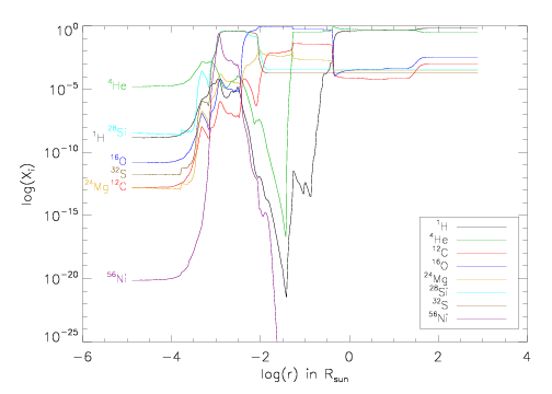
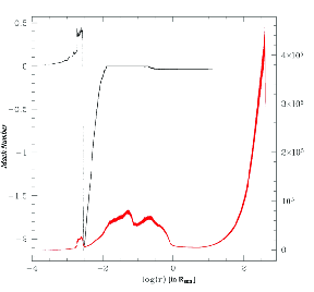
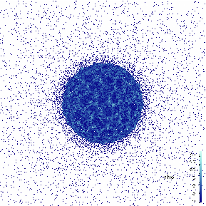
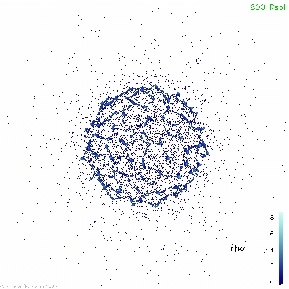
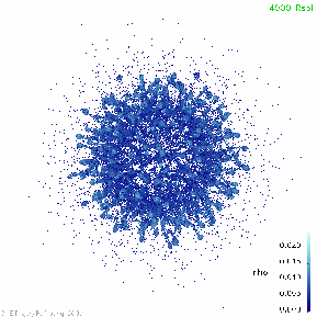


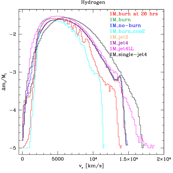
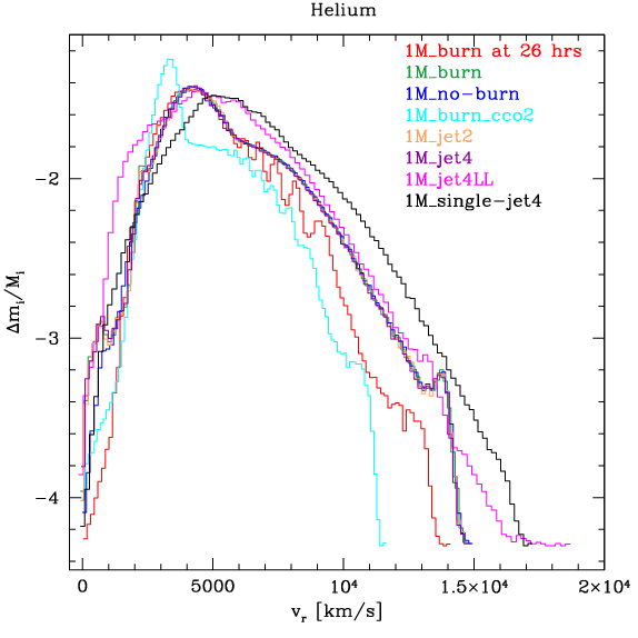

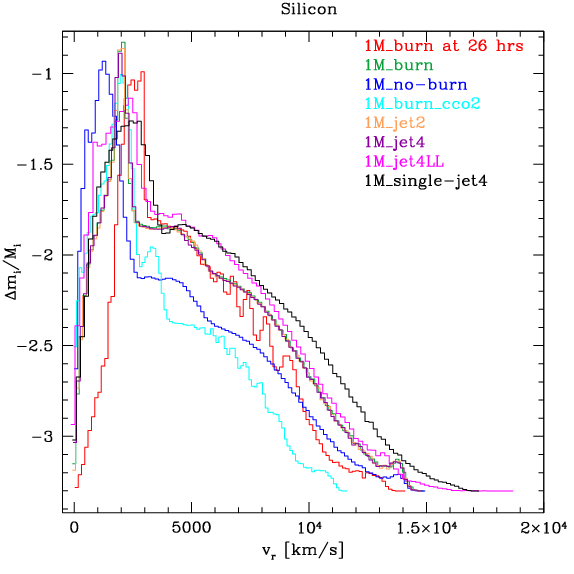
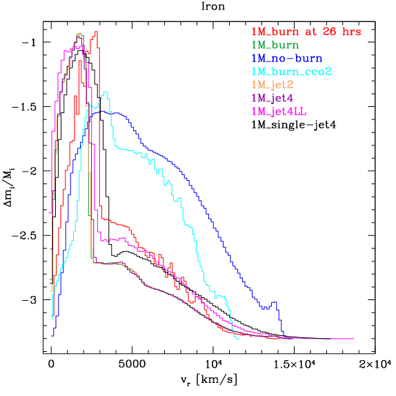
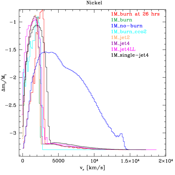
4 Structure Characteristics
4.1 Power Spectrum Analysis
Our primary aim in this work is to characterize the size distribution of clumps in the years following a supernova. In an effort to quantitatively describe the clump sizes, and in order to tell differences between the different runs, we calculated the power spectrum of the clumps sizes in each simulation.
The Fourier transform of a periodic signal in time decomposes that signal into its frequency components. Similarly, the Fourier transform of a periodic signal in space decomposes that signal into its wavenumber components. Thus, by treating the spatial data for the clumps as a signal that has a period equal to the size of the simulation, we can calculate the power spectrum of the wavenumbers of which it is composed and determine the corresponding wavelengths. The power spectrum versus wavelength will then show local maxima at the characteristic length scales (wavelengths) of the system, allowing us to infer typical sizes of clumps. The challenge is, since this method will pick up both the clumps as well as the spaces in between, to separate out the length scales of interest to us. Using the cross sectional data slices for the simulations can facilitate this. A related approach (e.g. WTA analysis, see Lopez et al., 2009b) has demonstrated its utility for interpreting observational data.
The Fourier transforms were calculated in IDL (Interactive Data Language) with the built-in FFT function. Since the RT fingers created overdense regions with a steep density gradient at the clump boundaries that makes them well defined, a density threshold was used to select that region. Although this brings with it the risk that the eventual size scales of these fingers are dependent on the density threshold chosen to select them, the density gradient is steep enough that we find this to introduce only small errors. Minor changes in the density threshold do not significantly affect the size of the chosen region. The density threshold was set high enough that most of the web-structure and filaments were avoided. However, for comparison we also analyzed one case with the filaments included (figure 28).
The Fourier transforms were taken by compressing slices of data through the 3D simulations to 2-dimensional images of pixels. The size of these image arrays was mainly determined by the largest 2D array that IDL would process. The ’sampling rate’ of the pixels must be chosen such that the Nyquist critical frequency () resolves the small scales we are interested in. Furthermore, our interest is in the short wavelength, large wavenumber regime, which is notorious for containing the noise in the transform. Furthermore, we have to be wary of any aliasing which may occur. Although IDL calculates the Fourier coefficients up to , frequencies higher than that may still be folded into the frequencies below the Nyquist frequency. However, the power approaches zero at the largest wavelengths in all our fourier transformed data, therefore it is likely that strong aliasing is not an issue.
In an effort to reduce edge effects and aliasing in the Fourier transforms, the image was set to correspond to a physical size on a side equal to the radius of the simulation at the given time snapshot. Thus, the sampling frequency was determined by the distance between two array elements/pixels, , where is the size of the image array in each dimension (4096) and R0 is the radius of the simulation as given by SNSPH. Thus, the Nyquist critical frequency is . The smallest length scale that can be resolved then is R0. We are expecting the typical sizes of the clumps on the order of 1% of the radius of the remnant, therefore we deem that resolution as sufficient.
For a clearer representation of the clumps, we transformed slices of the 3D simulations into a 2D image. This way, it is possible to almost completely avoid clumps close to a given line-of-sight being artificially merged together into one bigger clump in the conversion to the 2D image. When filling out the array, care needed to be taken to account for the non-zero size of the SPH particles. It was noted that some clumps contained artificial small gaps or holes. We deemed the gaps as artificial since they arose from SPH particles that did not make the cut into a slice, but nevertheless had a density contribution to it. We opted against using a smoothing algorithm to smooth out those features, as that would have introduced too much artificial noise into the data (and thus the transforms). Finally, the density in the clumps was set to 1 for this purpose to minimize the noise on pixel-to-pixel scale, and the pixels not containing part of a clump were set to zero. Each dimension (x,y,z) was divided into 30 slices, and the central slices were used to compute the Fourier transforms. For the symmetric runs, slices in only one plane were used; for the asymmetric runs, slices parallel and perpendicular to the asymmetry were used.
The power spectrum was computed for each transform by computing the sum squared amplitude at each pixel, , where is the power and is the (complex) value of the Fourier transform in the pixel of row , column . Before the calculation of the power, the computed FFT coefficients were normalized to set the zero frequency component to 1. The 2D power spectrum plots were then summed azimuthally (i.e. were binned into concentric annuli centered on the center of the 2D FFT array, and the values of the power in each annulus was summed, and plotted versus its corresponding wavelength). This improves the signal to noise at small wavelengths and provides an estimate of size scales for the entire remnant.
Figures 25– 34 show the results of the Fourier transforms of the slices through the simulations. The upper left and right panels in each figure shows the 2D image and the 2D power spectrum of the data versus wavenumber, both expanded around the origin to show detail. The second panel shows the summed power spectrum vs. wavelength over all length scales, and the third panel shows an expanded view of the power spectrum at small length scales. In each figure, the number of SPH particles considered in the Fourier analysis is indicated.
All plots show significant power at the short/shortest length scales, indicating the presence of small scale structure. In all simulations, the size scale for the shortest wavelengths indicated in all power spectrum plots is at to of the size (radius) of the remnant. While all runs show structure down to that smallest value, the higher end of that range tended to be populated by those runs that showed contribution from the filaments or stems to the clumps in the FFT plots. All FFT plots also show significant power at a length scale of of the respective remnant size, which corresponds to the diameter of the shell of clumps created by the fluid instabilities.
Figures 25, 26, and 27 show the FFT results for the canonical 1M, the 10M, and the 50M runs. All show a trough at R⊙ and a broad, shallow peak for length scales greater than that, and a number of narrow, tall peaks for length scales smaller than that. The broad peak at the largest wavelengths correlates with the size of the whole RT structure complex in the remnants. While the broad peak is very similar in each, there are differences in the narrow peaks in each simulation. The expanded views (panels 3) in each figure show that the canonical 1M run has a somewhat well defined peak centered at roughly 110 R⊙, while the 10M run shows a series of peaks (almost oscillations) with the first local maximum at 40 R⊙, and 50M run also shows a peak between 0 R⊙ – 200 R⊙ that is roughly Poisson-shaped and has a local maximum at 40 R⊙. It looks similar to the 1M run, but is much better defined and does not ”trail out” like the one in the 1M run. All three runs show another peak/ double peak centered at a length scale of R⊙, which seems to correlate to the inner diameter of the RT clump structure.
The zoomed-in panel of the FFT decomposition of the canonical run shows the peak(s) at the smallest wavelengths in detail. The maximum at 110 R⊙ mentioned above is associated with a somewhat well defined broader peak between 50 R⊙ and 150 R⊙, followed by another fairly well defined peak at slightly below 200 R⊙. Comparison with the slice through the original data suggests that the first peak (between 50 R⊙ – 200 R⊙) mostly corresponds to the density clumps, whereas the peaks following it likely corresponds mostly to the space in between those clumps.
Applying this comparison to the 10M_burn run is more difficult, since the space between clumps is closer to the size of the clumps there. Thus, the series of peaks for wavelengths greater than R⊙ likely is dominated by the length scales between two clumps, however, the length scales smaller than that, especially the peak at 40 R⊙, likely indicates size scales for the clumps themselves.
For the 50M_burn run a similar situation is encountered, although here it can be more convincingly argued that the first maximum at 40 R⊙ corresponds to the dominant size scale of the clumps. However, it is also true that using just a density threshold for selecting the clumps is less accurate than in the lower resolution runs for two reasons. The density contrast between the clumps and the filaments is less pronounced, and the RT fingers are more non-linear in this run (e.g. more bending and interacting is observed, as well as RT filaments growing out of the mushroom top of others). Thus, choosing a threshold high enough that only clumps are apparent only selects part of the RT clumps (i.e. the mushrooms caps). Lowering the threshold also selects most of the RT filaments (mushroom stems).
When the filaments are added into the FFT analysis, two main differences can be seen at small length scales. The first is that with the filaments, the broad peak at 0-200 R⊙ is much flatter, and has a narrow peak at R⊙ superposed on it. This peak seems to correlate with the typical spacing between the RT fingers. As the size of the clumps is very similar to the 10M_burn run, one would expect there to be a corresponding feature in the FFT decomposition, and indeed, small peaks at R⊙, R⊙, and R⊙ can be discerned (and actually, one finds in the data image that there are some clumps with approximately ellipsoidal cross sections, suggesting an oblate or prolate shape for some clumps). The second difference is that the peak between 450-650 R⊙ is much higher, higher in fact than the one at 0-200 R⊙. This peak, as well as the smaller one just inside of it (at R⊙) probably corresponds to the typical lengths of the filaments.
Comparing the FFT power spectra of the other runs to their respective data images in the same spirit, much of the same features are found. Comparing the Fourier transformed data of the 1M_no–burn run at each of three time snapshots shows that over time the maximum at small wavelengths that indicates the typical clump size becomes more apparent over time. This is because as the RT fingers grow, the density contrast between the mushroom caps constituting the RT clumps and the ambient gas increases. Thus, using a density threshold to select the overdense RT clumps is more accurate for the later times. While the RT fingers expand homologously and at the same rate with the rest of the remnant after a few days, they do not diffuse.
The power spectra of the run where the number of neighbors was varied also show very similar features. The peak at smallest wavelengths is composed of a series of peaks of very similar amplitude though; there is not any one peak that ”sticks out” above the others (very similar to the FFT spectrum of the 10M_burn run). This is more noticeable in the power spectrum for run 1M_burn_70nbrs, for which the data image shows clumps distributed in a narrow ring, resembling the fact that all RT fingers grew to approximately the same length. However, it is noted that the clump size in the data slices seems somewhat smaller than in the other 1 million particle runs; a corresponding feature can be seen in the respective power spectra as a small peak at R⊙. This value is similar to what is found for the 10M and 50M runs. All of these runs (1M_burn_38nbrs, 1M_burn_70nbrs, 10M_burn, 50M_burn) have a different initial conditions setup for particle distribution than the other 1M runs (all asymmetric 1M runs were based on 1M_burn). Any similarities we see in the small scale power spectrum are not artifacts of the problem setup.
The power spectra of the bipolar explosions, shown in figures 29 – 30) show some differences to the symmetric runs discussed above. The most obvious difference is a peak, constituting the global maximum in each plot, at R⊙, which itself features 3 spikes. At short wavelengths, the distribution of the structure is also different from the symmetric runs. Each of the bipolar runs show a series of distinct peaks out to R⊙, though the exact placement and shape of those peaks differ slightly among the bipolar runs. The three to four prominent peaks in the power spectra in that range likely mostly corresponds to the added spacings between the ring of clumps and those inside of it, and the ring of clumps and the RT clumps outside of it. The power at wavelengths shorter than that range is likely still determined by the typical sizes of the clumps (RT and otherwise). Overall, the main difference between the plots parallel and perpendicular to the polar axis is that those for the parallel case show a little less power at the shortest wavelengths. As the asymmetry is not very pronounced, it is probably reasonable that there is no major difference. It should be noted that in these simulations the Ni-bubble is clearly discernible in the data images, causing the different distributions of ’power’ at small length scales. The power in structures at these intermediate scales completely swamps any signal from the 100 R⊙ individual clump scale in the symmetric simulations.
The two late ”jet4” scenarios (run 1M_burn_jet4L and 1M_burn_jet4LL) in the following plots (figures 31 – 32) also show the 3-spiked peak at large wave lengths, but shifted inward to R⊙ as these simulations were followed to only 0.1 yrs after the explosion. The distribution at short length scales is again in several narrow distinct peaks, similar to the ’early’ bipolar asymmetries discussed above. It should be noted that in the run 1M_burn_jet4LL the density contrast between the RT clumps and the ambient gas (including the filaments) was not very large, thus the density threshold necessary to select mostly complete clumps again selected most of the RT filaments as well. Thus the Fourier transformed data is dominated by those features (between R⊙), and most of the power that is present at smallest length scales is likely due to the small spaces between the RT features.
Finally, the single-lobe asymmetries show similarities to the bipolar scenarios. This is not too surprising, since, to first order, the main difference between those is the number of lobes in the asymmetry, and secondly, the dominant feature at this point in each of those simulations is the shell of clumps generated by the Ni-bubble.
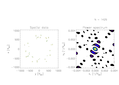
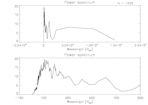
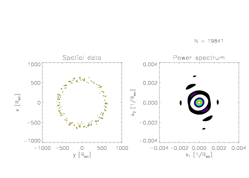
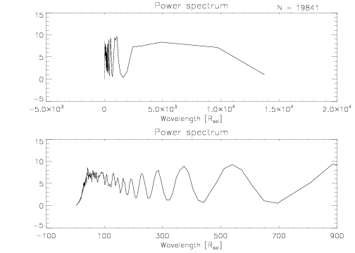
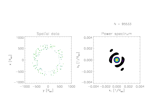
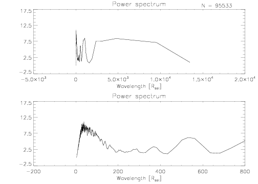
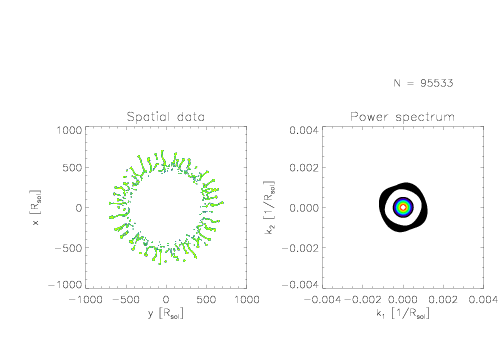
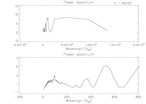
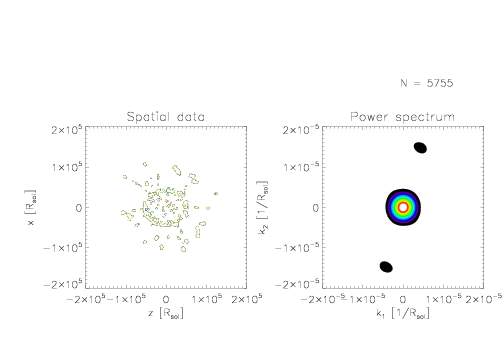
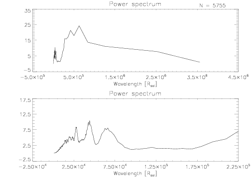
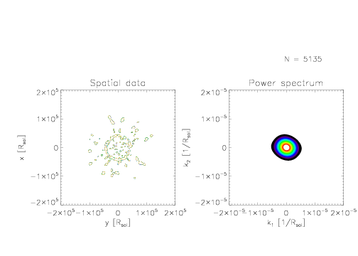
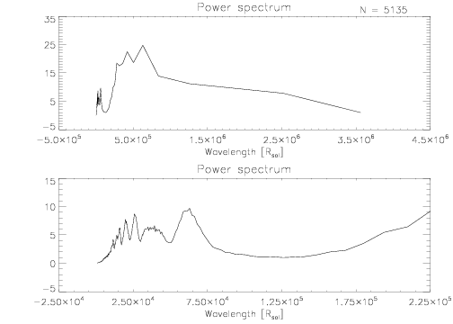
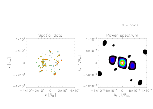

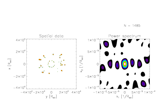
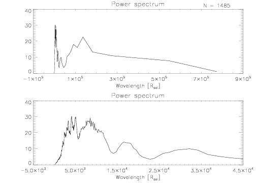
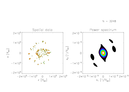
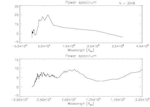
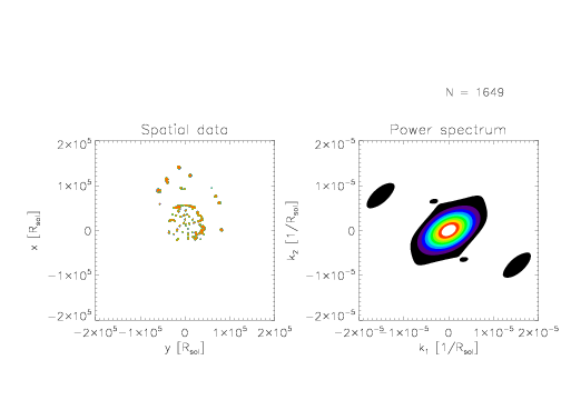
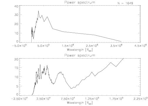
5 Conclusion
It is well established that instabilities readily arise in supernova simulations, and grow to form distinct structures. Differences appear between groups, and between different simulations from a single group. The behavior is affected by the choice of progenitor model, how the explosion is handled, the presence of initial perturbations, resolution, and dimensionality. We perform simulations of explosions of a 15 M⊙ progenitor to determine the behavior of our code when producing instability-related small scale structures (as opposed to global asymmetries) and comparing it to previous work. We also develop a power spectrum formalism for quantifying the size scales of structures in the explosion. Both of these topics are groundwork for extending our simulations to the supernova remnant phase, including adding new physics such as x-ray cooling. The final goal of this work is to identify the origin of structures observed in young supernova remnants and predict their properties over the evolution of the SNR.
Rayleigh-Taylor instabilities are effective at creating numerous clumps of predominantly He, C, and O in our simulations of supernova explosions. These clumps form at the terminal ends of RT spikes developing in the explosion, and are initially at least one order of magnitude denser than the SN ejecta they grow into. Their size scales range from – of the size (diameter) of the remnant, which is about 1-2 orders of magnitude bigger than the x-ray ejecta knots found in Cas A. Their size relative to the remnant is around . Therefore, the RT clumps probably are not the ejecta knots, but they may well be related, possibly evolving into them as the remnant ages and cooling fragments the clumps.
We have considered the feasibility of RT mode that is set up in each run in various aspects, and concluded that the mode of the instability is likely approximately resolved in the 50 million particle run, and just under-resolved in the 1 and 10 million particle runs. We found that the size of the RT clumps decreases when increasing the resolution to 10M, but stays approximately the same increasing the resolution further to 50M. We determined that the occurrence of the instability is due to physical processes, rather than numerical artifacts, and thus find SNSPH a useful and suitable tool for the study of formation and further evolution of small scale structure in the explosion of SNe. We are aware, however, of the limitations of standard SPH formulations to resolve KH instabilities, which become important in the non-linear growth phase of the RT plumes. Improvements to SPH codes in the form of additional correction terms have been published and verified in the literature (e.g. Balsara, 1995; Price, 2008), which we intend to implement and test as a next step in our endeavor.
Plumes form at the OC/He interface in our simulations, as most other groups have found also. We see RT fingers forming at only one interface, not two or three, although the evolution of the velocity profile suggests that other interfaces briefly enter an instability. As in Kifonidis et al. (2003), we see a dense shell of He-rich material piling up as the shock enters the H-envelope, however in our simulation this pile-up of material results in RT instabilities, and not in a ”wall” confining the RT plumes inside of it.
In the absence of a surrounding medium that would eventually interact with the ejecta, the RT filaments and clumps are permanent features. Our simulations show that the clumps detach from the ends of the filaments. At the point in its evolution when the ejecta gas has expanded into the optically thin regime, it can efficiently cool by radiation from electronic transitions. This cooling should contribute further to the condensation and fragmentation of the clumps into sub-clumps as the clumps depart from pressure equilibrium with the surrounding medium. Inclusion of a mass loss-generated circumstellar environment or ISM in the calculations is not expected to destroy the clumps, but it will have a significant effect on them. As the SN gas expands, it sweeps up surrounding material, eventually creating a dense shell with which it will interact at some point. A reverse shock that arises eventually from this interaction travels back through the ejecta, and will compress and heat the RT clumps. Rapid cooling should result in fragmentation and increased density in the clumps. and shocks probably shred them into smaller pieces. This process can be seen acting on optical ejecta knots in Cas A in multiple epochs of HST observation.
Dense bullets are also observed in some scenarios in the regions interior to of the RT fingers. 56Ni produced in the explosion is abundant in this central region, which, if it does not fall back onto the central compact object, it heats through its decay to Co and Fe. Thus, the Ni-rich region expands and compresses the regions without (much) Ni. O, He, and H, which has been mixed down into the Ni region, is compressed into dense clumps, which in all simulations in which they occur end up slightly exceeding the density in the RT clumps. No significant Ni-bubble was observed in the CCO runs since a majority of the Ni that was produced fell back onto the compact remnant.
Neither of these clumps appear to contain much Fe-group material. 44Ti, closely following the distribution of 56Ni, is in the part of the Ni-bubble that expands, and does not become mixed into the bullets/clumps in that region. Artificial asymmetries can mix some Fe- group elements closer to the RT fingers, but not significantly into the RT flow. Only in the most extreme imposed asymmetry (the 1M_jet4LL scenario) and fallback– induced convection (runs 1M_burn_CCO and -CCO2) are the RT fingers affected by the asymmetry. In the 1M_jet4LL scenario, RT fingers are significantly elongated along the polar axis, while they are nearly absent at the equator. In the two runs including the central compact object the central convection imparts a global, low mode asymmetry on the remnant after the RT fingers have formed, and mostly affects the central distribution of elements. In general, though, the formation of RT instabilities seems to be quite insensitive to the mode of any global asymmetry.
We find that our explosion simulations produce instability-related structures qualitatively similar to those found by other groups. These simulations are suitable precursors to further calculation of SNR evolution with cooling and CSM interaction. We can create quantitative predictions of the distribution of sizes of over dense structures in the remnant which are suitable for with similar analyses of observations.
Acknowledgements This work was supported by NSF grant #0807567 and The NASA Astrobiology Institute. The simulations were performed on the Dell linux cluster of the High Performance Computing Initiative at Arizona State University. The authors thank the anonymous referee for a constructive review that helped to improve the paper.
References
- Agertz et al. (2007) Agertz, O., Moore, B., Stadel, J., Potter, D., Miniati, F., Read, J., Mayer, L., Gawryszczak, A., Kravtsov, A., Nordlund, Å., Pearce, F., Quilis, V., Rudd, D., Springel, V., Stone, J., Tasker, E., Teyssier, R., Wadsley, J., and Walder, R.: 2007, MNRAS, 380, 963
- Arnett et al. (1989) Arnett, D., Fryxell, B., and Müller, E.: 1989, ApJL, 341, L63
- Arnett et al. (2009) Arnett, D., Meakin, C., and Young, P. A.: 2009, ApJ, 690, 1715
- Arnett and Meakin (2011) Arnett, W. D. and Meakin, C.: 2011, ApJ, 733, 78
- Balsara (1995) Balsara, D. S.: 1995, Journal of Computational Physics 121, 357
- Bazan and Arnett (1998) Bazan, G. and Arnett, D.: 1998, ApJ, 496, 316
- Benz et al. (1989) Benz, W., Thielemann, F.-K., and Hills, J. G.: 1989, ApJ, 342, 986
- Bloecker (1995) Bloecker, T.: 1995, A&A, 297, 727
- Blondin and Mezzacappa (2006) Blondin, J. M. and Mezzacappa, A.: 2006, ApJ, 642, 401
- Blondin et al. (2003) Blondin, J. M., Mezzacappa, A., and DeMarino, C.: 2003, ApJ, 584, 971
- Buras et al. (2003) Buras, R., Rampp, M., Janka, H.-T., and Kifonidis, K.: 2003, Physical Review Letters 90(24), 241101
- Burrows et al. (1995) Burrows, A., Hayes, J., and Fryxell, B. A.: 1995, ApJ, 450, 830
- Burrows et al. (2006) Burrows, A., Livne, E., Dessart, L., Ott, C. D., and Murphy, J.: 2006, ApJ, 640, 878
- Erickson et al. (1988) Erickson, E. F., Haas, M. R., Colgan, S. W. J., Lord, S. D., Burton, M. G., Wolf, J., Hollenbach, D. J., and Werner, M.: 1988, ApJL, 330, L39
- Fryer et al. (1998) Fryer, C., Burrows, A., and Benz, W.: 1998, ApJ, 496, 333
- Fryer (1999) Fryer, C. L.: 1999, ApJ, 522, 413
- Fryer et al. (2007a) Fryer, C. L., Hungerford, A. L., and Rockefeller, G.: 2007a, International Journal of Modern Physics D 16, 941
- Fryer et al. (2007b) Fryer, C. L., Mazzali, P. A., Prochaska, J., Cappellaro, E., Panaitescu, A., Berger, E., van Putten, M., van den Heuvel, E. P. J., Young, P., Hungerford, A., Rockefeller, G., Yoon, S.-C., Podsiadlowski, P., Nomoto, K., Chevalier, R., Schmidt, B., and Kulkarni, S.: 2007b, PASP, 119, 1211
- Fryer et al. (2006) Fryer, C. L., Rockefeller, G., and Warren, M. S.: 2006, ApJ, 643, 292
- Fryer and Warren (2002) Fryer, C. L. and Warren, M. S.: 2002, ApJL, 574, L65
- Fryer and Young (2007) Fryer, C. L. and Young, P. A.: 2007, ApJ, 659, 1438
- Fryxell et al. (1991) Fryxell, B., Arnett, D., and Müller, E.: 1991, ApJ, 367, 619
- Graboske et al. (1973) Graboske, H. C., Dewitt, H. E., Grossman, A. S., and Cooper, M. S.: 1973, ApJ, 181, 457
- Hachisu et al. (1991) Hachisu, I., Matsuda, T., Nomoto, K., and Shigeyama, T.: 1991, ApJL, 368, L27
- Hachisu et al. (1992) Hachisu, I., Matsuda, T., Nomoto, K., and Shigeyama, T.: 1992, ApJ, 390, 230
- Hammer et al. (2010) Hammer, N. J., Janka, H., and Müller, E.: 2010, ApJ, 714, 1371
- Herant (1995) Herant, M.: 1995, Phys. Rep. 256, 117
- Herant and Benz (1991) Herant, M. and Benz, W.: 1991, ApJL, 370, L81
- Herant and Benz (1992) Herant, M. and Benz, W.: 1992, ApJ, 387, 294
- Herant et al. (1992) Herant, M., Benz, W., and Colgate, S.: 1992, ApJ, 395, 642
- Herant et al. (1994) Herant, M., Benz, W., Hix, W. R., Fryer, C. L., and Colgate, S. A.: 1994, ApJ, 435, 339
- Hoeflich (1988) Hoeflich, P.: 1988, Proceedings of the Astronomical Society of Australia 7, 434
- Hungerford et al. (2005) Hungerford, A. L., Fryer, C. L., and Rockefeller, G.: 2005, ApJ, 635, 487
- Hungerford et al. (2003) Hungerford, A. L., Fryer, C. L., and Warren, M. S.: 2003, ApJ, 594, 390
- Joggerst et al. (2010a) Joggerst, C. C., Almgren, A., Bell, J., Heger, A., Whalen, D., and Woosley, S. E.: 2010a, ApJ, 709, 11
- Joggerst et al. (2010b) Joggerst, C. C., Almgren, A., and Woosley, S. E.: 2010b, ApJ, 723, 353
- Joggerst et al. (2009) Joggerst, C. C., Woosley, S. E., and Heger, A.: 2009, ApJ, 693, 1780
- Junk et al. (2010) Junk, V., Walch, S., Heitsch, F., Burkert, A., Wetzstein, M., Schartmann, M., and Price, D.: 2010, MNRAS, 407, 1933
- Kane et al. (2000) Kane, J., Arnett, D., Remington, B. A., Glendinning, S. G., Bazán, G., Müller, E., Fryxell, B. A., and Teyssier, R.: 2000, ApJ, 528, 989
- Kifonidis et al. (2003) Kifonidis, K., Plewa, T., Janka, H., and Müller, E.: 2003, A&A, 408, 621
- Kifonidis et al. (2006) Kifonidis, K., Plewa, T., Scheck, L., Janka, H.-T., and Müller, E.: 2006, A&A, 453, 661
- Kudritzki et al. (1989) Kudritzki, R. P., Pauldrach, A., Puls, J., and Abbott, D. C.: 1989, A&A, 219, 205
- Lamers and Nugis (2002) Lamers, H. J. G. L. M. and Nugis, T.: 2002, A&A, 395, L1
- Langanke and Martínez-Pinedo (2000) Langanke, K. and Martínez-Pinedo, G.: 2000, Nuclear Physics A 673, 481
- Lopez et al. (2009a) Lopez, L. A., Ramirez-Ruiz, E., Badenes, C., Huppenkothen, D., Jeltema, T. E., and Pooley, D. A.: 2009a, ApJL, 706, L106
- Lopez et al. (2009b) Lopez, L. A., Ramirez-Ruiz, E., Pooley, D. A., and Jeltema, T. E.: 2009b, ApJ, 691, 875
- Mezzacappa et al. (1998) Mezzacappa, A., Calder, A. C., Bruenn, S. W., Blondin, J. M., Guidry, M. W., Strayer, M. R., and Umar, A. S.: 1998, ApJ, 493, 848
- Müller et al. (1991) Müller, E., Fryxell, B., and Arnett, D.: 1991, A&A, 251, 505
- Müller et al. (1989) Müller, E., Hillebrandt, W., Orio, M., Hoflich, P., Monchmeyer, R., and Fryxell, B. A.: 1989, A&A, 220, 167
- Nagataki et al. (1998) Nagataki, S., Shimizu, T. M., and Sato, K.: 1998, ApJ, 495, 413
- Nordhaus et al. (2010) Nordhaus, J., Brandt, T. D., Burrows, A., Livne, E., and Ott, C. D.: 2010, Physical Review: D, 82(10), 103016
- Price (2008) Price, D. J.: 2008, Journal of Computational Physics 227, 10040
- Rauscher and Thielemann (2001) Rauscher, T. and Thielemann, F.-K.: 2001, Atomic Data and Nuclear Data Tables 79, 47
- Scheck et al. (2004) Scheck, L., Plewa, T., Janka, H.-T., Kifonidis, K., and Müller, E.: 2004, Physical Review Letters 92(1), 011103
- Shigeyama et al. (1988) Shigeyama, T., Nomoto, K., and Hashimoto, M.: 1988, A&A, 196, 141
- Wang and Wheeler (2008) Wang, L. and Wheeler, J. C.: 2008, ARA&A, 46, 433
- Witteborn et al. (1989) Witteborn, F. C., Bregman, J. D., Wooden, D. H., Pinto, P. A., Rank, D. M., Woosley, S. E., and Cohen, M.: 1989, ApJL, 338, L9
- Woosley (1988) Woosley, S. E.: 1988, ApJ, 330, 218
- Young and Arnett (2005) Young, P. A. and Arnett, D.: 2005, ApJ, 618, 908
- Young and Fryer (2007) Young, P. A. and Fryer, C. L.: 2007, ApJ, 664, 1033
- Young et al. (2005) Young, P. A., Meakin, C., Arnett, D., and Fryer, C. L.: 2005, ApJL, 629, L101