Spin-dependent Seebeck coefficients of Ni80Fe20 and Co in nanopillar spin valves
Abstract
We have experimentally determined the spin-dependent Seebeck coefficient of permalloy (Ni80Fe20) and cobalt (Co) using nanopillar spin valve devices. The devices were specifically designed to completely separate heat related effects from charge related effects. A pure heat current through the nanopillar spin valve, a stack of two ferromagnetic layers (F) separated by a non-magnetic layer (N), leads to a thermovoltage proportional to the spin-dependent Seebeck coefficient of the ferromagnet, where and are the Seebeck coefficient for spin-up and spin-down electrons. By using a three-dimensional finite-element model (3D-FEM) based on spin-dependent thermoelectric theory, whose input material parameters were measured in separate devices, we were able to accurately determine a spin-dependent Seebeck coefficient of 1.8 V K-1 and 4.5 V K-1 for cobalt and permalloy, respectively corresponding to a Seebeck coefficient polarization of 0.08 and 0.25, where is the Seebeck coefficient of the ferromagnet. The results are in agreement with earlier theoretical work in Co/Cu multilayers and spin-dependent Seebeck and spin-dependent Peltier measurements in Ni80Fe20/Cu spin valve structures.
pacs:
72.15.Jf, 72.25.-b, 85.75.-d, 85.80.-b, 72.25.Ba, 75.75.-c, 85.75.BbI Introduction
The interplay between spin and heat transport in magnetic structures is studied in the emerging field called spin caloritronics.Bauer et al. (2010, 2012) This subfield of spintronics has recently gained a lot of interest leading to notable experimentalUchida et al. (2008a); Le Breton et al. (2011); Walter et al. (2011); Slachter et al. (2010); Flipse et al. (2012); Yu et al. (2010) and theoretical studies.Hatami et al. (2009); Scharf et al. (2012) At the heart of spin caloritronics lie the spin-dependent Seebeck and related spin-dependent Peltier effect. The spin-dependent Seebeck effect describes thermally driven spin injection from a ferromagnet (F) into a non-magnetic (N) material when the F/N interface is subjected to a temperature gradient. This effect is governed by the difference in the Seebeck coefficients of spin-up electrons and spin-down electrons . Slachter et al.Slachter et al. (2010) demonstrated the spin-dependent Seebeck effect in Ni80Fe20/Cu lateral spin valve devices from which a spin-dependent Seebeck coefficient of 3.8 V K-1 was extracted using a 3D-FEM. Here it is important to point out the fundamental difference between the spin-dependent Seebeck and the so called ‘spin Seebeck effect’.Uchida et al. (2008b) Whereas the spin-dependent Seebeck effect is purely electronic in nature, the latter is now understood to originate from collective effects involving non-equilibrium thermally induced spin pumping due to temperature differences between, for example, conductions electrons and magnons.Xiao et al. (2010); Bauer et al. (2012)
The spin-dependent Peltier effect, which is the reciprocal of the spin-dependent Seebeck effect, describes heating/cooling of a F/N interface by a spin current. More recently, Flipse et al.Flipse et al. (2012) demonstrated the spin-dependent Peltier effect in Ni80Fe20/Cu/Ni80Fe20 nanopillar spin valve devices from which a spin-dependent Peltier coefficient of 1.1 mV was obtained. The spin-dependent Seebeck and Peltier coefficient reported in Refs. Slachter et al., 2010 and Flipse et al., 2012 follow the ThomsonOnsager relation , where is the temperature.
Although the concept of the spin-dependency of the Seebeck coefficient was first discussed by Campbell et al.Campbell and Fert (1982) and later used to explain large magnetothermoelectric powers in multilayers of Co/Cu Shi et al. (1993); Baily et al. (2000); Gravier et al. (2004), reports on the Seebeck coefficient polarization = are relatively scarce. For Ni80Fe20, a of 0.20 has been reported from spin-dependent SeebeckSlachter et al. (2010) and spin-dependent PeltierFlipse et al. (2012) measurements. In case of Co, effective values ranging from 0.18Gravier et al. (2006, 2004) to 0.42Shi et al. (1993); Cadeville and Roussel (1971) were reported from thermopower measurements in Co/Cu multilayers and diluted Co alloys, respectively. To quantify the size of spin caloritronic effects, one needs to accurately determine spin-dependent thermoelectric coefficients. In this paper, therefore, we provide absolute values of the spin-dependent Seebeck coefficient and its polarization for cobalt and permalloy from spin-dependent Seebeck measurements in F/N/F pillar spin valve devices.
The objectives of this paper are therefore twofold. First, it describes the spin-dependent Seebeck effect in specifically designed nanopillar spin valve devices. Secondly, it presents an accurate determination of the spin-dependent Seebeck coefficients for Ni80Fe20 and Co using a 3D-FEM. To that end, the electrical conductivity and Seebeck coefficient of all materials were measured in separate devices. The thermal conductivity of the thin metallic films was obtained from the measured electrical conductivity by using the Wiedemann-Franz law.Bakker et al. (2012) Thermal conductivity of insulating layers was determined from heat transport measurements across metal/insulator/metal structures.
This paper is organized as follows. In sec. II, we present general spin-dependent thermoelectrics in the framework of the two spin channel model and particularly explain thermally driven spin injection in symmetric F/N/F nanopillar devices. We also discuss the improvements to the 3D-FEM in terms of separately measuring the inputs material parameters. Sec. III presents details of the device fabrication and measurement schemes used in this study. Here we also explain how we achieve a temperature gradient over the F/N/F stack and present the two types of measurements that were performed to fully characterize the devices. Sec. IV presents the results of the electrical and thermal spin injection experiments and discuss how the polarization of the conductivity and of the Seebeck coefficient were extracted using the 3D-FEM. Finally, Sec. V presents the conclusions.
II Spin-dependent Seebeck effect in F/N/F pillar spin valve
In metallic ferromagnets, charge, spin and heat transport can be described by two parallel spin channels, one for spin-up () and another for spin-down () electrons, with each spin channel having its own conductivity and Seebeck coefficient .MacDonald (2006); Campbell and Fert (1982) The charge and heat current in each spin channel are related to their respective potential gradient and temperature gradient as Slachter et al. (2010)
| (1) |
where and are the Peltier coefficient and electrochemical potential for spin-up and spin-down electrons and is the thermal conductivity. Equation (1) is the basis for our 3D-FEM, which was previously used to describe spintronic and spin caloritronic phenomena. A detailed procedure for the modeling can be found in Ref. Slachter et al., 2011a. By separately measuring the modeling parameters for each material in dedicated devicesBakker et al. (2012), good agreement between the model and the measurement was obtained allowing us to accurately determine the spin-dependent Seebeck coefficients by using the measured electrical and thermal spin signals.
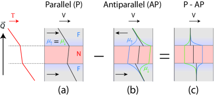
In the following, we describe the spin-dependent Seebeck effect in a symmetric F/N/F pillar stack with equal layer thicknesses (=15 nm) comparable to the spin relaxation length in the ferromagnet () but much smaller than in the non-magnetic layer (=300 nm). In a ferromagnet, owing to the difference in the spin-dependent Seebeck coefficients , a temperature gradient across a F/N interface drives a spin current from the F– into the N–regionSlachter et al. (2010) thereby creating a non-equilibrium spin-accumulation , which is proportional to the spin-dependent Seebeck coefficient of the ferromagnet. Here, we define spin-up electrons as the spins with the higher conductivity, which in case of both permalloy and cobalt are the majority spins. For a F/N/F pillar stack in a temperature gradient, thermal spin injection at the the two F/N interfaces results in a spin accumulation in the N–region that is a function of the relative alignment of the magnetization of the ferromagnets.
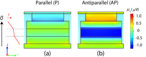
In the parallel () configuration (Fig. 1(a)), spins are injected at the first interface while being extracted at the second resulting in a flow of constant spin current across the whole stack. This constant spin current flow dictates that there is negligible spin accumulation at the two F/N interfaces, that is, the individual spin chemical potentials and are equal. In the antiparallel configuration (), however, spins of similar kind are injected from both interfaces into the N–region. In such configuration, the spin current in the bulk of the ferromagnets is opposite to each other giving rise to a large spin accumulation in the N–region. This large spin accumulation results in the splitting of the spin electrochemical potentials (see Fig. 1(b)). A cross-sectional plot of the spin accumulation obtained from the three-dimensional FEM (shown in Fig. 2) demonstrates the significant difference in the size of the spin accumulation for the two different configurations.
An expression for , based on one–dimensional spin-diffusion equation, in the limit ,, can be found elsewhere.Scharf et al. (2012); Slachter et al. (2010) Here we extend this limit to devices with thicknesses comparable to and and find the expression given in Eq. 9 of the appendix, which is similar to the expression in Ref. Slachter et al., 2010 except for the resistance mismatch factor. The interfacial spin thermoelectric voltage drop , which is different for the two configurations, can then be expressed as a function of the spin accumulation at the two F/N interfaces. In an experiment, one measures this open-circuit thermovoltage as a function of an external magnetic field. The spin valve signal ()/e is thus given by:
| (2) |
where is the temperature gradient in the F-region. The term denotes the resistance mismatch factor for a symmetric spin valve given by:
| (3) |
where and are the spin-resistances of the ferromagnet and the normal metal. In the limit ,, reduces to the single F/N interface result which is often close to one. Note, however, that in the analysis we use the numerical results from the three-dimensional finite element modeling based on Eq. 1 to extract and .
III Experiments
The nanopillar spin valve devices were prepared in one optical lithography step followed by nine electron-beam lithography (EBL) steps. Materials were deposited by e-beam evaporation at a base pressure of Torr on a thermally oxidized Si substrate with a 300-nm-thick oxide layer. Fig. 3(a) and Fig. 3(b) show a schematic and scanning electron microscope image of the measured device. The device consists of a F/N/F stack sandwiched between a bottom and top contact. The experimental methods and device fabrications are similar to the ones reported in Ref. Flipse et al., 2012.
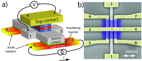
First, a pair of 40-nm-thick Pt Joule heaters, which are 400 nm apart, were deposited. Then an 8-nm-thick AlOx layer was deposited over the sides and surfaces of the Pt Joule heaters followed by the deposition of the bottom contact (60-nm-thick Pt). The AlOx barriers electrically isolate the bottom contact from the Pt-heaters to avoid charge related effects. Then, the nanopillar spin valve with a structure F(15)/Cu(15)/F(15)/Au(10), where FNi80Fe20 or Co and the number between the parentheses are the thicknesses in nanometers, was deposited without breaking the vacuum of the deposition chamber to obtain clean interfaces. In the next two EBL steps, a top contact hole was defined followed by crosslinking a polymethyl methacrylate (PMMA) matrix around the nanopillar to isolate the bottom contact from the top contact. Finally, the top contact (130-nm-thick Au) was deposited.
The measurements presented in this paper are all performed at room temperature using standard lock-in techniques. A low frequency (=17 Hz) ac-current II0sin was used for the measurements to allow for efficient thermalization and a steady state condition. To fully characterize the samples, two different measurements were performed. First, in the spin valve measurements, the four-probe resistance of the nanopillar was measured as a function of magnetic field. To that end, a 0.1 mA current was sent through the nanopillar from contact 3 to 4 while the voltage is measured using contacts 1 and 2. From the spin valve signal, the bulk spin polarization , which is later used in the determination of , was extracted. In thermal spin injection measurements, the open-circuit voltage across the nanopillar was measured using contacts 1 and 2 while a current of 1 mA was sent through the Pt Joule heaters (contacts 5-6 and 7-8). The measured voltage was fed to two different lock-in amplifiers which were set to record the first harmonic and second harmonic responses of the signal. In the spin valve measurement, we looked at the voltage while in the thermal spin injection measurements we were mainly interested in the component of the measured voltage since the spin-dependent Seebeck effect scales with the temperature gradient .Slachter et al. (2010); Bakker et al. (2010); Flipse et al. (2012)
IV Results and discussion
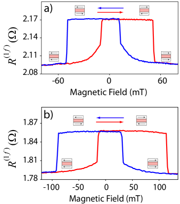
Fig. 4 shows the four-probe resistance measurements for Ni80Fe20 and Co nanopillar pillar devices as a function of the in-plane magnetic field. The spin valve signal is defined as =, where and are the resistance of the pillar in the parallel and antiparallel configurations, respectively. For Ni80Fe20 (Fig. 4(a)), a spin valve signal of 75 m was observed on top of a background resistance, +)/2, of 2.13 . By using the measured spin signal as the only fitting parameter in the 3D-FEM, a conductivity polarization of 0.46 was extracted, which is in agreement with Andreev reflection measurements.R. J. Soulen et al. (1999) The calculated background resistance of 1.77 calculated with the finite element model is in reasonable agreement with the measured background resistance.
The input parameters to the finite element model, which are , S, and , were all know from measurements in separate dedicated devices. The spin relaxation lengths for Ni80Fe20 and Co were obtained from Ref. [][; andreferencestherein.]bass_spin-diffusion_2007. We used a spin relaxation length of 5 nm for Ni80Fe20 and 40 nm for Co, respectively. These values were systematically chosen by calculating the spin signal for different values of spin relaxation lengths and fitting it to the measured spin signals (See Fig. 8 in Sec. C).
Following similar analysis procedure for Co (Fig. 4(b)), from a spin signal of 60 m, we found a conductivity polarization 0.45 in agreement with Andreev reflection measurements in metallic point contactsR. J. Soulen et al. (1999) and values reported elsewhereGravier et al. (2006). The background resistance, 1.82 , obtained from the measurement is a factor of two higher than the calculated background resistance of 0.99 . This points to the presence of a possible interfacial resistance at the bottom Pt/Co or top Co/Au interfaces, which can effectively increase the resistance of the stack. Such resistive layer may arise, for example, from interfacial disorder due to some lattice mismatch, atomic or magnetic disorders.Tsymbal and Zutic (2011) If we account for such interfacial resistance, for a conductivity polarization 0.52, we obtain a background resistance of 1.5 and a spin valve signal of 56 m in good agreement with the measurement.
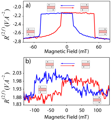
Fig. 5 shows the spin-dependent Seebeck measurements for a charge current of 1 mA through each Pt Joule heaters (contacts 5 to 6 and 7 to 8) in opposite directions. The heat generated from the dissipated power in the Pt Joule heaters diffuses through the AlOx insulating barrier and heats the bottom of the nanopillar thereby creating a temperature gradient over the stack. The temperature gradient across the pillar creates a Seebeck voltage that depends on the relative orientation of the two magnetizations in the nanopillar.
| Sample | |||||||||
|---|---|---|---|---|---|---|---|---|---|
| (m) | (V A-2) | () | () | (V A-2) | (V A-2) | (V K-1) | |||
| Py (Presented in main text) | -75 | -0.60 | 2.12 | 1.77 | -2.4 | -2.43 | 0.46 | 0.25 | -4.50 |
| Py1 | -61 | -0.70 | 1.85 | 1.76 | -4.0 | -2.48 | 0.42 | 0.26 | -4.68 |
| Py2 | -70 | -0.60 | 2.26 | 1.76 | -3.9 | -2.42 | 0.45 | 0.25 | -4.50 |
| Py3 | -80 | -0.65 | 1.90 | 1.77 | -4.0 | -2.45 | 0.47 | 0.25 | -4.50 |
| Co (Presented in main text) | -60 | -0.12 | 1.82 | 0.99 | 1.93 | 6.23 | 0.45 | 0.07 | -1.68 |
| Co1 | -60 | -0.12 | 1.89 | 0.99 | 1.64 | 6.23 | 0.45 | 0.07 | -1.68 |
| Co2 | -62 | -0.13 | 1.82 | 0.99 | 2.0 | 6.28 | 0.45 | 0.08 | -1.92 |
| Co3 | -65 | -0.12 | 1.83 | 1.02 | 1.95 | 6.23 | 0.46 | 0.07 | -1.68 |
For Ni80Fe20 (Fig. 5(a)), a spin-dependent Seebeck signal of 0.6 VA-2 was measured on top of a background resistance 2.4 VA-2. From the measured spin signal, we obtain a spin-dependent Seebeck coefficient of 4.5 V K-1 corresponding to a Seebeck coefficient polarization of 0.25 in agreement with previous reportsSlachter et al. (2010); Flipse et al. (2012), where ()/.Slachter et al. (2010); Flipse et al. (2012) The negative sign indicates that the Seebeck coefficient of spin-up electrons, which are the majority spins in Ni80Fe20 and Co, is more negative than that of the spin-down electrons. The calculated background resistance of 2.43 V A-2 is in good agreement with the measured background resistance.
For cobalt (Fig. 5(b)), for a heating current of 1 mA, a spin signal of 0.12 V A-2 was obtained. Similar analysis gives a spin-dependent Seebeck coefficient of 1.7 V K-1 that corresponds to a Seebeck polarization 0.07. This result is comparable with a tight-binding calculation of the Seebeck coefficient of Co/Cu multilayersTsymbal et al. (1999) where, from the energy derivative of and Mott’s relation for the Seebeck coefficient, a Seebeck coefficient difference of 1.76 V K-1 between the parallel and antiparallel configurations was obtained. The measured background resistance of 1.93 V A-2 is lower than the calculated of 6.23 VA-2. This discrepancy can be again attributed to the extra interfacial resistive layer that can modify the heat current (temperature profile) across the stack. Taking this interfacial thermal resistance in to account, we obtain a background resistance of 2.4 V A-2 in good agreement with the measurement. The Seebeck coefficient polarization of 0.14 obtained is however two times higher than that obtained without including the interfacial resistance (0.07).
In Fig. 5(b), there exists a visible asymmetry in the two parallel configurations due to possible contributions from spin-orbit effects like the anomalous Nernst effect.Slachter et al. (2011b)
The results presented above were for two samples, one for Ni80Fe20 and one for Co, from a total of eight samples which were measured in a similar manner. Table 1 shows the measurement results of the remaining six samples. The polarization of the conductivity and Seebeck coefficient were extracted by fitting the measured spin signals to the 3D-FEM. The modeled background resistances, which are shown in shaded columns, are in reasonably good agreement with the measurements and are consistent with the samples presented in the text.
V Conclusion
In summary, we have performed all-electrical spin-dependent Seebeck effect measurements in Ni80Fe20 and Co nanopillar spin valve devices. We found that the polarization of the Seebeck coefficient for Ni80Fe20 (25%) and Co (8%) are in agreement with earlier experimental studies in Ni80Fe20/Cu spin valve structures and earlier theoretical works in Co/Cu multilayers, respectively. With the method presented here, it is in principle possible to measure the polarization of the conductivity and Seebeck coefficient of any ferromagnetic metal that makes up a symmetric or asymmetric spin valve.
Acknowledgements.
The authors thank B. Wolfs, M. de Roosz and J.G. Holstein for technical assistance and N. Vlietstra for reading the manuscript. This work is part of the research program of the Foundation for Fundamental Research on Matter (FOM) and is supported by NanoLab NL, EU FP7 ICT (grant no. 257159 MACALO) and the Zernike Institute for Advanced Materials.Appendix A Temperature profile across F/N/F stack
Fig. 6 shows the temperature gradient and temperature profile of a symmetric F/N/F stack.
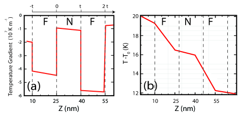
From the FEM, for a heating current of 2 mA through the Pt Joule heaters, a temperature gradient up to 40 K m-1 can be achieved in our devices (see Fig. 6(a)) corresponding to a 8 K across the F/N/F stack (see Fig. 6(b)). The red line in Fig. 6(a) shows the temperature gradient across a Ni80Fe20/Cu/Ni80Fe20 pillar spin valve. From continuity of the heat current at the F/N interfaces, the temperature gradient in the ferromagnetic region is related to that of the N-region as:
| (4) |
where and are the thermal conductivity of the F- and N-region, respectively.
Appendix B Expression for the spin accumulation
To obtain an expression for the spin accumulation , we first need to solve the Valet-Fert 1D-spin diffusion equation for each region in the F/N/F stackSlachter et al. (2010), where is the spin relaxation length. The general solutions for each region reads:
Region I: ()
| (5) |
Region II: ()
| (6) |
Region III: ()
| (7) |
where and denote the spin-up and spin-down, respectively, and are the spin relaxation length in the F- and N-regions.
The spin accumulation at 0 and can then be expressed as a function of these coefficients as = and =, respectively. For a symmetric spin valve the spin accumulation, for example, at interface 0 for the and configurations reads:
| (8) | |||
| (9) |
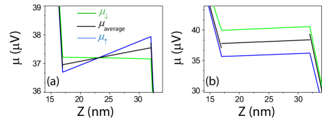
In the limit , Eq. 9 reduces to the result obtained for a single F/N interface given in Ref. Slachter et al., 2010; Scharf et al., 2012. Fig. 7 shows the chemical potential profile across a F/N/F spin valve for the and configurations as obtained from the FEM. At the F/N interfaces, for both and configurations, a discontinuity in the average electrochemical potential leads to an electrochemical potential drop . The spin valve signal is expressed in terms of these electrochemical potential drops as:
| (10) |
Appendix C Material parameters used in 3D-FEM
One important aspect of the finite-element modeling is good knowledge of the temperature and
| Material | |||||
| (nm) | ( S m-1) | (Wm-1K-1) | (VK-1) | (nm) | |
| Ni80Fe20 | 15 | 2.9 | 17 | -18 | 5 |
| Co | 15 | 6.0 | 40 | -22 | 40 |
| Cu | 15 | 15 | 10 | 1.6 | 300 |
| Pt | 40 | 4.2 | 32 | -5 | 5 |
| Pt | 60 | 4.8 | 37 | -5 | 3 |
| Au | 120 | 27 | 180 | 1.7 | 80 |
| AlOx | 8 | 10-18 | 0.12 | 0 | - |
| SiO2 | 300 | 10-19 | 1 | 0 | - |
voltage profiles in the F/N/F pillar devices. This requires usage of appropriate material parameters in the 3D-FEM, which can often lead to underestimating background electrical and thermal voltages if bulk material parameters were used.Slachter et al. (2010); Bakker et al. (2010) Table 2 shows material parameters used in the model. Electrical conductivity of each material was measured using a standard four probe geometry. The thermal conductivity was then calculated using the Wiedemann-Franz law. For device dimensions discussed in the main text, the electronic contribution to the thermal conductivity is dominant over the lattice (phononic) conductivityBakker et al. (2012). The Seebeck coefficients were measured by using the technique presented in Ref. Bakker et al., 2012. One parameter which was not measured but obtained from literature is the spin relaxation length of the ferromagnets. The spin relaxation length for Ni80Fe20 of 5 nm is well established in literature. Dubois et al. (1999); [][andreferencestherein.]bass_spin-diffusion_2007 However, reported spin relaxation length of Co at room temperature vary from 20 nm to 60 nmDubois et al. (1999); Bass and Pratt (2007). The spin valve signals that are extracted from the model depend on the spin relaxation length and the polarization of the conductivity. To tackle the uncertainty in the spin relaxation length in Co, we performed a calculation of the spin signal for varying spin relaxation length values of the ferromagnet. Fig. 8 shows the dependence of the spin signal on the spin relaxation length for different values of the conductivity polarization ranging between 0.42 and 0.47 (for Ni80Fe20) and 0.42 and 0.48 (for Co).
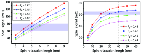
The shaded region in the figures indicates the region in which the measured spin signal values fall. For a choice of spin relaxation lengths of 5 nm (for Ni80Fe20) and 40 nm (for Co), the measured spin valve signals can be well fitted with the model. Hence, we used these two values for the determination of the spin-dependent Seebeck coefficients.
References
- Bauer et al. (2010) G. E. Bauer, A. H. MacDonald, and S. Maekawa, Solid St. Commun. 150, 459 (2010).
- Bauer et al. (2012) G. E. W. Bauer, E. Saitoh, and B. J. van Wees, Nat. Mater. 11, 391 (2012).
- Uchida et al. (2008a) K. Uchida, S. Takahashi, K. Harii, J. Ieda, W. Koshibae, K. Ando, S. Maekawa, and E. Saitoh, Nature 455, 778 (2008a).
- Le Breton et al. (2011) J.-C. Le Breton, S. Sharma, H. Saito, S. Yuasa, and R. Jansen, Nature 475, 82 (2011).
- Walter et al. (2011) M. Walter, J. Walowski, V. Zbarsky, M. Münzenberg, M. Schäfers, D. Ebke, G. Reiss, A. Thomas, P. Peretzki, M. Seibt, J. S. Moodera, M. Czerner, M. Bachmann, and C. Heiliger, Nat. Mater. 10, 742 (2011).
- Slachter et al. (2010) A. Slachter, F. L. Bakker, J.-P. Adam, and B. J. van Wees, Nat. Phys. 6, 879 (2010).
- Flipse et al. (2012) J. Flipse, F. L. Bakker, A. Slachter, F. K. Dejene, and B. J. van Wees, Nat. Nano. 7, 166 (2012).
- Yu et al. (2010) H. Yu, S. Granville, D. P. Yu, and J.-P. Ansermet, Phys. Rev. Lett. 104, 146601 (2010).
- Hatami et al. (2009) M. Hatami, G. E. W. Bauer, Q. Zhang, and P. J. Kelly, Phys. Rev. B 79, 174426 (2009).
- Scharf et al. (2012) B. Scharf, A. Matos-Abiague, I. Zutic, and J. Fabian, Phys. Rev. B 85, 085208 (2012).
- Uchida et al. (2008b) K. Uchida, S. Takahashi, K. Harii, J. Ieda, W. Koshibae, K. Ando, S. Maekawa, and E. Saitoh, Nature 455, 778 (2008b).
- Xiao et al. (2010) J. Xiao, G. E. W. Bauer, K.-c. Uchida, E. Saitoh, and S. Maekawa, Phys. Rev. B 81, 214418 (2010).
- Campbell and Fert (1982) I. Campbell and A. Fert (Elsevier, 1982) pp. 747 – 804.
- Shi et al. (1993) J. Shi, S. Parkin, L. Xing, and M. Salamon, J. Magn. Magn. Mater. 125, L251 (1993).
- Baily et al. (2000) S. A. Baily, M. B. Salamon, and W. Oepts, J. Appl. Phys. 87, 4855 (2000).
- Gravier et al. (2004) L. Gravier, A. Fabian, A. Rudolf, A. Cachin, J.-E. Wegrowe, and J.-P. Ansermet, J. Magn. Magn. Mater. 271, 153 (2004).
- Gravier et al. (2006) L. Gravier, S. Serrano-Guisan, F. Reuse, and J. P. Ansermet, Phys. Rev. B 73, 024419 (2006).
- Cadeville and Roussel (1971) M. C. Cadeville and J. Roussel, J. Phys. F 1, 686 (1971).
- Bakker et al. (2012) F. L. Bakker, J. Flipse, and B. J. van Wees, J. Appl. Phys. 111, 084306 (2012).
- MacDonald (2006) D. MacDonald, Thermoelectricity: An Introduction to the Principles, Dover books on physics (Dover Publications, 2006).
- Slachter et al. (2011a) A. Slachter, F. L. Bakker, and B. J. van Wees, Phys. Rev. B 84, 174408 (2011a).
- Bakker et al. (2010) F. L. Bakker, A. Slachter, J.-P. Adam, and B. J. van Wees, Phys. Rev. Lett. 105, 136601 (2010).
- R. J. Soulen et al. (1999) J. R. J. Soulen, M. S. Osofsky, B. Nadgorny, T. Ambrose, P. Broussard, S. F. Cheng, J. Byers, C. T. Tanaka, J. Nowack, J. S. Moodera, G. Laprade, A. Barry, and M. D. Coey, J. Appl. Phys. 85, 4589 (1999).
- Bass and Pratt (2007) J. Bass and W. P. Pratt, J. of Phys: Condensed Matter 19, 183201 (2007).
- Tsymbal and Zutic (2011) E. Tsymbal and I. Zutic, Handbook of Spin Transport and Magnetism (CRC Press, 2011).
- Tsymbal et al. (1999) E. Y. Tsymbal, D. G. Pettifor, J. Shi, and M. B. Salamon, Phys. Rev. B 59, 8371 (1999).
- Slachter et al. (2011b) A. Slachter, F. L. Bakker, and B. J. van Wees, Phys. Rev. B 84, 020412 (2011b).
- Dubois et al. (1999) S. Dubois, L. Piraux, J. M. George, K. Ounadjela, J. L. Duvail, and A. Fert, Phys. Rev. B 60, 477 (1999).