Magnetic field dependent impact ionization in InSb
Abstract
Carrier generation by impact ionization and subsequent recombination under the influence of magnetic field has been studied for InSb slab. A simple analytic expression for threshold electric field as a function of magnetic field is proposed. Impact ionization is suppressed by magnetic field. However, surface recombination is dependent on the polarity of magnetic field: strengthened in one direction and suppressed on the opposite direction. The former contributes quadratic increase to threshold electric field, and the latter gives additional linear dependence on magnetic field. Based on this study, electrical switching devices driven by magnetic field can be designed.
There are many reports about the impact ionization in semiconductors. However, it is hard to find the one explaining the influence of magnetic field on the impact ionization. To the best of our knowledge it is only recently that a reasonable pilot model has been proposed for the magnetic field effect and compared with experimental results APL-MCT . The previous model is restricted to a special case: electric transport is quasi-ballistic, and carrier recombination is independent of magnetic field. We approach to this issue from more general background, in which an electron can experience many scatterings before reaching the impact ionization, and magnetic field affects carrier recombination process.
Our model gives a result that magnetic field contributes to the carrier generation and recombination process: the field reduces the generation rate and increases the threshold voltage, and it also makes recombination rate sensitive to the polarity of magnetic field. After describing some picture regarding our model qualitatively, quantitative treatment will be followed.
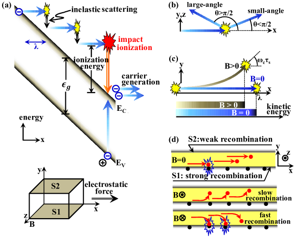
When a high bias voltage is applied, electrons accelerate to a high speed. If the kinetic energy acquired from the electric field equals the ionization energy, impact ionization occurs. Upon impact with the lattice, the electron expends its kinetic energy on ionizing a valence electron (refer Fig. 1 (a)). This process produces electron-hole pairs and abruptly increases the electric current in the device. Impact ionization makes equal number of excess electrons and holes. Because electron mobility is more than 100 times larger than that of hole in InSb, we consider only electronic conduction in impact ionization regime. Before reaching the ionization energy, the energetic electron can experience energy loss due to inelastic scatterings. To achieve impact ionization, the electron should accumulate kinetic energy despite the inelastic scatterings. Magnetic field affects this carrier generation process. When magnetic field is applied, the Lorentz force deflects the electronic trajectory, and the net gain of kinetic energy for a given path length is reduced (Fig. 1 (c)). To achieve the ionization energy a longer trajectory is required; however, this longer trajectory gives rise to the greater possibility of inelastic scattering. Thus, the deflection of the electronic trajectory caused by magnetic field leads to suppression of the impact ionization. To restore impact ionization, a greater electric field is needed to increase the net energy gain between the scatterings. Consequently magnetic field suppresses the carrier generation and increases the threshold electric field.
Recombination is an elimination process of electron-hole pairs and generally follows carrier generation. We are interested in recombination at the two interface, S1 and S2, as depicted in Fig. 1(d). S1 has higher recombination velocity than that of S2 and carrier electrons are readily recombined near S1. Magnetic field produces the Lorentz force. Electrons accumulate or deplete near S1 according to the polarity of magnetic field. When the polarity of magnetic field is negative, negative z-direction in Fig. 1(d), the Lorentz force deflects electrons to S1 and recombination process is facilitated, whereas positive polarity makes electrons near S1 depleted and results in relatively slow recombination.
When the bias voltage exceeds threshold voltage, generation rate is larger than recombination rate, and then number of electrons increases with time, which is known as avalanche state. Under steady-state, however, generation process is balanced with recombination, i.e., generation rate is same as recombination rate. In this work we consider the limit of steady-state, which is on the border of avalanche state.
Now we are in position to treat the model quantitatively. The model proposed in this work presents a simple analytic expression for the threshold electric field as a function of magnetic field. For small band gap semiconductors such as InSb, the ionization energy is approximately equal to the band gap energy Narrow . Energetic electrons undergo inelastic scatterings before their kinetic energies reach . The dominant scattering process of InSb at room temperature is optical phonon scattering Ophonon1 ; Ophonon2 , and the optical phonon energy is known to be 23 meV Ophonon3 . Hence, in the present model each scattering makes an energy loss of . We will obtain a probability for an electron to acquire in spite of energy losses due to inelastic scatterings. Assuming this probability is proportional to carrier generation rate, generation rate will be expressed in terms of electric and magnetic field. Introducing steady-state condition and recombination parameters, a simple analytic relation between the threshold electric field and magnetic field will be proposed.
Adopting Dumke’s theory for InSb Dumke , scatterings are classified into two groups according to scattered directions: small- and large-angle scattering (Fig. 1(b)). For an electron incident along the direction of an electric force, the small-angle scattering produces a scattered angle less than , and the electron is ready to be accelerated again by the electric field after the scattering. The large-angle scattering gives a scattered angle greater than , which results in deceleration and lose a chance to acquire further kinetic energy from the electric field. Thus, large-angle scattering should be avoided to achieve impact ionization.
Our model starts from this classification. The large-angle scattering probability in a time interval of can be given by , where is the relaxation time of the large-angle scattering. Then, the probability of an electron surviving large-angle scattering is for a finite period of time. can be expressed with an electric field. An electric field supplies energy to an electron at a rate of , where is the electron’s unit charge, and is an average velocity parallel to the electrostatic force in the time interval between the successive small-angle scatterings, i.e., , where is the relaxation time of the small-angle scattering. Energy loss by the small-angle scattering is given by . Thus, the net rate of energy gain is expressed by . Using , is rewritten as
| (1) |
A reasonable choice for the lower bound in the integrand is because optical phonon scattering is absent for an electronic energy less than . When an electron with an initial energy of moves to a final energy states of , various paths are possible, and is dependent on these paths. We only consider a path which gives a maximum value of . The path having the shortest electronic path-length gives the maximum . A diffusion effect in the energy space is not considered; it is a second order effect EnergyDiffusion and ignored in this work.
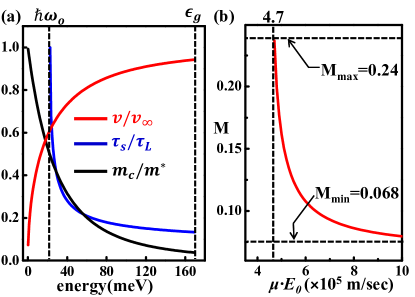
To elucidate in Eq. (1), more details for the small-angle scattering are needed. Velocity is generally dependent on kinetic energy. However, due to the band non-parabolicity Kane of InSb, the velocity of InSb is a slow function of energy for energetic electrons (refer Fig. 2(a)). Hence, the variation of the magnitude of velocity between the successive small-angle scatterings is considered to be negligibly small even though the corresponding energy change is considerable. After a scattering event the electron may have various scattered directions, and these directions work again as incident directions for the next scattering. The shortest path is achieved when this scattered direction is in parallel with the electric force (along x-axis). Thus, the direction of electronic velocity just after the small-angle scattering is considered to be in parallel with the electric force.
Magnetic field is involved with in Eq. (1). In the presence of a magnetic field , classical trajectory of an electron is governed by the Lorentz force. For an electron with velocity of moving toward the electric-force-direction (refer Fig. 1(c)), the classical trajectory gives , where and is electronic effective mass. Using the approximation for low magnetic field, in Eq. (1) can be replaced with . The total scattering rate is nearly independent of energy Turkey , and is favored over in the overall energy range (Fig. 2(a)). Thus, electronic mobility is determined by , which allows . is the effective mass at the conduction band edge. We consider as a small deviation from the threshold electric field at zero magnetic field, . The right term in Eq. (1) can be expanded to the first order of . Following some algebra, it is readily shown that
| (2) |
where
| (3) | |||||
and is amount of at and , i.e., .
The parameters in Eq. (3) can be calculated as follows. An analytic form of is given by Dumke , where and is a wave vector of an electron for a given energy . The non-parabolic dispersion is given by from which the following expressions can be obtained: and . In InSb is 0.17 eV and is 0.013 times the mass of a free electron. Using these relations, and in Eq. (3) can be obtained.
It is only a few electrons which survive large-angle scattering and obtain kinetic energies equal to and finally contribute to the impact ionization Shockley . Because the impact ionization is governed by the energy-gain process specified by , a generation rate per unit carrier due to the impact ionization is assumed to be proportional to . Therefore, in Eq. (2) represents a normalized generation rate.
Recombination relies on magnetic field when the recombination strength at the two interfaces are different (see Fig. 1 (d)). In low magnetic field regime the first order approximation of recombination rate with respect to gives , where is recombination rate at zero field PCexp . When surface recombination is dominant over bulk recombination and sample thickness is smaller than carrier diffusion length, the following simple expression can be obtained from Lile’s resultsLile :
| (4) |
and are surface recombination velocities at the two interfaces, S1 and S2, respectively, and difference of them gives non-zero value of . The steady-state condition asserts that the generation rate is equal to the recombination rate, which leads to and therefore . Then, the threshold field in Eq. (2) is expressed by
| (5) |
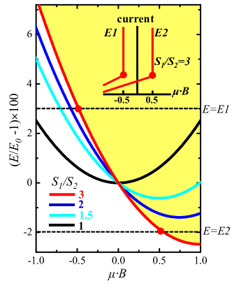
Plotting threshold field according to magnetic field permits an overview of the present model. The plots in Fig. 3 are calculated ones using Eq. (4) and Eq. (5). SI unit for mobility and magnetic field makes dimensionless. For identical surface recombination at the two interface, , the normalized threshold field increases quadratically with magnetic field. This increase is caused by the suppression of impact ionization by magnetic field. Difference in the surface recombination velocities, , adds the linear term and the threshold field becomes asymmetrically dependent on magnetic field. Note that the positive (negative) polarity of magnetic field corresponds to the middle (bottom) diagram in Fig. 1 (d). Weak (strong) recombination results in small (large) threshold electric field.
The curves in Fig. 3 represent boundaries between normal and avalanche states in the space of electric and magnetic field: the avalanche and normal states correspond to the upper and lower areas of the curve, respectively. The yellow area corresponds to avalanche state for , for instance. By varying magnetic or electric field, one of the two conducting state, normal and avalanche state, can be selected. An interesting application of this phenomenon is switching device. For a given electric field, electric current can be changed abruptly by varying magnetic field, which can be a good candidate of magnetic-field-driven electrical switching device (refer the inset of Fig. 3).
References
- (1) J. Lee et al., Appl. Phys. Lett. 97, 253505(2010).
- (2) B.Gelmont, K. Kim and M. Shur, Phys. Rev. Lett. 69, 1280 (1992).
- (3) H. Kishan, S. K. Agarwal and K. D. Chaudhuri, Phys. Rev. B 28, 2078 (1983).
- (4) Y. J. Jung, M. K. Park, S. I. Tae, K. H. Lee, and H. J. Lee, J. Appl. Phys. 69, 3109 (1991).
- (5) N. L. Rowell, D. J. Lockwood, G. Yu, Y. Z. Gao, X. Y. Gong, M. Aoyama and T. Yamaguchi, J. Vac. Sci. Technol. A 22, 935 (2004).
- (6) W. P. Dumke, Phys. Rev. 167, 783 (1968).
- (7) J. P. Leburton and K. Hess, Phys. Rev. B 26, 5623 (1982).
- (8) E. O. Kane, J. Phys. Chem. Solids 1, 249 (1957).
- (9) O. Ozbas and M. Akarsu, Turk. J. Phys. 26, 283 (2002).
- (10) W. Shockley, Solid-State Electron. 2, 35 (1961).
- (11) Using photoconductivity method for n-type InSb at room temperature, we observed that is linear with respect to and . This experimental result will be submitted elsewhere.
- (12) D. Lile, J. Appl. Phys. 41, 3480 (1970).