Spatial and temporal coherence properties of single free-electron laser pulses
A. Singer1, F. Sorgenfrei2, A. P. Mancuso3, N. Gerasimova1, O. M. Yefanov1, J. Gulden1, T. Gorniak4,5, T. Senkbeil4,5, A. Sakdinawat6, Y. Liu7, D. Attwood7, S. Dziarzhytski1, D. D. Mai8, R. Treusch1, E. Weckert1, T. Salditt8, A. Rosenhahn4,5, W. Wurth2∗ and I. A. Vartanyants1,9∗
1 Deutsches Elektronen-Synchrotron DESY, Notkestr. 85, D-22607 Hamburg, Germany
2Institut für Experimentalphysik and CFEL, University of Hamburg, Luruper Chaussee 149, 22761 Hamburg, Germany
3European XFEL GmbH, Albert-Einstein-Ring 19, 22761 Hamburg, Germany
4University of Heidelberg, Im Neuenheimer Feld 253, 69120 Heidelberg, Germany
5Institute of Functional Interfaces, Karlsruhe Institute of Technology, Hermann-von-Helmholtz-Platz 1, 76344 Eggenstein-Leopoldshafen, Germany
6SLAC National Accelerator Laboratory, 2575 Sand Hill Road, Menlo Park, California 94025-7015, USA
7University of California, Berkeley, CA 94720, USA
8Institut für Röntgenphysik, Georg-August-Universität Göttingen, Friedrich-Hund-Platz 1, D-37077 Göttingen, Germany
9National Research Nuclear University, ”MEPhI”, 115409 Moscow, Russia
*Ivan.Vartaniants@desy.de, Wilfried.Wurth@desy.de
Abstract
The experimental characterization of the spatial and temporal coherence properties of the free-electron laser in Hamburg (FLASH) at a wavelength of 8.0 nm is presented. Double pinhole diffraction patterns of single femtosecond pulses focused to a size of about 1010 m2 were measured. A transverse coherence length of m in the horizontal and m in the vertical direction was determined from the most coherent pulses. Using a split and delay unit the coherence time of the pulses produced in the same operation conditions of FLASH was measured to be fs. From our experiment we estimated the degeneracy parameter of the FLASH beam to be on the order of to , which exceeds the values of this parameter at any other source in the same energy range by many orders of magnitude.
OCIS codes: (000.0000) General.
References and links
- [1] W. Ackermann, G. Asova, V. Ayvazyan, A. Azima, N. Baboi, J. Bähr, V. Balandin, B. Beutner, A. Brandt, A. Bolzmann, R. Brinkmann, O. I. Brovko, M. Castellano, P. Castro, L. Catani, E. Chiadroni, S. Choroba, A. Cianchi, J. T. Costello, D. Cubaynes, J. Dardis, W. Decking, H. Delsim-Hashemi, A. Delserieys, G. Di Pirro, M. Dohlus, S. D sterer, A. Eckhardt, H. T. Edwards, B. Faatz, J. Feldhaus, K. Fl ttmann, J. Frisch, L. Fröhlich, T. Garvey, U. Gensch, C. Gerth, M. Görler, N. Golubeva, H. J. Grabosch, M. Grecki, O. Grimm, K. Hacker, U. Hahn, J. H. Han, K. Honkavaara, T. Hott, M. Hüning, Y. Ivanisenko, E. Jaeschke, W. Jalmuzna, T. Jezynski, R. Kammering, V. Katalev, K. Kavanagh, E. T. Kennedy, S. Khodyachykh, K. Klose, V. Kocharyan, M. Körfer, M. Kollewe, W. Koprek, S. Korepanov, D. Kostin, M. Krassilnikov, G. Kube, M. Kuhlmann, C. L. S. Lewis, L. Lilje, T. Limberg, D. Lipka, F. Löhl, H. Luna, M. Luong, M. Martins, M. Meyer, P. Michelato, V. Miltchev, W. D. Möller, L. Monaco, W. F. O. Müller, O. Napieralski, O. Napoly, P. Nicolosi, D. Nölle, T. Nuñez, A. Oppelt, C. Pagani, R. Paparella, N. Pchalek, J. Pedregosa-Gutierrez, B. Petersen, B. Petrosyan, G. Petrosyan, L. Petrosyan, J. Pflüger, E. Plönjes, L. Poletto, K. Pozniak, E. Prat, D. Proch, P. Pucyk, P. Radcliffe, H. Redlin, K. Rehlich, M. Richter, M. Roehrs, J. Roensch, R. Romaniuk, M. Ross, J. Rossbach, V. Rybnikov, M. Sachwitz, E. L. Saldin, W. Sandner, H. Schlarb, B. Schmidt, M. Schmitz, P. Schmüser, J. R. Schneider, E. A. Schneidmiller, S. Schnepp, S. Schreiber, M. Seidel, D. Sertore, A. V. Shabunov, C. Simon, S. Simrock, E. Sombrowski, A. A. Sorokin, P. Spanknebel, R. Spesyvtsev, L. Staykov, B. Steffen, F. Stephan, F. Stulle, H. Thom, K. Tiedtke, M. Tischer, S. Toleikis, R. Treusch, D. Trines, I. Tsakov, E. Vogel, T. Weiland, H. Weise, M. Wellhöfer, M. Wendt, I. Will, A. Winter, K. Wittenburg, W. Wurth, P. Yeates, M. V. Yurkov, I. Zagorodnov, and K. Zapfe, ”Operation of a free-electron laser from the extreme ultraviolet to the water window,” Nat. Photonics 1, 336-342 (2007).
- [2] P. Emma, R. Akre, J. Arthur, R. Bionta, C. Bostedt, J. Bozek, A. Brachmann, P. Bucksbaum, R. Coffee, F. J. Decker, Y. Ding, D. Dowell, S. Edstrom, A. Fisher, J. Frisch, S. Gilevich, J. Hastings, G. Hays, P. Hering, Z. Huang, R. Iverson, H. Loos, M. Messerschmidt, A. Miahnahri, S. Moeller, H. D. Nuhn, G. Pile, D. Ratner, J. Rzepiela, D. Schultz, T. Smith, P. Stefan, H. Tompkins, J. Turner, J. Welch, W. White, J. Wu, G. Yocky, and J. Galayda, ”First lasing and operation of an angstrom-wavelength free-electron laser,” Nat. Photonics 4, 641-647 (2010).
- [3] J. Miao, P. Charalambous, J. Kirz, and D. Sayre, ”Extending the methodology of X-ray crystallography to allow imaging of micrometre-sized non-crystalline specimens,” Nature 400, 342 (1999).
- [4] M. A. Pfeifer, G. J. Williams, I. A. Vartanyants, R. Harder and I. K. Robinson, ”Three-dimensional mapping of a deformation field inside a nanocrystal,” Nature 442, 63 (2006).
- [5] H. N. Chapman, A. Barty, M. J. Bogan, S. Boutet, M. Frank, S. P. Hau-Riege, S. Marchesini, B. W. Woods, S. Bajt, W. H. Benner, R. A. London, E. Plönjes, M. Kuhlmann, R. Treusch, S. Düsterer, T. Tschentscher, J. R. Schneider, E. Spiller, T. Möller, C. Bostedt, M. Hoener, D. A. Shapiro, K. O. Hodgson, D. Van der Spoel, F. Burmeister, M. Bergh, C. Caleman, G. Huldt, M. M. Seibert, F. R. N. C. Maia, R. W. Lee, A. Szöke, N. Timneanu, and J. Hajdu, ”Femtosecond diffractive imaging with a soft-X-ray free-electron laser,” Nat. Phys. 2, 839-843 (2006).
- [6] K. A. Nugent, ”Coherent Methods in the X-ray sciences”, Advances in Physics 59, 1-99 (2010).
- [7] S. Eisebitt, J. Lüning, W. F. Schlotter, M. Lörgen, O. Hellwig, W. Eberhardt, and J. Stöhr, ”Lensless imaging of magnetic nanostructures by X-ray spectro-holography,” Nature 432, 885-888 (2004).
- [8] H. N. Chapman, P. Fromme, A. Barty, T. A. White, R. A. Kirian, A. Aquila, M. S. Hunter, J. Schulz, D. P. DePonte, U. Weierstall, R. B. Doak, F. R. N. C. Maia, A. V. Martin, I. Schlichting, L. Lomb, N. Coppola, R. L. Shoeman, S. W. Epp, R. Hartmann, D. Rolles, A. Rudenko, L. Foucar, N. Kimmel, G. Weidenspointner, P. Holl, M. Liang, M. Barthelmess, C. Caleman, S. Boutet, M. J. Bogan, J. Krzywinski, C. Bostedt, S. Bajt, L. Gumprecht, B. Rudek, B. Erk, C. Schmidt, A. Hömke, C. Reich, D. Pietschner, L. Strüder, G. Hauser, H. Gorke, J. Ullrich, S. Herrmann, G. Schaller, F. Schopper, H. Soltau, K. U. Kühnel, M. Messerschmidt, J. D. Bozek, S. P. Hau-Riege, M. Frank, C. Y. Hampton, R. G. Sierra, D. Starodub, G. J. Williams, J. Hajdu, N. Timneanu, M. M. Seibert, J. Andreasson, A. Rocker, O. Jönsson, M. Svenda, S. Stern, K. Nass, R. Andritschke, C. D. Schröter, F. Krasniqi, M. Bott, K. E. Schmidt, X. Wang, I. Grotjohann, J. M. Holton, T. R. M. Barends, R. Neutze, S. Marchesini, R. Fromme, S. Schorb, D. Rupp, M. Adolph, T. Gorkhover, I. Andersson, H. Hirsemann, G. Potdevin, H. Graafsma, B. Nilsson, and J. C. H. Spence, ”Femtosecond X-ray protein nanocrystallography,” Nature 470, 73-77 (2011).
- [9] M. Seibert, T. Ekeberg, F. R. N. C. Maia, M. Svenda, J. Andreasson, O. Jönsson, D. Odic̀, B. Iwan, A. Rocker, D. Westphal, M. Hantke, D. P. DePonte, A. Barty, J. Schulz, L. Gumprecht, N. Coppola, A. Aquila, M. Liang, T. A. White, A. Martin, C. Caleman, S. Stern, C. Abergel, V. Seltzer, J. Claverie, C. Bostedt, J. D. Bozek, S. Boutet, A. A. Miahnahri, M. Messerschmidt, J. Krzywinski, G. Williams, K. O. Hodgson, M. J. Bogan, C. Y. Hampton, R. G. Sierra, D. Starodub, I. Andersson, S. Bajt, M. Barthelmess, J. C. H. Spence, P. Fromme, U. Weierstall, R. Kirian, M. Hunter, R. B. Doak, S. Marchesini, S. P. Hau-Riege, M. Frank, R. L. Shoeman, L. Lomb, S. W. Epp, R. Hartmann, D. Rolles, A. Rudenko, C. Schmidt, L. Foucar, N. Kimmel, P. Holl, B. Rudek, B. Erk, A. Hömke, C. Reich, D. Pietschner, G. Weidenspointner, L. Strüder, G. Hauser, H. Gorke, J. Ullrich, I. Schlichting, S. Herrmann, G. Schaller, F. Schopper, H. Soltau, K. Kühnel, R. Andritschke, C. Schröter, F. Krasniqi, M. Bott, S. Schorb, D. Rupp, M. Adolph, T. Gorkhover, H. Hirsemann, G. Potdevin, H. Graafsma, B. Nilsson, H. N. Chapman, and J. Hajdu, ”Single mimivirus particles intercepted and imaged with an X-ray laser,” Nature 470, 78-81 (2011).
- [10] A. P. Mancuso, O. M. Yefanov, I. A. Vartanyants, ”Coherent diffractive imaging of biological samples at synchrotron and free electron laser facilities,” J. of Biotechnology, 149, 229 (2010).
- [11] I. A. Vartanyants, I. K. Robinson, I. McNulty, C. David, P. Wochner, and T. Tschentscher, ”Coherent X-ray scattering and lensless imaging at the European XFEL Facility,” J. Synchrotron Radiat. 14, 453-470 (2007).
- [12] L. Young, E. P. Kanter, B. Krässig, Y. Li, A. M. March, S. T. Pratt, R. Santra, S. H. Southworth, N. Rohringer, L. F. Dimauro, G. Doumy, C. A. Roedig, N. Berrah, L. Fang, M. Hoener, P. H. Bucksbaum, J. P. Cryan, S. Ghimire, J. M. Glownia, D. A. Reis, J. D. Bozek, C. Bostedt, and M. Messerschmidt, ”Femtosecond electronic response of atoms to ultra-intense X-rays,” Nature 466, 56-61 (2010).
- [13] L. W. Whitehead, G. J. Williams, H. M. Quiney, D. J. Vine, R. A. Dilanian, S. Flewett, K. A. Nugent, A. G. Peele, E. Balaur, and I. McNulty, ”Diffractive imaging using partially coherent x rays,” Phys. Rev. Lett. 103, 243902 (2009).
- [14] B. Abbey, L. W. Whitehead, H. M. Quiney, D. J. Vine, G. A. Cadenazzi, C. A. Henderson, K. A. Nugent, E. Balaur, C. T. Putkunz, A. G. Peele, G. J. Williams, and I. McNulty, ”Lensless imaging using broadband X-ray sources,” Nat. Photonics 5, 420 (2011).
- [15] Y. H. Jiang, T. Pfeifer, A. Rudenko, O. Herrwerth, L. Foucar, M. Kurka, K. U. Kühnel, M. Lezius, M. F. Kling, X. Liu, K. Ueda, S. Düsterer, R. Treusch, C. D. Schröter, R. Moshammer, and J. Ullrich, ”Temporal coherence effects in multiple ionization of N2 via XUV pump-probe autocorrelation,” Phys. Rev. A 82, 041403 (2010).
- [16] http://hasylab.desy.de/facilities/flash/publications/selected_publications/index_eng.html
- [17] A. A. Sorokin, S. V. Bobashev, T. Feigl, K. Tiedtke, H. Wabnitz, and M. Richter, ”Photoelectric effect at ultrahigh intensities,” Phys. Rev. Lett. 99, 213002 (2007).
- [18] K. Honkavaara, B. Faatz, J. Feldhaus, S. Schreiber, R.Treusch, J.Rossbach, ”FLASH UPGRADE”, First International Particle Accelerator Conference, IPAC’10, Kyoto, Japan, (2010).
- [19] A. Singer, I. A. Vartanyants, M. Kuhlmann, S. Düsterer, R. Treusch, and J. Feldhaus, ”Transverse-coherence properties of the free-electron-laser FLASH at DESY,” Phys. Rev. Lett. 101, 254801 (2008).
- [20] I. A. Vartanyants, A. P. Mancuso, A. Singer, O. M. Yefanov, and J. Gulden, ”Coherence measurements and coherent diffractive imaging at FLASH,” J. Phys. B 43, 194016 (2010).
- [21] S. Roling, B. Siemer, M. Wöstmann, H. Zacharias, R. Mitzner, A. Singer, K. Tiedtke, and I. A. Vartanyants, ”Temporal and spatial coherence properties of free-electron-laser pulses in the extreme ultraviolet regime,” Phys. Rev. ST Accel. Beams 14, 080701 (2011).
- [22] E. L. Saldin, E. A. Schneidmiller and M. V. Yurkov, The Physics of Free Electron Lasers, (Springer, 2010).
- [23] I. A. Vartanyants, A. Singer, A. P. Mancuso, , O. M. Yefanov, A. Sakdinawat, Y. Liu, E. Bang, G. J. Williams, G. Cadenazzi, B. Abbey, H. Sinn, D. Attwood, K. A. Nugent, E. Weckert, T. Wang, D. Zhu, B. Wu, C. Graves, A. Scherz, J. J. Turner, W. F. Schlotter, M. Messerschmidt, J. Lüning, Y. Acremann, P. Heimann, D. C. Mancini, V. Joshi, J. Krzywinski, R. Soufli, M. Fernandez-Perea, S. Hau-Riege, A. G. Peele, Y. Feng, O. Krupin, S. Moeller, and W. Wurth, ”Coherence Properties of Individual Femtosecond Pulses of an X-Ray Free-Electron Laser,” Phys. Rev. Lett. 107, 144801 (2011).
- [24] J. W. Goodman, Statistical Optics (Wiley, New York, 2000).
- [25] L. Mandel and E. Wolf, Optical Coherence and Quantum Optics (Cambridge University Press, 1995).
- [26] W. F. Schlotter, F. Sorgenfrei, T. Beeck, M. Beye, S. Gieschen, H. Meyer, M. Nagasono, A. Föhlisch, and W. Wurth, ”Longitudinal coherence measurements of an extreme-ultraviolet free-electron laser”, Optics Letters 35, 372-374 (2010).
- [27] F. Sorgenfrei, W. F. Schlotter, T. Beeck, M. Nagasono, S. Gieschen, H. Meyer, A. Föhlisch, M. Beye, and W. Wurth, ”The extreme ultraviolet split and femtosecond delay unit at the plane grating monochromator beamline PG2 at FLASH”, Rev. Sci Instr. 81, 043107 (2010).
- [28] R. Mitzner, B. Siemer, M. Neeb, T. Noll, F. Siewert, S. Roling, M. Rutkowski, A. A. Sorokin, M. Richter, P. Juranic, K. Tiedtke, J. Feldhaus, W. Eberhardt, and H. Zacharias, ”Spatio-temporal coherence of free electron laser pulses in the soft x-ray regime”, Optics Express 16, 19909-19919 (2009).
- [29] E. L. Saldin, E. A. Schneidmiller, and M. V. Yurkov, ”Coherence properties of the radiation from X-ray free electron laser”, Opt. Communications 281, 1179-1188 (2008).
- [30] I. A. Vartanyants and A. Singer, “Coherence properties of hard x-ray synchrotron sources and x-ray free-electron lasers,” New J. Phys. 12, 035004 (2010).
- [31] R. A. Bartels, A. Paul, H. Green, H. C. Kapteyn, M. M. Murnane, S. Backus, I. P. Christov, Y. Liu, D. Attwood, and C. Jacobsen, ”Generation of Spatially Coherent Light at Extreme Ultraviolet Wavelengths,” Science, 297, 376-378 (2002).
- [32] B. W. J. McNeil and N. R. Thompson, ” X-ray free-electron lasers”, Nat. Photon., 12, 814-821, (2010).
- [33] F. Staier, ”Entwicklung, Bau und Test einer UHV Röntgenstreukammer für die digitale In-Line Holographie,” PhD Thesis (University of Heidelberg, 2009).
- [34] M. Wellhöfer, M. Martins, W. Wurth, A. Sorokin, and M. Richter, ”Performance of the monochromator beamline at FLASH,” J. Opt. A, Pure Appl. Opt. 9, 749-756 (2007).
- [35] The assumptions used in deriving equation (4) were well satisfied in our experimental geometry. The maximum time delay introduced through the path length difference was fs and was smaller than the temporal coherence length fs measured by the split and delay unit (see below). Therefore, we could safely assume that in transverse coherence measurements and .
- [36] An unconstrained fit yields a value of in both directions and provides slightly larger values for the transverse coherence length. We attribute this to inhomogenities in the transmission through the pinholes.
- [37] J. Chalupsky, J. Krzywinski, L. Juha, V. Hajkova, J. Cihelka, T. Burian, L. Vyain, J. Gaudin, A. Gleeson, M. Jurek, A. R. Khorsand, D. Klinger, H. Wabnitz, R. Sobierajski, M. Störmer, K. Tiedtke, and S. Toleikis, ”Spot size characterization of focused non-Gaussian X-ray laser beams”, Opt. Express 18, 27836 (2010).
- [38] We attribute this positional uncertainty to both, instabilities of the sample stages and beam positional jitter.
- [39] In our experiment the maximum of did not reach unity but rather a value of . The reason for this is that the full beam was split in the middle and overlapped again meaning that parts of the center of the beam were overlapped with parts of the edge of the beam (see [27] for details). This corresponds to a large pinhole separation in a Young’s double pinhole experiment yielding reduced values of . The beam was not spatially filtered with the apertures of the PG2 beamline, which would increase the contrast. Additionally, Ce:YAG crystals are known to saturate at high intensities [40], which can result in a degradation of fringe visibility.
- [40] D.P. Bernstein, Y. Acremann, A. Scherz, M. Burkhardt, J. St hr, M. Beye, W. F. Schlotter, T. Beeck, F. Sorgenfrei, A. Pietzsch, W. Wurth, A. F¨hlisch, ”Near edge x-ray absorption fine structure spectroscopy with x-ray free-electron lasers,” Appl. Phys. Lett. 95, 134102 (2009).
- [41] We used the following FLASH operation parameters [42, 43] , mm, A, , m, and to calculate the FEL parameter in equation (11). The error is derived by applying the Gaussian error propagation law.
- [42] http://flash.desy.de/accelerator/, access December 2011.
- [43] B. Faatz, private communication.
1 Introduction
Free-electron lasers (FELs) based on the self-amplified spontaneous emission (SASE) principle produce extremely brilliant, highly coherent radiation in the extreme ultraviolet (XUV) [1] and hard x-ray [2] range. Utilizing the high photon flux, the femtosecond pulse duration and the high degree of coherence, techniques like coherent x-ray diffraction imaging (CXDI) [3, 4, 5, 6] x-ray holography [7] and, recently, nano-crystallography [8] promise important new insights in biology [9, 10], condensed matter physics [11] and atomic physics [12]. Some of these methods can be implemented only if the radiation is sufficiently coherent, both spatially and temporally. This means that the knowledge of the coherence is mandatory for the success of these experiments. Moreover, it was shown recently that small deviations from perfect coherence can be taken into account in the CXDI method if the degree of coherence is known [13, 14]. Both, temporal and transverse coherence effects also play a role in the now accessible field of non-linear excitations of atoms and molecules [15].
Free-electron laser in Hamburg (FLASH) started its operation in 2005 as the first FEL in the XUV wavelength range. It delivered radiation of unprecedented brightness at a wavelength down to 6.5 nm (first reached in October 2007) and generated pulses as short as 10-15 fs Full Width at Half Maximum (FWHM) [1]. A variety of ground breaking experiments [16], including the first demonstration of single pulse femtosecond coherent imaging [5] and studies of the photoelectric effect at ultra-high intensities [17], were performed at FLASH. In 2009 FLASH went through a major upgrade [18], where, along with another electron energy upgrade yielding photon wavelengths down to about 4 nm, a 3rd harmonic accelerator module was installed, in order to improve the capabilities for longitudinal electron bunch compression and in this way enhance the machine stability. This led to a higher stability of the FEL operation at the expense of longer pulse durations, typically around 100 fs. The aim of our experiment was to characterize the coherence properties of the FLASH beam after this upgrade.
Measurements of transverse coherence properties of FEL sources have been reported earlier [19, 20, 21]. In these experiments a number of shots were averaged and an average transverse coherence length was determined. Contrary to a visible laser, where a resonator typically permits the growth of only a single transverse ”TEM00” mode, in a SASE FEL a variety of modes can be amplified [22]. The signal at the end of the undulator depends on the shot noise in the electron bunch entering the undulator. As such, the radiation properties, including the transverse coherence, may change from shot to shot. Although no significant shot to shot variations of the coherence properties were observed at the Linac Coherent Light Source (LCLS) [23], at FLASH, with its lower electron and photon energies, we may expect these variations to be more important. In this paper we present measurements of the transverse coherence properties of FLASH and investigate how they fluctuate from shot to shot. To address this important question, we employed the single-shot methodology developed in [23] and conducted Young’s double pinhole experiment [24, 25] with single FEL pulses.
The other important statistical characteristic of the FEL radiation is its temporal coherence. Due to the same electron bunch instabilities, which lead to partial spatial coherence, the FEL pulses are partially coherent in the time domain. The photon pulse is not merely a single longitudinal mode but rather consists of several spikes with a width of about the coherence time. These longitudinal modes can be correlated and interfere with each other, which affects the coherence time. This complicated phenomena was recently observed experimentally [26]. To analyze the temporal coherence properties at FLASH we used an autocorrelation setup [27]. The single FLASH pulse was split into two parts on a wavefront dividing split mirror. These two parts were brought to an overlap on the detector with an adjustable time delay. The visibility of the interference fringes in the overlap region contains information on the degree of correlation of the time delayed pulses, and therefore on the temporal coherence properties of the radiation.
A number of measurements of the transverse [19, 20, 21] and temporal [21, 28, 26] coherence of FLASH operating before the upgrade have been reported. Here we combine spatial and temporal coherence measurements using Young’s double pinholes and a split and delay unit at the same operation conditions of FLASH after its upgrade in 2009.
2 Theory
The concept of optical coherence is associated with interference phenomena, where the Mutual Coherence Function (MCF) [24, 25]
| (1) |
plays the major role. It describes the correlation between two complex values of the electric field and at different points and in space, separated by the time interval . The brackets denote the time average over a time interval .
To experimentally characterize the MCF, the spatial and temporal properties are measured. The former can be accessed by Young’s double pinhole experiment [24, 25], whereas the latter may be studied using a split and delay line [26, 28]. In these interference experiments the complex field is divided into two parts, and , by the double pinhole or the split mirror. Here and are the positions in the plane of the apertures or the split mirror. The interference between the two propagated fields and is observed in the overlap region on the detector and the degree of coherence of the incident radiation field can be determined from the contrast of the interference fringes. The coordinate lies in the observation plane and is the time delay, which is introduced through the difference between the propagation path lengths of the two beams. For narrowband light with an average wavelength the intensity distribution measured in the observation plane may be expressed as [24]
| (2) |
where are the intensities of the individual fields and
| (3) |
is the complex degree of coherence in the plane of the apertures or the split mirror. Here, according to the definition (1) , are the intensities incident on the double pinhole or on the split mirror. In equation (2) is the rapidly changing phase of , which gives rise to interference fringes in the observation plane. The slowly varying phase of is denoted by .
In a Young’s double pinhole experiment the fast varying phase term can be expressed as [24] . Here is the double pinhole to detector distance, and is the pinhole separation in the horizontal and vertical direction. The intensities in equation (2) are given by , where is the Airy diffraction pattern from a round pinhole of diameter [24]. The incident intensity is assumed to be constant across each pinhole. For sufficiently big pinhole to detector distances the Airy patterns from different pinholes overlap on the detector [24] and equation (2) can be simplified to
| (4) |
where the effective complex degree of coherence is given by
| (5) |
From the definition of in equation (5) it is immediately seen that if the intensities incident on individual pinholes differ in magnitude, the contrast observed in the experiment is reduced as compared with the degree of coherence of the incident radiation. If the time delay associated with the path length difference between the pinhole one and two is smaller than the coherence time , then and are good approximations. Typically, the double pinhole experiment is conducted for different pinhole separations and the transverse coherence length is defined as a characteristic width of . To characterize the transverse coherence it is convenient to introduce the normalized degree of coherence as [29, 30]
| (6) |
This quantity approaches unity for highly coherent and zero for incoherent radiation.
In the split and delay line the interfering fields are generated at the split mirror and are propagated through different arms of the instrument. Both beams are brought to full overlap in the observation plane with approximately equal intensities . The interference fringes occur due to the recombination angle , which also is the angle between the wavefronts of both beams. The fast varying phase term in equation (2) in this case is given by [21] , where is the unit vector along the direction perpendicular to the interference fringes. The analysis of the visibility of fringes can be conveniently performed using the Fourier transform. Assuming that the modulus of the complex coherence function and are constant within the interference pattern, the Fourier transform of equation (2) yields [31]
| (7) |
where and denote the Fourier transforms of and , is the Dirac delta function, is the convolution operator, is the frequency coordinate, and the fringe frequency is given by . Equation (7) contains one central term and two ’sideband’ terms. The central term is the sum of the autocorrelation functions of the two beams. The ’sideband’ terms contain the information on the degree of cross correlation between the interfering fields. According to equation (7) the modulus of the complex coherence function can be determined as
| (8) |
For a fixed overlap the visibility of the resulting fringes is analyzed as a function of the time delay caused by the two different propagation distances in the split and delay unit. From these measurements one can deduce the coherence time of the radiation, , which we defined according to [24] as
| (9) |
where
| (10) |
In FEL theory the coherence time can be approximated by [22, 32]
| (11) |
where is the resonance frequency, is the FEL parameter and is the speed of light. The FEL parameter in equation (11) can be expressed as , where is the electron beam current, is the undulator parameter, is the undulator period, is the Alfvén current, is the relativistic (Lorentz) factor, and is the transverse Root Mean Square (rms) size of the electron bunch. The coupling factor for a planar undulator is , where and are Bessel functions of the first kind and .
3 Experiment
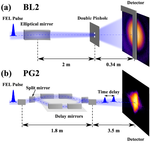
The transverse and temporal coherence of FLASH were measured at a lasing wavelength of 8.0 nm. The FEL generated single pulses at a repetition rate of 10 Hz with an average energy of 180 J per pulse. FLASH was operated with a bunch charge of 0.8 nC and an electron energy of around 891 MeV. Six modules of the undulator with a total length of 30 m were used. The FEL was expected to lase in the saturation regime at these operation conditions. The pulse duration was estimated to be about 100 fs (see below). The outline of both experiments for the measurements of the transverse and longitudinal coherence is shown in Figure 1.
(a) Transverse coherence measurements
The spatial coherence measurements were carried out at the BL2 beamline at FLASH (see Figure 1(a)). The beam delivery system consisted of two flat distribution mirrors and an elliptical mirror, which focused the beam to a size of about (FWHM) 70 m downstream from the undulator exit. The acceptance of the mirrors was sufficiently large in both directions, therefore we assume that the beam was not cut by the mirrors. The double pinhole apertures were positioned in the focus inside a dedicated vacuum chamber (HORST [33]). Double pinholes with varying separations between the pinholes have been manufactured to measure the degree of coherence at different relative distances. The pinhole separation varied between 4 m and 11 m in the horizontal direction and between 2 m and 15 m in the vertical direction. With increasing pinhole separation less intense parts of the beam were probed. To record a similar signal from all apertures we varied the pinhole diameter between 340 nm for the smallest pinhole separation and 500 nm for the largest pinhole separation.
Due to the extremely high power densities in the focus, each aperture set was destroyed during the interaction with a single FEL pulse. About ten identical apertures were manufactured for each pinhole separation to improve statistics of the measurements. All apertures were fabricated by electroplating a 1.3 m thick gold layer on top of a 100 nm silicon nitride substrate. The substrate was supported by 5050 windows etched in a 200 m thick silicon wafer and was eventually removed by hydrofluoric acid to increase the transmission through the pinholes. Individual pairs of apertures were separated by 768 m from each other in both directions.
The double pinhole diffraction patterns were recorded with an in-vacuum Charge Coupled Device (CCD) (LOT/Andor DODX436-BN) with pixels, each m in size. A 3 mm linear beamstop manufactured out of B4C was oriented perpendicular to the interference fringes and protected the CCD from the direct FEL beam (see Figure 1(a)). A 200 nm thick Pd foil supported by 100 nm parylene-N was mounted mm upstream from the camera to absorb the visible light generated during the damage process of the apertures. A sample to detector distance of 0.34 m provided a sufficient sampling of the fringes (13 pixels per fringe for a 15 m pinhole separation), which is necessary for the evaluation of the double pinhole interference patterns.
(b) Temporal coherence measurements
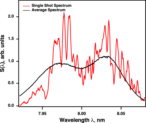
The temporal coherence measurements were carried out directly after the transverse coherence measurements at the plane grating monochromator beamline PG2 [34]. There was no further tuning of the machine involved. A typical single pulse and average spectra are shown in Figure 2. From the average spectrum we estimate a FWHM bandwidth of about 1.4% for the FEL radiation. Analyzing individual single shot spectra we estimate an average pulse duration to be on the order of fs. This number is retrieved by counting the individual spikes in the single shot spectra and multiplying the average number of spikes per pulse with the measured coherence time (see below).
The plane grating monochromator was used in zero order, and the longitudinal coherence was measured by using the permanently installed split and delay unit [27] (see Figure 1(b)) of the PG2 beamline. This device is able to geometrically split each pulse delivered by FLASH into two pulses and delay them up to 5.1 ps in time with respect to each other with less than 100 as accuracy. Afterwards, the two pulses can be overlapped in space on a Ce:YAG screen 3.5 m downstream in the beamline creating interference fringes when the pulses overlap in time. The images of the overlapped pulses were recorded at the machine pulse repetition rate of 10 Hz using a Basler scA1300-32fm FireWire CCD camera outside of the vacuum chamber. The camera has in total pixels with a pixel size of m. As optics we used a Sill Optics S5LPJ0635 lens with a magnification of yielding sufficient resolution to resolve the interference fringes. The complete setup was mounted on an x-y positioning stage allowing for a fast alignment of the camera to the beam position. The measurements were not done in the focus of the beam but rather between the two intermediate foci for the horizontal and the vertical direction.
4 Results
(a) Transverse coherence measurements
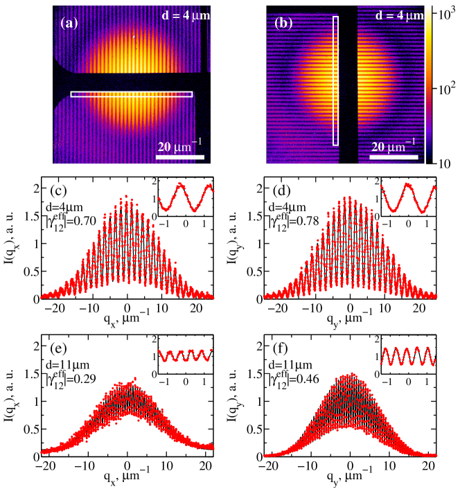
Typical recorded and dark field corrected single shot diffraction patterns are shown in Figure 3(a,b) as a function of the momentum transfer for a pinhole separation of 4 m. In Figure 3(a) the double pinhole was oriented horizontally and the vertical fringes originate from the interference between the field scattered at different pinholes. In Figure 3(b) a similar diffraction pattern measured with a vertically oriented double pinhole is presented. The first minimum of the Airy distribution is visible at m-1 in both figures. The line scans through the measured diffraction patterns (Figure 3(c,d)) show a high contrast level for the small pinhole separation for both, the horizontal and vertical directions. The contrast decreases for larger separations (see Figure 3(e,f)), which indicates a smaller magnitude of the complex degree of coherence at these length scales.
On most of the diffraction patterns additional noise was observed. It consisted of a constant background and a few hot pixels randomly distributed over the whole diffraction pattern (’salt and pepper noise’). We attribute the appearance of this noise to the light generated during the damage process of the pinholes. Since the Pd foil was not attached to the detector but was positioned a few centimeters upstream, light could leak between the foil and detector and can be a source of this noise.
To determine the modulus of the effective complex degree of coherence for each measured single shot interference pattern, equation (4) was fit to the data [35]. We added a constant to equation (4) to accommodate for the presence of the constant background noise. The hot pixels were removed from the diffraction patterns and were not considered in the analysis procedure. In particular, the two-dimensional area marked with a white rectangle in Figure 3(a,b) was analyzed. Eight fit parameters including , , , , , and the position of the optical axis in the horizontal and vertical directions were found. The quality of fit was characterized by an -factor , where is the background corrected measured data, is the fit and summation is made over all points in the fitted area. All fits with were excluded from the further analysis (less than 50% from the total number of the diffraction patterns in each direction). For each shot a confidence interval of was determined as a value for which was twice as large as the minimum value, while all other fit parameters were fixed. Typical fit results are shown in Figure 3(c-f).
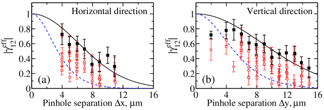
As a result of the data analysis, the modulus of the effective complex degree of coherence as a function of the pinhole separation is shown in Figure 4(a,b) for the horizontal and vertical directions. We approximated the highest values of for each pinhole separation (shown by black squares) with the Gaussian function shown by black line in Figure 4(a,b). This yields an upper bound estimate of the transverse coherence length in each direction. In this way we determined the transverse coherence length (rms) to be m in the horizontal and m in the vertical direction. During this fitting procedure we fixed the value of at zero pinhole separation to one according to its definition (1,3,5) [36].
According to equation (3) the information about the intensity profile of the beam is required to characterize the MCF completely. To measure the beam profile in the plane of the apertures we analyzed PMMA imprints produced by single FEL pulses with a varying degree of attenuation of the beam [37]. Three sets of PMMA imprints with one order of magnitude difference in attenuation of the incoming beam were analyzed. Using the Gaussian beam approximation a beam size of m2 FWHM was determined. In the horizontal direction additional features on the sides of the beam were observed. For the strongly attenuated beam, however, round craters, m in diameter, indicate that the central part of the beam is round.
As follows from our analysis (see Figure 4) the values of vary significantly from shot to shot for the same pinhole separation. We attribute this variation mainly to the beam position instabilities in the plane of the sample. If the center of the beam does not hit the center of the double pinhole the intensities incident on individual pinholes will necessarily be different. This difference yields a reduced value of as compared with (see equation (5)). We estimated the deviation of the beam center relative to the sample by analysing the PMMA imprints measurements. The positions of thirty two craters in the PMMA were found and compared with the nominal positions expected from the stage movement. A maximum offset between the position of the apertures and the incident beam was determined to be m in the horizontal and m in the vertical direction [38]. Using these values as the offset of a Gaussian beam with a size of , we can calculate the difference of the intensity incident on pinhole one and two. The error imposed by this uncertainty in position compared to the Gaussian fit through the highest values of (black solid line in Figure 4(a,b)) is shown by the blue dashed line in Figure 4(a,b). Most of the measured values lie between the black and the blue line, which indicates that the positional uncertainty is the dominant cause for the apparent variations in . However, as this error is quite significant, we cannot definitively exclude shot to shot variations in the degree of coherence .
Combining the measured beam size with the highest values of the complex coherence function we determined the degree of transverse coherence (see equation (6)) of the radiation at FLASH. Utilizing the Gaussian Schell-model [25] we estimated a value of in the horizontal and in the vertical directions. That gives for the total degree of coherence obtained in our experiment a value of . The decomposition of the radiation field into a sum of coherent modes [25, 30] has shown that 2 modes in each direction are sufficient to describe the coherence properties in the measured area of the beam. This means (see for derivation [23]) that about % of the total radiation power is concentrated in the dominant transverse mode.
The coherence measurements presented here indicate a significantly higher degree of transverse coherence of the FLASH beam than previously reported values [19]. We attribute this to the implementation of the 3rd harmonic cavity to the FLASH accelerator complex [18]. A comparison with values reported for the LCLS [23] shows, that both machines, though operating at significantly different wavelengths and different pulse energies, provide similar values of the degree of coherence (in the measurements at LCLS [23] the wavelength was 1.6 nm, the average energy per pulse 1 mJ and the degree of coherence about 75%).
(b) Temporal coherence measurements
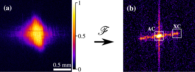
The visibility of the interference pattern was measured as a function of the time delay between the two pulses. From these measurements one can deduce the mean electric field autocorrelation function of the FEL radiation. The analysis of the data was done by performing a two-dimensional Fourier transform of the recorded fringe patterns (see equation (7) and reference [26] for details). In comparison with the experiment reported in [26] the detector unit has been significantly improved by isolation of the detection system from the background light (light from the experimental hall) and magnification of the FEL beam size on the detector. Since FLASH was operating in single bunch mode, each image contains the interference pattern of a single pulse on the Ce:YAG crystal. Therefore, the presented data was not affected by blurring of the interference patterns and thus reduction of the contrast. This blurring can appear for long delays when microbunches in a bunch train have a slightly different wavelength which leads to a change of the fringe spacing [26].
A typical single shot interferogram for the time delay is shown in Figure 5(a). From the recorded interference patterns we subtracted the background, which was calculated for each image by averaging a region in the corner of the image. After this background subtraction the occasionally occurring negative values were set to zero. A two dimensional Fourier transform (see Figure 5(b)) of the processed image was calculated and also background corrected. The modulus of the complex coherence function was found for each single shot according to equation (8). An average of the Fourier transform of the data in the regions marked by AC (autocorrelation) and XC (cross correlation) (see Figure 5(b)) were used in this analysis. A number of single shot measurements for each time delay was averaged to improve the statistics and to determine the average complex coherence function as a function of the time delay [39].
| Peak # | FWHM (fs) | FWHM |
|---|---|---|
| Peak 1 | ||
| Peak 2 | ||
| Peak 3 |
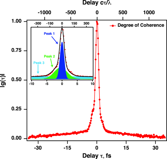
In order to determine the coherence time the modulus of the complex coherence function was normalized according to equation (10). Figure 6 shows the normalized value as a function of the time delay. The measured coherence time determined by equation (9) has a value of fs, which corresponds to about wavecycles (). For the FLASH parameters used in our experiment [41] we estimated the FEL parameter to be . That gave theoretical estimate of the coherence time using equation (11) fs, that concords well with the measured coherence time.
Close inspection of Figure 6 shows, that the modulus of the complex coherence function contains several time scales, which has been also reported in [26]. To determine these time scales the data were fitted with three Gaussian functions. The result of this fit is presented in Table 1. We interprete these three contributions in the following way. The shortest peak 1 with a width of fs ( wavecycles) is the contribution of the coherence time of the single FEL spikes within one pulse. The longest peak 3 with a width of fs ( wavecycles) describes the decay of the degree of correlation between individual spikes in the FEL pulse. In our experiment, the normalized temporal coherence reaches a value close to zero for delays of about wavecycles, whereas the measurement of the temporal coherence reported in [26] at 9.6 nm has reached zero already at about wavecycles. In this experiment, the electron bunch charge was set to 0.76 nC, which is close to the 0.8 nC, used during our measurements. However, before the upgrade, FLASH was operated with a non symmetrical electron bunch shape yielding a leading high current peak and a long tail [18]. After the implementation of the 3rd harmonic cavity the pulses tend to be longer. Short pulses were not accessible during our measurements immediately following the restart of the FLASH after the upgrade.
The asymmetry, which can be seen in Figure 6 for short delays ( fs) can be attributed to an asymmetry in the two photon beams and is governed by peak 2 with a width of fs ( wavecycles). It may be a result of a non-constant non-linear chirp in the transverse direction of the photon beam, as well as a tilt of the wave front or longitudinal pulse double structures. Since we split the incoming beam by means of wavefront division, this can be back-translated to a non-linear chirp along the transverse direction of the photon beam. These asymmetries have also been measured in several other experiments using different techniques [26, 28, 15].
5 Discussion
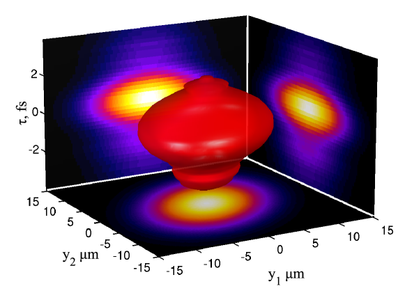
The statistical properties of the radiation at FLASH are described by the full mutual coherence function . We have characterized the MCF as a function of the space coordinates and as a function of the time delay. Combining the results from these measurements we determined the magnitude of the complete MCF of the radiation at FLASH, assuming the radiation is cross spectrally pure [24]. According to its definition (1) the MCF is a function of two coordinates in space and one coordinate in time. For visualization purposes we show a 3D representation of the MCF in the vertical direction in Figure 7. A similar result is obtained for the MCF in the horizontal direction.
Taking into account the pulse duration we can estimate the degeneracy parameter [25, 22] of the FLASH beam. It describes the number of photons found in the same quantum state or a single mode of radiation. The average total number of photons per single pulse was about . From our transverse coherence measurements we have approximated that about 65% of the total power is concentrated in the dominant transverse mode. Using the determined coherence time of about 2 fs and the average pulse duration of 100 fs we estimate that about 1% of the total power is concentrated in a single longitudinal and transverse mode. This yields an estimate of the degeneracy parameter to . This number is significantly higher than at any other source at these photon energies. For instance at synchrotron sources the degeneracy parameter is typically . The measured degeneracy parameter of FLASH concords well with the theoretical predictions [22] based on detailed SASE simulations. It is also similar to the degeneracy parameter of optical light lasers [25]. This high value of the degeneracy could lead to new applications of FEL sources in the field of quantum and non-linear optics in the XUV and x-ray regime.
6 Conclusions
We have experimentally characterized the transverse and longitudinal coherence properties of the XUV free-electron laser FLASH. Young’s double pinhole experiment was conducted to find the transverse coherence length of the focused FEL beam. The transverse coherence length of the focused FLASH beam was determined to be m in the horizontal and m in the vertical direction. Additionally, the intensity beam profile was measured to be m2. From our measurements we conclude that the focused FLASH beam is highly coherent with a total degree of transverse coherence of about 40%. A mode decomposition has shown that about 60% of the total power is concentrated in the fundamental mode. These high values indicate that almost the full transverse photon flux is coherent and can be used for coherence-based applications.
The temporal coherence was measured to be fs, which is in good agreement with the expected theoretical value of fs. While the main coherence peak fits well with the previous measurements, the broad component is about a factor of four larger. We attribute this effect to the longer pulses after the implementation of the 3rd harmonic cavity.
We have also estimated the degeneracy parameter of FLASH radiation to be in the range of to . This number is significantly larger than at any other existing sources operating at this photon energy range and is comparable with the degeneracy parameter of conventional optical lasers.
7 Acknowledgements
We acknowledge the help of K. Hagemann in post processing the double pinhole samples for Young’s experiments and B. Faatz for his assistance in the theoretical estimates of the FEL properties. Part of this work was supported by BMBF Proposal 05K10CHG ”Coherent Diffraction Imaging and Scattering of Ultrashort Coherent Pulses with Matter” in the framework of the German-Russian collaboration ”Development and Use of Accelerator-Based Photon Sources”. We acknowledge the BMBF funding through the Virtual Institute VH-VI-403 from the Helmholtz society. The KIT/Heidelberg group and the University of Hamburg acknowledges funding from BMBF (05K10VH4 and 05K10GU3, respectively within FSP 301 FLASH).