A hybrid soliton-based system: generation and steering of cavity solitons by means of photorefractive soliton electro-activation
Abstract
We propose a hybrid soliton-based system consisting of a centrosymmetric photorefractive crystal, supporting photorefractive solitons, coupled to a vertical cavity surface emitting laser, supporting multistable cavity solitons. The composite nature of the system, which couples a propagative/conservative field dynamics to a stationary/dissipative one, allows to observe a more general and unified system phenomenology and to conceive novel photonic functionalities. The potential of the proposed hybrid system becomes clear when investigating the generation and control of cavity solitons by propagating a plane wave through electro-activated solitonic waveguides in the crystal. By changing the electro-activation voltage of the crystal, we prove that cavity solitons can be turned on and shifted with controlled velocity across the device section. The scheme can be exploited for applications to optical information encoding and processing.
pacs:
42.65.Tg, 42.65.Sf, 42.55.Px,42.65.HwThe study and application of self-confined structures in the coherent field of nonlinear optical systems (and in the media supporting them) is an extremely broad and multidisciplinary field, wherein a widespread separation has consolidated between conservative and dissipative solitons.
Conservative solitons in the largest majority occur as non-diffracting beams propagating through a medium. They are thus intrinsically transitory states in the hosting device, but their intrinsic properties make them quite appealing information carriers, as they have been proved to be steerable, to interact in pairs or in clusters, with variegated modalities according to mutual phases; in fact logical gates, switches and so on have been proposed and demonstrated across several classes of optical systems Trillo_1 .
On the other side, dissipative solitons occur as self-localized states in out-of-equilibrium, open systems and are often associated with localization of patterned states which are stationary regimes of the optical system supporting them Akhmediev_1 ; Ackemann_1 . In particular, cavity solitons (CSs) have been predicted and observed in broad-area systems where feedback, nonlinearity and dissipation/gain concur in generating localization of patterned states coexisting with homogeneous ones Lugiato_1 ; Kuszelewicz_1 . They are thus intrinsically persistent, independent, bistable structures whose field profile appears as intensity peaks which act as individually addressable units of information. Moreover, CSs can be set in motion and steered in the cross section of the device by means of phase or intensity modulations encoded in the spatial profile of an external holding beam, with speed proportional to the gradient. This property is interpreted in terms of Goldstone mode activation due to translational symmetry breaking in the system Firth_1 ; Maggipinto_1 . Such properties allow to achieve manipulation of CSs, such as writing/erasing, shifting and applications to e.g. all-optical delay line and optical data processing Pedaci_2 ; Pedaci_1 .
In this letter, we propose a hybrid soliton-based system coupling a conservative optical system exhibiting propagative solitons (namely a photorefractive crystal (PRC)) Segev_1 ; DelRe_1 to a dissipative one where CSs are generated (namely a broad-area vertical cavity surface emitting laser (VCSEL)) Barland_1 ; Brambilla_1 ; Spinelli_1 . The hybrid soliton-based system can provide the key to observe a more general and unified phenomenology with fascinating and useful properties that can be not simply the sum of the properties of the constituent parts. In order to display the potentials of the system, we show how the two elements can be interfaced at the same wavelength, with operational intensities achievable in both stages, so that the light propagating in the PRC solitonic waveguides drives the CSs in the broad-area VCSEL. We prove that cavity soliton addressing and switching, steering and deterministically delayed detection can be achieved with considerable simplification with respect to usual optical control where a complex setup for pulse shaping and injection was required as well as a slow light modulator Pedaci_2 ; Pedaci_1 . Here, due to the possibility of using fast electro-activation (on the scale of tens of nanoseconds) DelRe_1 ; Sapiens_1 of the centrosymmetric photorefractive crystal, one can exploit at the same time the persistence, bistability and plasticity of the semiconductor-based CSs. We believe that the fundamental step of proving the possibility and benefit of bridging the two worlds of propagating and stationary solitons (and the more fundamental realms of conservative and dissipative optical systems) may open the path to optical information manipulation in hybrid systems, where the bonuses of both constituting stages are compounded. To the best of our knowledge a similar hybridization was previously proposed only in Ref.Terhalle_1 , where a broad-area VCSEL was coupled to an external feedback cavity containing a PRC with an optically induced photonic lattice, which acts as a tunable filter to suppress unwanted spatial modes, whereas in our scheme a modulation of the crystal’s refractive index is introduced to break the translational symmetry of the system.
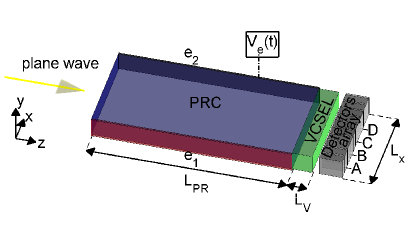
More precisely, the compact hybrid conservative-dissipative system we consider is realized by placing a centrosymmetric PRC supporting photorefractive solitons in front of a broad-area VCSEL where CSs are generated, as sketched in Fig.1. A monochromatic plane wave is launched through the PRC. By varying the voltage applied to the PRC through electrodes and a previously ”imprinted” photorefractive solitonic pattern is electro-activated and modulates the phase and intensity profile at the PRC exit. A proper choice of the plane wave amplitude and the electro-activation potential allows for cavity soliton switch on and positioning in the VCSEL cross section. We suppose that (as e.g. in Ref.Pedaci_1 ) the motion can be monitored by a photodetector array which reads the VCSEL output.
The system we consider is described by the equations of spatio-temporal field evolution and structure localization in a centrosymmetric PRC with bias DelRe_4 ; Ciatt_1 , coupled to those for a VCSEL with external driving Spinelli_1 . In the PRC the change of the space charge density due to optical photo-excitation and spatial redistribution is given by the charge continuity equation
| (1) |
where , is the space charge field and the quasi-electrostatic potential satisfies the Poisson equation where is the vacuum permittivity and is the relative static permittivity, and are the electron mobility and charge, is the Boltzmann constant and
| (2) |
is the electron density, where and are the acceptor and donor impurity density, respectively. Note that is the rate of thermal excitation of electrons, is the electron-ionized trap recombination rate, , , , is the slowly-varying amplitude of the optical electric field polarized along (at wavelength ) and is the amplitude of the uniform background illumination. Furthermore, the optical field dynamics is described by
| (3) |
where is the uniform background refractive index, and is the effective electro-optic coefficient. The dynamical equations describing radiation-matter interaction in the VCSEL are Spinelli_1
| (4) |
where is the slowly-varying amplitude of the optical electric field polarized along (at wavelength ) and scaled to the characteristic amplitude , , where is the mirror reflectivity, is the photon decay time, is the cavity detuning between and the closest cavity resonance, is the gain-to-loss ratio, is the linewidth enhancement factor, is the carriers density scaled to the transparency value , and is the background refractive index. The constant is associated with the saturation intensity where is the length of the region filled by the active medium (generally KWcm2). In the carrier density equation, is the pump current, is the carriers density decay time and we neglect radiative decay and diffusion. Here, we have chosen photorefractive parameters associated with a crystal sample of potassium lithium tantalate niobate (KLTN) at room temperature Ciatt_1 and VCSEL parameters associated to a single longitudinal mode GaAs-GaAlAs laser slightly below threshold Spinelli_1 ; Note_2 . Although the model in Ref.Spinelli_1 is intrinsically suited for a device such as a VCSEL, we reduced it to one transverse dimension, because the VCSEL is coupled with a PRC where we have previously written a waveguide. In practice, this amounts to consider either a VCSEL that is coherently injected along a stripe or a rectangular VCSEL Groneborn_1 .
The proposed technique for obtaining the generation and the fast control of CSs consists of a two-stage process: (i) a writing phase at the active wavelength m, (ii) a read-out at the non-photorefractive wavelength m and consequently the generation and speed control of CSs by means of soliton electro-activation.
The first phase (i) consists in ’writing’ the charge distribution inside the crystal; here, oppositely charged solitonic waveguides are imprinted in the PRC. Note that, in this preliminary stage, the PRC is not coupled with the cavity so that the possible reflections from VCSEL are absent. The ’writing’ is obtained by launching in the PRC a Gaussian beam , where , m, is the beam position. Optimally symmetric waveguides are obtained by periodically alternating the beam position and the writing applied voltage as follows: one sets m, V for and m, V for where the period ( is the dielectric relaxation time, generally it is of the order of minutes). The writing phase lasts .
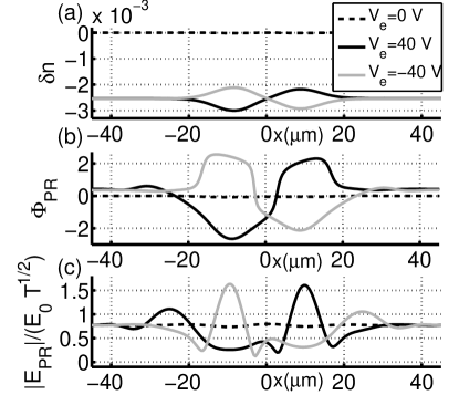
The second phase (ii), where the PRC is coupled to the VCSEL, is the fast modulation of the refractive index of the crystal which creates a field landscape in the beam impinging onto the VCSEL, capable of controlling the cavity soliton. This is achieved by launching a monochromatic plane wave with amplitude into the PRC. It propagates through the refractive index landscape created in the writing phase but is does not alter it since m is in the near-infrared where the crystal does not show any photorefractive effect Note_1 (as a consequence the carrier density does not change over time). The output field, originally uniform, then acquires a modulation which can be controlled (as we show in the following) by varying the electro-activation voltage . In Fig.2, we plot the refractive index variation (a), the phase (b) and the normalized modulus (c) of the optical electric field at the PRC exit facet () in the read out phase for the electro-activation potential V and V. During propagation, the originally transversely uniform near-infrared wave at is focussed into the guiding structure and defocussed out of the antiguiding structure. Hence, as shown in Fig.2(b) and Fig.2(c), the solitonic waveguides electro-activation induces controllable local maxima and minima of the field profile at the crystal exit. Different biases will tailor different landscapes at the PRC exit facet and thus cause different, controllable effects on the VCSEL field.
As reported e.g in Refs. Spinelli_1 ; Barland_1 there exist injected intensity ranges where a coherently driven VCSEL shows multistability between a transversely uniform low intensity configuration and CSs. Hence, by properly adjusting the electro-activation potential and the amplitude of the plane wave, we reach the necessary intensity modulation at the predetermined position to switch on a cavity soliton. No addressing pulses are required, showing that electro-optical control of spatially distributed structures can be achieved by acting on global parameters; this also allows to achieve a considerable simplification of the setup.
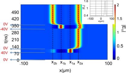
The time plot in Fig.3 shows the independent switch-on of two CSs. We inject into the VCSEL the field emerging from the PRC in the case where the initial plane wave amplitude is with no bias ( V; see black dashed lines in Fig. 2(b) and Fig. 2(c)). In this case the slight modulation of the holding beam phase and modulus is insufficient to generate a structure in the VCSEL. After ns by setting V and consequently enhancing the holding beam modulation (see black solid line in Fig. 2(b) and Fig. 2(c)) a cavity soliton is switched on at m. After ns we bring back to V the electro-activation potential and the cavity soliton persists, although it moves to the new equilibrium position of m. After further ns, the potential is set to V for the same duration as before and an independent cavity soliton now appears at m. The new cavity soliton drifts to m where it remains stable when the voltage is again set to V. The slight asymmetry with the other cavity soliton location reflects the asymmetry of the two waveguides visible in Fig.2(b). It is worth noting that the cavity soliton location at steady state is determined by both the phase and intensity gradients resulting at PRC exit. The effective control of CSs drift, via the tailoring of the plane wave profile by an electro-optically activated PRC, is proved further when the final value of the voltage at the PRC is not set to zero after cavity soliton excitation, but kept at a moderate value ranging from V to V. In this case a slight intensity and phase modulation of the wave driving the VCSEL is capable of changing the final location of the cavity soliton, which ranges from m to m for e.g. the right one.
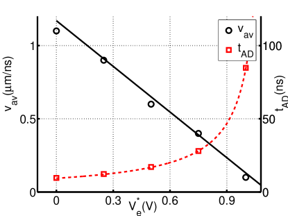
Finally, we demonstrated that the capability of the hybrid device of modelling the refractive index profile in the PRC stage allows to control the CSs motion and in particular its drift velocity. In our simulations, we monitored the passage times of the CSs (switched on at the location of detector in our layout) across a fixed location (e.g. the one corresponding to detector ) when the final bias is kept at different constant values. We denote as the time in which the cavity soliton reaches a detector distant m from (see Fig.4). The corresponding average velocity m is also plotted in the figure where it is evident that it depends linearly on and it has a maximum value of mns in excellent agreement with theoretical and experimental evidences obtained with optical gradient modelling reported in earlier literature Pedaci_1 . Thus, once the slow writing phase has been accomplished, the CSs can be detected with controlled delay by separate detectors. The CSs control can be performed by fast bias control and does not require slow phase profiling or complex set-up for collimation of addressing pulses.
In conclusion, we investigate a composite soliton-based physical system which bridges propagative (conservative) photorefractive field dynamics to its bistable (dissipative) counterpart in a microlaser. We provide a proof-of-principle demonstration of an original, high speed and integrated device for CSs generation and manipulation in a VCSEL through fast soliton electro-activation of a centrosymmetric PRC. It is worth noting that no addressing pulses are required, hence a considerable simplification of the setup is achieved. This scheme lends itself to all optical delay-line or signal buffering with a high potential for applications. Finally, we believe that the considered hybrid system can show fascinating and useful properties due to the nontrivial interaction between photorefractive solitons and CSs where either a photorefractive soliton controls cavity soliton (or viceversa a cavity solitons control a photorefractive soliton) or the CSs and photorefractive solitons are both capable of simultaneously influencing each other.
Authors thank Dr. Eugenio Del Re and Dr. Stephane Barland for many fruitful discussions. This research has been funded by the Italian Ministry of Research (MIUR) through the ”Futuro in Ricerca” FIRB-grant PHOCOS - RBFR08E7VA.
References
- (1) S. Trillo and W. E. Torruellas, eds., Spatial Solitons, Springer-Verlag, Berlin (2001).
- (2) N. Akhmediev, A. Ankiewicz, eds., Dissipative Solitons, Springer, Heidelberg (2005).
- (3) T. Ackemann, W.J. Firth, G. Oppo, Advances in Atomic, Molecular and Optical Physics 57, 323 (2009).
- (4) L.A. Lugiato, IEEE J. Quantum Electron. 39, 193 (2003).
- (5) R. Kuszelewicz, S. Barbay, G. Tissoni and G. Almuneau, EPJD 59, 1 (2010).
- (6) W. J. Firth and A. J. Scroggie, Phys. Rev. Lett. 76, 1623 (1996).
- (7) T. Maggipinto, M. Brambilla, G. K. Harkness, and W. J. Firth, Phys. Rev.E 62, 8726 (2000)
- (8) F. Pedaci, P. Genevet, S. Barland, M. Giudici and J. R. Tredicce, Appl. Phys. Lett. 89, 221111 (2006).
- (9) F. Pedaci, S. Barland, E. Caboche, P. Genevet, M. Giudici and J. R. Tredicce, T. Ackemann, A. J. Scroggie, W. J. Firth, G. L. Oppo, G. Tissoni, and R. Jäger, Appl. Phys. Lett. 92, 011101 (2008).
- (10) M. Segev and A. J. Agranat, Opt. Lett. 22, 1299 (1997).
- (11) E. DelRe, M. Tamburrini, A.J. Agrant, Opt. Lett. 25, 963 (2000).
- (12) S. Barland, J. R. Tredicce, M. Brambilla, L. A. Lugiato, S. Balle, M. Giudici, T. Maggipinto, L. Spinelli, G. Tissoni, T. Knödl, M. Miller and R. Jäger, Nature 419, 699 (2002).
- (13) M. Brambilla, L. A. Lugiato, F. Prati, L. Spinelli and W. J. Firth, Phys. Rev. Lett. 79, 2042 (1997).
- (14) L. Spinelli, G. Tissoni, M. Brambilla, F. Prati and L. A. Lugiato, Phys. Rev. A 58, 2542 (1998).
- (15) N. Sapiens, A. Weissbrod, A. J. Agranat, Opt. Lett. 34, 353 (2009).
- (16) B. Terhalle, N. Radwell, P. Rose, C. Denz, and T. Ackemann, Appl. Phys. Lett. 93, 151114 (2008).
- (17) E. DelRe, A. Ciattoni, and E. Palange, Phys. Rev. E 73, 017601 (2006).
- (18) A. Ciattoni, E. DelRe, A. Marini, C. Rizza, Optics Express 16, 10867 (2008).
- (19) In all simulations, we used the following parameters: m, mm, m, , m-3, , , m4C-2 , , , , , , ps, , ns, and nm.
- (20) S. Gronenborn, J. Pollmann-Retsch, P. Pekarski, M. Miller, M. Strösser, J. Kolb, H. Mönch, P. Loosen, Appl. Phys B 105, 783 (2011).
- (21) Note that we have not considered time dispersion effects so that the background refractive index and the electro-optic constant does not depend on frequency .