COMPARISON OF COMPRESSION SCHEMES FOR CLARA
Abstract
CLARA (Compact Linear Advanced Research Accelerator) at Daresbury Laboratory is proposed to be the UK’s national FEL test facility. The accelerator will be a MeV electron linac capable of producing short, high brightness electron bunches. The machine comprises a cell RF photocathode gun, one m and three m normal conducting S-band ( MHz) accelerating structures and a variable magnetic compression chicane. CLARA will be used as a test bed for novel FEL configurations. We present a comparison of acceleration and compression schemes for the candidate machine layout.
1 INTRODUCTION
The design approach adopted for CLARA is to build in flexibility of operation and layout, enabling as wide an exploration of FEL schemes as possible. For a full overview of the aims of the project and details of FEL schemes under consideration see [1]. To this end a range of possible accelerator configurations have been considered, a selection of this work is presented here.
A major aim is to be able to test seeded FEL schemes. This places a stringent requirement on the longitudinal properties of the electron bunches, namely that the slice parameters should be nearly constant for a large proportion of the full-width bunch length. In addition, the intention is that CLARA has the ability to deliver high peak current bunches for SASE operation and ultra-short pulse generation schemes, and low-emittance velocity compressed bunches. This flexibility of delivering tailored pulse profiles will allow a direct comparison of FEL schemes in one facility.
2 ENERGY AT MAGNETIC COMPRESSOR
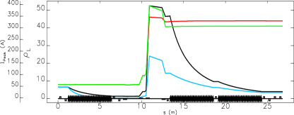
A large proportion of the FEL schemes under consideration require small correlated energy spread at the undulators, therefore when magnetic compression is to be used the compressor must be situated at substantially less than full energy. This ensures that the chirp needed at compression is able to be adiabatically damped or suppressed through running subsequent accelerating structures beyond crest. This requirement must be balanced against the fact that compressing at low energy exacerbates space-charge effects. To quantify this we use the laminarity parameter
where is the current in the slice under consideration, is the Alfven current, is the thermal emittance, and is a solenoidal focusing field (zero in our case). When this parameter is greater than , we should consider space-charge effects in the bunch evolution. To inform this we select two candidate configurations, one with magnetic compression at MeV and one at MeV. We track a candidate pC bunch through both configurations, setting the machine parameters attempt to produce a zero chirp bunch of peak current A at MeV. Tracking is carried out with ASTRA [2, 3] to the exit of the first linac section to include space-charge, followed by ELEGANT [4] taking into account the effect of cavity wakefields, longitudinal space-charge and coherent synchrotron radiation emittance dilution. Fig. 1 shows the resultant laminarities and final bunch longitudinal phase spaces.
 |
|
 |
 |
We see that in both cases space-charge should be considered, this will be achieved by re-tracking the magnetically compressed bunches in ASTRA to elucidate any deviations due to 3-d effects as compared to the purely 1-d effects included in ELEGANT. However compression at MeV does not allow us to subsequently de-chirp the bunch, note that we go no further than beyond crest in the final accelerating structures in order to avoid large jitter effects. As we wish the facility to be flexible we select a nominal compressor energy of MeV, but we achieve this by reducing the gradient in the accelerating structure before the compressor. This gives us the option of compressing at higher energy in regimes where a de-chirped bunch is not required. With the above considerations in mind we define engineering specifications for the CLARA variable bunch compressor as shown in Table 1. For flexibility, the compressor has a continuously variable and is rated for maximum energy of MeV. The ability to set a straight through path also allows investigation of purely velocity compressed bunches.
| Value | Unit | |
| Energy at compressor | 70 - 150 | MeV |
| Min. : Max. bend angle | 0 : 200 | mrad |
| Bend magnetic length | 200 | mm |
| Max. bend field | 0.5 | T |
| Min. : Max. transverse offset | 0 : 300 | mm |
| Z-distance DIP-01/04 - DIP-02/03 | 1500 | mm |
| Z-distance DIP-02 - DIP-03 | 1000 | mm |
| Max. bellows extension | 260 | mm |
| Min. : Max. | 0 : -72 | mm |
| Max. from () | 0 : 10 | mm |
| Max. from () | 1.5 | mm |
3 BUNCH FOR SEEDING SCHEMES
A seeded FEL scheme requires constant bunch parameters over a large proportion of the bunch. This reduces the sensitivity to timing jitter between the seed laser and electron bunch. Specifically, we require a constant peak current of A over fs of the bunch, with zero chirp, constant emittances and zero transverse offset. In order to achieve this we must cancel the curvature that originates from RF acceleration. It is possible to do this purely magnetically, although typically it is done with higher harmonic RF. As harmonic RF entails additional expense we compare two schemes, a bunch compressor with non-linear elements inserted, and a fourth harmonic X-band cavity.
3.1 LINEARISATION VIA NONLINEAR CHICANE
The lower right plot of Fig. 1 shows residual curvature in the longitudinal phase space. This can be flattened by changing the sign of the natural term in the bunch compressor chicane. To achieve this sextupoles were added to the chicane. The number, positions and strengths of these were parameters of an optimisation. We impose the constraints that the cm, the derivative of dispersion with respect to energy and it’s derivative with respect to should be zero on exit of the chicane, the projected emittances should not exceed mm mrad and the sextupoles m-2. This constraint set was chosen by trial and error.
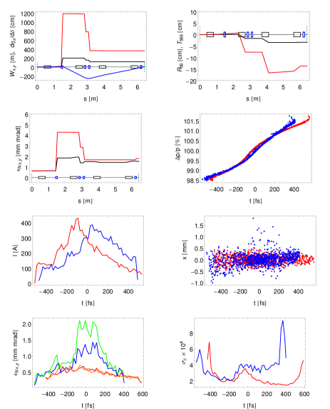
Figure 2 shows the optimisation results. Flattening the longitudinal curvature is relatively straightforward however the chromatic properties are easy to spoil, resulting in increased projected and slice emittance. Up to six sextupoles were tried with similar results. These nonlinear compressors have also been studied under energy jitter and the bunch parameters found to vary substantially.
3.2 LINEARISATION VIA HARMONIC RF
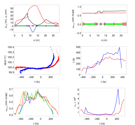
We insert a fourth harmonic m structure immediately prior to the magnetic compressor. An optimisation [5] was then performed with variables being the harmonic voltage and phase, the off crest phase of the preceding linac and the angle of the compressor dipoles. Results for two candidate tunings are shown in Fig. 3. The peak voltage on the linearising cavity is MV/m. It can be seen that the additional complication of a harmonic cavity is justified by ability to predictably tailor longitudinal phase space.
4 VELOCITY BUNCHING
An alternative to magnetic compression is to use velocity bunching in the low energy section of the accelerator. The first m linac section is set to the zero crossing to impart a time-velocity chirp along the bunch. The bunch then compresses in the following drift space. The second linac section is positioned at the waist of the bunch length evolution after m of drift to rapidly accelerate the beam and capture the short bunch length. Solenoids are required around the bunching section to control the transverse beam size and prevent emittance degradation. ASTRA was used to track until the end of the second linac module followed by ELEGANT. The quadrupoles between the first and second linac sections are switched off in order to keep the beam axially symmetric, and the bunch compressor set to zero angle. An evolutionary algorithm was used to optimise the beamline for both bunch length and transverse emittance. We present two tunings with pC bunch charge.
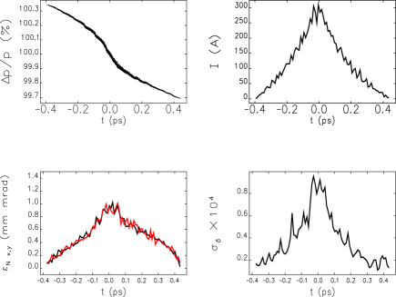
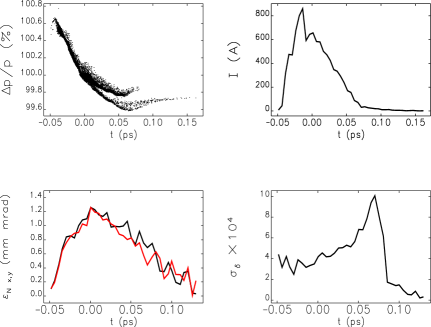
Fig. 4 shows a bunch with similar peak current and current profile to the non-linearised magnetically compressed bunch of Fig. 2-5. This is achieved at half the total bunch charge, with lower slice energy spread, but higher slice emittance. In Fig. 4 we show that a similar peak current to the non-linearised magnetically compressed bunch of Fig. 2-5 is easily achieved with smaller slice energy spread but higher slice emittance. Fig. 5 shows a beam tuned for peak current at the exit of the second linac module. The peak current then degrades along the accelerator. This bunch has the capabilities to provide single-spike SASE FEL operation.
5 CONCLUSIONS
This initial study has established an accelerator layout for CLARA that is inherently flexible in the pulse profiles it is capable of producing. We have shown this by simulating bunches suitable for seeded and SASE FEL operation. Further work will entail jitter tolerance analysis of the presented configurations.
References
- [1] J. A. Clarke et. al., TUPPP066, these proceedings
- [2] K. Flöttmann, http://www.desy.de/~mpyflo.
- [3] J. W. McKenzie & B. L .Militsyn, THPC132, IPAC 11.
- [4] M. Borland, Advanced Photon Source, LS-287 (2000).
- [5] R. Luus & T. H. I. Jaakola, AIChE Journal 19, 760 (1973).