Mode bifurcation on the rythmic motion of a micro-droplet under stationary DC electric field
I Introduction
Accompanied by the development of microtechnology, such as MEMS and TAS, there is increasing interest on the methodology to realize a desired motion of a micro object in a solution environment. It is well known that the principle to create an electric motor in a macro system is not applicable to micro system because of the enhanced sticky interaction and higher viscosity in micrometer sized system. On the other hand, living organisms generate various motions on microscopic scale under isothermal condition. Despite the past intensive studieshiratsuka ; vandenheuvel , the underlying mechanism of the biological molecular motors has not been fully unveiled yet. Under such development status of science and technology on micro-motor sat the present, we report a simple motoring system which work smoothly in a microscpic scale.
Recently, we found that rhythmic motion is generated for an aqueous droplet in an oil phase under DC voltage on the order of 50 - 100 V. We have already reported some experiments and models for a w/o droplet under DC electric field.hase ; takinoue There are some reports about experiments of w/o droplets moving under electrical fieldjung ; mochizuki , bouncing and being absorbed on a surface between water and oilristenpart , deforming and splitingEow ; teh . Manipulating this kind of droplet, which is interesting as the model of the cellpietrini ; tawfik ; hase2 , the micro-sized reactor, by optical tweezerskatsura , by micro channelatencia ; link . And manipulating the cells or micro objects by electrical field has been attemptedvoldman , to know manipulating this kind of droplets in detail will help this in the future. In the present article, we will show that rhythmic motion on micro-droplet is induced under the DC potential on the order of several volts. We will also propose a simple mathematical model to reproduce the rhythmic motion and mode bifurcation.
II Experimental
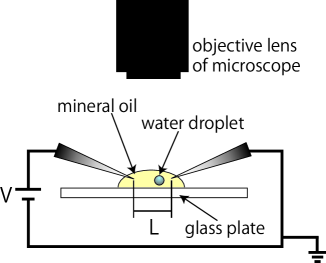
A schematic illustration of the experimental setup is given in FIG.1. A water droplet was suspended in mineral oil on a glass slide, and constant voltage was applied to the droplet using cone-shaped tungsten electrodes. Droplet motion was observed using an optical microscope (KEYENCE , Japan).
The w/o droplet was generated using a vortex mixer as follows. We prepared mineral oil including surfactant: 10m surfactant, dioleylphosphatidylcholine (DOPC) (Japan), was solved in mineral oil (Nacalai Tesque, Japan) by 90 min sonication at . 2l ultrapure water (Millipore, Japan) was added to 100 l of the prepared mineral oil, and then agitated by a vortex mixer for approximately 3 s.
III Results
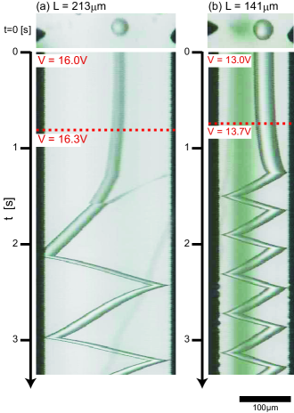
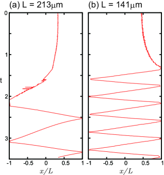
FIG.2 exemplifies the motion of a droplet under DC electric field, indecating the occurrence of the periodic go-back motion between the electrodes accompanied by the increase of the electical potential. In the experiments, we observed two following types of behavior: oscillatory and stationary. These behaviors switch each other depending on the applied voltage. When the distance between two electrodes was 213m [FIG.2(a)], the droplet started the motion with the applied voltage above 16.3 V. When the distance between two electrodes was 141m [FIG.2(b)], the droplet started moving with the applied voltage above 13.7 V.
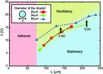
FIG.3 shows the diagram of the mode of droplet behavior depending on the applied voltage with the size of the droplet is —-. When the distance of two electrodes is below approximately 70m , droplets are sticked to an electrode (adhered). The diagram indecates that the threshold of applied voltage is roughly propotional to the distance between two electrodes.
IV Discussion
We propose a model to describe the oscillatory-stationary motion of w/o droplets. In an eqation of motion at a micrometer scale, a viscosity term is more dominant than inertia term because the Reynolds number, , is rather small; , where and are the density and viscosity of the mineral oil, respectively, and and are the velocity and diameter of the water droplet. Therefore, an over-damped eqation of motion under the constant electric field, , is given by
| (1) |
where is a coefficient of viscosity resistance, and represents the viscosity resistance for a moving droplet with diameter and velocity . and indicate an electric force and a dielectric force acting on the droplet with charge and polarizability ( ̵̓I Ȓl)jones .
Here we assume that the time-dependent rate od the charge, , is described as
| (2) |
where is the proportionality coefficient, and is the constrant is proportional to the magnitude of the electrical field. The first term of this means the time-dependence of charge is in proportion to the number of lines of electric force. The second term means the charge leak, and is the relaxing time.
We would like to consider the condition where the droplet stays on the same position between two electrodes. When the electric field can be written as , The force on the second term in the right hand of Eq. (1) is caused by the number of the lines of electric force penetrating the droplet. Comparing with the size of droplet, the change of along axis can be neglected. By considering the symmetry of the system, we simply adapt that the change of along axis is written as
| (3) |
Then the component of eq.(1) is given as
| (4) |
For simplicity, we introduce the following parameters: , and . Then Eq.(2) and Eq.(4) can be written as
| (5) | |||||
| (6) |
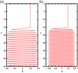
FIG.4 shows the result of numeric calculation with these equations, where the time and space scales , and , are arbitrary. The change of the distance between the electorodes corresponds to the change of the magnitude of the electric field. For example, if becomes larger, and become smaller. In FIG.4, and in (b) are larger than those in (a). The frequency of the back-and-force motion of the droplet is faster when the electric field between the electrodes becomes stronger. Thus, our numerical model reproduces the essential aspect of the rhythmic motion of a droplet under DC voltage.
V Acknowledgements
References
- (1) Y. Hiratsuka, M. Miyata, T. Tada, and T. Q. P. Uyeda, Proc. Natl. Acad. Sci. U.S.A. 103, 13618 (2006).
- (2) M. G. L. van den Heuvel and C. Dekker, Science 317, 333 (2007).
- (3) Hase, et al., PRE 74, 046301(2006).
- (4) Takinoue, et al. Appl. Phys. Lett. 96, 104105 (2010)
- (5) T. Mochizuki, Y. Mori, and N. Kaji, AIChE J. 36, 1039 (1990).
- (6) Y. Jung, H. Oh, and I. Kang, J. Colloid Interface Sci. 322, 617 (2008).
- (7) W. D. Ristenpart, J. C. Bird, A. Belmonte, F. Dollar, and H. A. Stone, Nature (London) 461, 377 (2009).
- (8) J. S. Eow, M. Ghadiri, and A. Sharif, Colloids Surf., A 225, 193 (2003).
- (9) S. Teh, R. Lin, L. Hung, and A. Lee, Lab Chip 8, 198 (2008).
- (10) A. V. Pietrini and P. L. Luisi, ChemBioChem 5, 1055 (2004).
- (11) D. S. Tawfik and A. D. Griffiths, Nat. Biotechnol. 16, 652 (1998).
- (12) M. Hase and K. Yoshikawa, J. Chem. Phys. 124, 104903 (2006).
- (13) S. Katsura, A. Yamaguchi, H. Inami, S. Matsuura, K. Hirano, and A. Mizuno, Electrophoresis 22, 289 (2001).
- (14) D. R. Link, E. Grasland-Mongrain, A. Duri, F. Sarrazin, Z. Cheng, G. Cristobal, M. Marquez, and D. A. Weitz, Angew. Chem. Int. Ed. 45, 2556 (2006).
- (15) J. Atencia and D. J. Beebe, Nature (London) 437, 648 (2005).
- (16) J. Voldman, Annu. Rev. Biomed. Eng. 8, 425 (2006).
- (17) T. B. Jones, Electromechanics of Particles (Cambridge University Press, New York, 1995).