Nano dust impacts on spacecraft and boom antenna charging
Accepted for publication in Astrophysics & Space Science
Abstract
High rate sampling detectors measuring the potential difference between the main body and boom antennas of interplanetary spacecraft have been shown to be efficient means to measure the voltage pulses induced by nano dust impacts on the spacecraft body itself (see Meyer-Vernet et al, Solar Phys. 256, 463 (2009)). However, rough estimates of the free charge liberated in post impact expanding plasma cloud indicate that the cloud’s own internal electrostatic field is too weak to account for measured pulses as the ones from the TDS instrument on the STEREO spacecraft frequently exceeding . In this paper we argue that the detected pulses are not a direct measure of the potential structure of the plasma cloud, but are rather the consequence of a transitional interruption of the photoelectron return current towards the portion of the antenna located within the expanding cloud.
Keywords Interplanetary dust and gas, 96.50.Dj; plasma interactions with antennas, 52.40.Fd; photoemission, 79.60.-i
1 Introduction
Dust particles in the nano and micro meter range hitting the main body of interplanetary spacecraft have been shown to produce a transient potential difference between the antenna booms and the spacecraft main body (see Meyer-Vernet et al., 2009, and references within). For large grains, in the micrometer range, the measured potential difference is primarily due to recollection of the electrons from the impact generated expanding plasma cloud by the spacecraft main body which under standard solar wind conditions at 1AU is positively charged due to photoelectric charging of its sunlight exposed parts. The temporary accumulation of a negative charge on the spacecraft’s body accounts for a variation of the potential difference between the spacecraft and the antenna booms by an amount
| (1) |
where is the spacecraft body capacitance and an order unity gain factor. The potential pulse associated with such large grain impacts being solely due to charging of the spacecraft body, one expects the signal to be of similar amplitude on all antennas. Many thousands of such events displaying simultaneous and similar amplitude pulses on different antennas have effectively been recorded on the three antennas mounted on the STEREO spacecraft (Zaslavsky et al., 2012).
Besides this group of events, STEREO has recorded an even larger sample of events where the voltage pulse is roughly equal on two antennas and larger, by a factor , on the third one. Zaslavsky et al. (2012) interpret this second group of events as the signature of the impact of smaller and faster grains in the nano meter size domain. As for the micro meter grains the two weak pulses are due to recollection of electrons from the expanding plasma cloud and are an indirect measure of the cloud’s free charge content via Equation (1). As briefly described in Appendix A of Zaslavsky et al. (2012), the larger pulse measured on one of the three antennas is due to the action of the expanding cloud’s electric field on the photoelectrons surrounding this particular antenna. In contrast, at most a small fraction of the two antennas presenting a weak signal is attained by the expanding cloud without a significant effect on the photoelectrons emitted by their surfaces. The reason this scenario does not apply in case of micro meter grain impacts is that the latter liberate a larger quantity of free charges than the nano meter grain impacts so that the dissipation of the expanding cloud into the ambient plasma occurs for cloud dimensions large enough () to envelop all three antennas.
In this paper we present a semi-quantitative scenario to explain the strong positive charging of a boom antenna finding itself within a nano dust induced plasma cloud. We argue that the intrinsic electric field within the cloud is too weak to account for the measured voltage pulse. However, this field is shown to be strong enough to transitionally reduce the number of photoelectrons falling back onto the antenna leading to a positive net current towards its surface. Except otherwise specified, SI units are used throughout the paper.
2 Basic hypothesis and simplifications
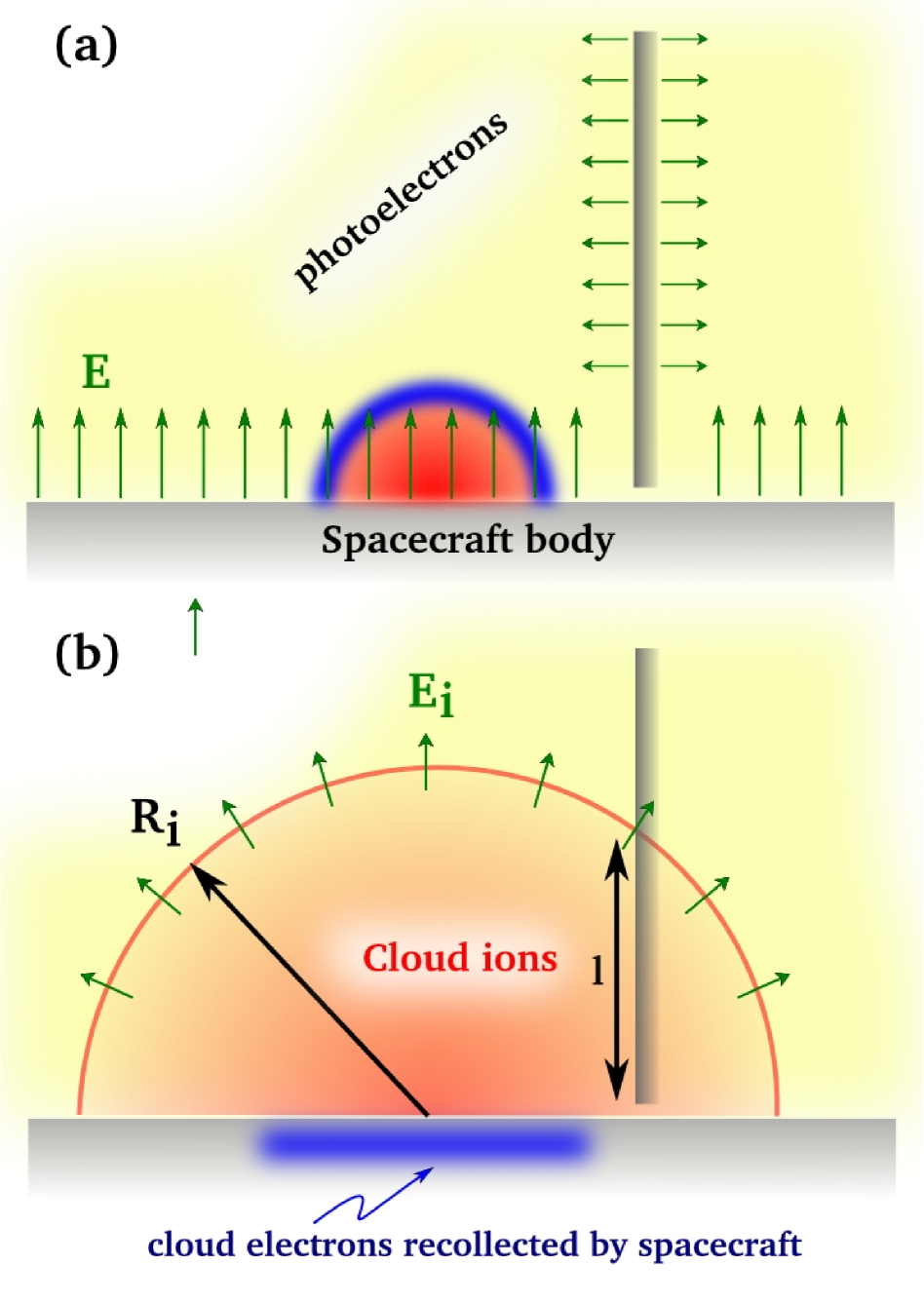
We suppose that a dust grain hits the spacecraft body at some distance from the base of an antenna boom in the idealised geometrical set-up illustrated in Figure 1a. For simplicity we assume that the spacecraft surface is plane with a cylindrical antenna oriented perpendicularly to it. The spacecraft being exposed to the solar radiation, both the spacecraft and the antenna are positively charged by photoionisation with a permanent “atmosphere” of photoelectrons around them. The characteristic energy of a photoelectron is of the order of 1 to 4 eV (see Henri et al., 2011, and references within) and the electric field near the sunlight exposed surfaces is a few V/m. We emphasise that at 1 AU the photoelectron current from a sunlit surface of typical conducting spacecraft material is of the order per surface unit normal to the Sun direction. This largely exceeds the flux of electrons provided by the solar wind which for a density of 10 electrons per and a temperature gives a 50 times smaller current (neglecting the effect of the spacecraft potential and the contribution from the ions) , where is the elementary charge, the electron mass. Even considering that the solar wind electrons are collected at the same rate all over the antenna surface whereas photoelectrons are only emitted by the one half of the antenna exposed to solar radiation and that the photoelectron flux is further reduced by a factor where is the angle of the antenna axis with respect to the direction of the Sun, the emitted photoelectron current remains much stronger than the collected current from the ambient plasma. On STEREO the former is still 13 times stronger than the latter (see Henri et al., 2011). To counter an endless charging of the spacecraft, most of the emitted photoelectrons (over for STEREO) are therefore doomed to fall back onto the emitting surface. To simplify the discussion we then make the step to neglect the small proportion of photoelectrons escaping to infinity whose net current balances the currents provided by the ambient plasma. In any case, the zero photoelectron current assumption is not a crucial one as we do merely require that a substantial (not necessarily the totality) of the photoelectrons be recollected.
The crucial point is that the extension of the cloud of photoelectrons is much larger than the antenna radius on STEREO. Indeed, a rough estimate of the Debye length of the photoelectron cloud can be obtained by assuming that the distribution of the radial velocities near the antenna surface is Maxwellian where is the photoelectron thermal velocity. Equating the total current directed away from the antenna surface ( is the length of the antenna) and the total photoelectron current from the antenna we obtain an estimate of the density near the antenna surface:
| (2) |
Substituting the density into the expression for the Debye length yields
| (3) |
where is the vacuum permittivity and the Boltzmann constant. Setting and taking an average value for one has which is indeed much larger than the antenna radius . We note in passing that the Debye length of the ambient plasma at 1AU is typically so that it can be safely ignored in the present context.
After a dust impact on the spacecraft body, as schematically illustrated in Figure 1a, a hemispherical overall neutral plasma cloud made of ions (red) and electrons (blue) and neutrals expands away from the impact point. In the early phase of the expansion the electric field intensities within the cloud are stronger than the V/m field intensity surrounding the spacecraft and the expansion is not affected by the environment. At some stage the electric field within the expanding cloud has decreased below the spacecraft’s field. The cloud electrons become captured by the spacecraft leaving a positively charged cloud continue the expansion eventually encompassing a non negligible portion of the antenna (Figure 1b). In the next section we evaluate the field intensity within the cloud and argue that this field is strong enough to temporally prevent a significant fraction of photoelectrons to fall back onto the antenna.
2.1 Early phase of the expansion
Let us assume that a dust grain of hits the spacecraft body at a velocity of 400 km/s. The empirical formula (2) in McBride and McDonnell (1999) predicts that the post impact released free charge is . For comparable ion and electron temperatures, electrons tend to detach from the ions forming an electron precursor as illustrated in Figure 1a (e.g. Pantellini et al., 2012). The strongest possible electric field intensity sensed by the electrons in the precursor is obtained in the limiting case of complete electron-ion charge separation. If is the radius of the ion sphere, the maximum field intensity near its edge is at most , or less in case of partial charge separation. Even in the limit of complete charge separation this field is smaller than the typical spacecraft electric field intensity of 5V/m by the time the cloud has grown to a small radius of only. Upon further expansion its intrinsic field falls below the spacecraft’s own field which then starts recollecting electrons from within the cloud. The time for an electron leaving the spacecraft with a normal velocity to reach its maximum height can be estimated by assuming that it only feels the constant spacecraft electric field, i.e. . The non constant cloud field is also directed towards the spacecraft and may further reduce . For an electron with an initial energy of the order the photoelectron thermal energy and under the assumption of energy equipartition we have . Setting and, as before, it then takes a time to reach a maximum height above the spacecraft . This is an upper estimate for as we have assumed that the electrons are collisionless and insensitive to the cloud’s field. In addition, cloud electrons are expected to cool during expansion (e.g. Murakami and Basko, 2006; Beck and Pantellini, 2009), which further favours fast recollection. The bottom line is that the electrons of the cloud are recollected by the spacecraft before its maximum extension has been reached, i.e. before its density has decreased to a value comparable to the surrounding solar wind plasma density. Indeed, for a spherical cloud of charge , and a solar wind density the relation gives . The late evolution of the cloud, when the chance of having a significant portion of the antenna within the cloud itself is high, can be assumed to be hemispherically shaped as shown in Figure 1b. At this stage, all electrons from the cloud have been recollected by the spacecraft leaving the cloud with a total positive charge .
The electric field near the edge of a spherical cloud is then given by the Coulomb potential
| (4) |
We emphasise that the field given by (4) is the cloud’s field after its electrons having been recollected by the spacecraft, which is by definition smaller than the spacecraft field . Because of the dependence one can even assume that during this late phase of the expansion . We shall see that despite being small, the cloud’s field is generally strong enough to drastically reduce the photoelectron return current towards the antenna inducing a transitional modification of the antenna’s net charge.
2.2 Photoelectron dynamics
During the time periods between successive impacts we may assume a time independent electrostatic potential in the plasma surrounding the antenna. This assumption holds for plasma conditions that vary slower than both the inverse of the ambient plasma frequency and the photoelectron plasma frequency . The total energy of a photoelectron in such a static field can be written as
| (5) |
where is the distance to the antenna axis, the radial component of the velocity, the (constant) velocity component along the antenna axis and the angular momentum with being the azimuthal velocity component. Both the total energy and the angular momentum are conserved quantities as long as is time independent. As already pointed out, a majority of the photoelectrons emitted by the antenna must fall back onto its surface as this is the only way to balance the net (outflowing + inflowing) photoelectron current from the antenna and the currents from the ambient plasma. The size of the cloud formed by these ballistic photoelectrons is expected to be much larger than the antenna radius (cf Figure 1), since the photoelectron Debye length estimated in (3) is .
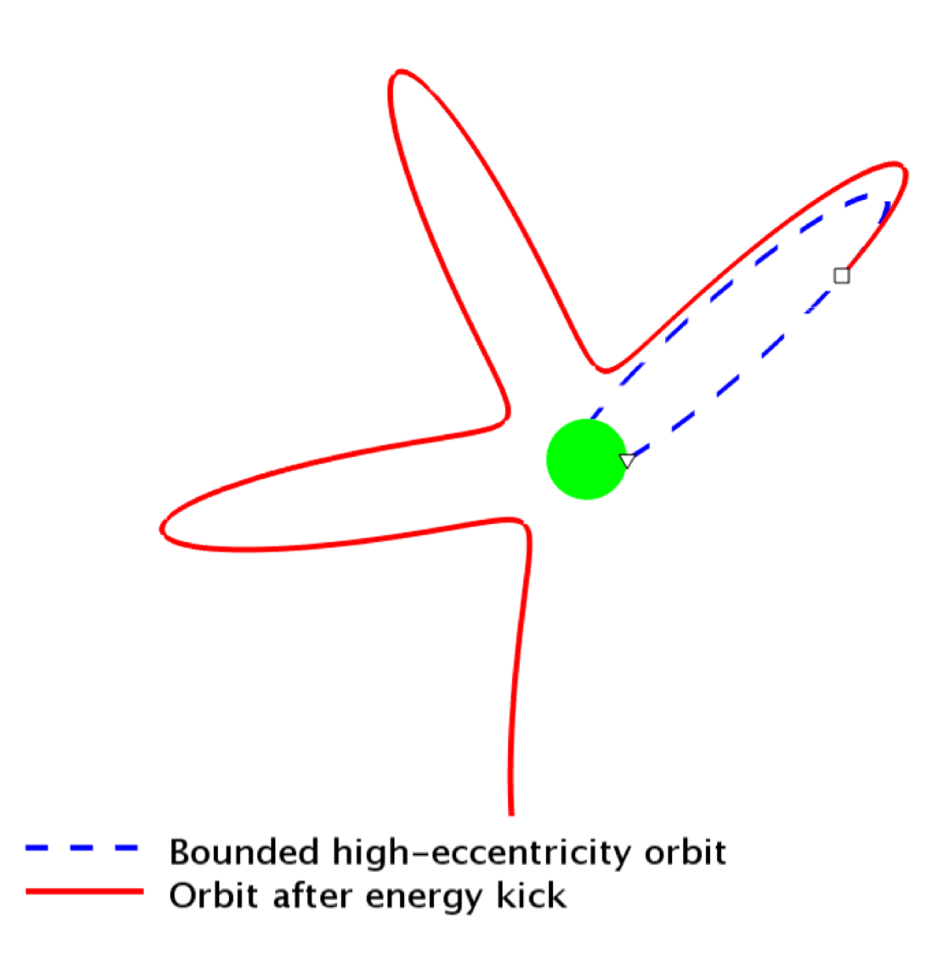
The only way for photoelectrons to be emitted and recollected by a thin antenna while forming an extended cloud much larger than is to move on high eccentricity orbits similar to the blue (dashed) curve in figure 2. As on most of a typical photoelectron trajectory, is negligible with respect to and equation (5) can be approximated by an equation for the radial component of the velocity only:
| (6) |
where we have assumed that there is no electric field along the -axis so that . Averaging (6) over a large number of trajectories, and setting , leads to the formal expression . Explicit computation of averages requires a detailed knowledge of the distribution of the electrons injected at and the potential energy profile . We limit ourselves to an order of magnitude estimate by assuming equipartition between potential and kinetic energy and an energy of per degree of freedom at , i.e. .
On the other hand, conservation of the angular momentum conservation implies that the azimuthal kinetic energy decreases with distance as . Assuming the same characteristics for the photoelectron cloud as in Section 2 and given an antenna radius , an average kinetic energy at of and an mean position one has . The average azimuthal energy of the photoelectron is so small that it can be easily increased by a factor larger than unity in the field of the expanding plasma cloud. Let us verify this statement. As previously noted a nano dust of kg hitting a spacecraft at km/s produces a cloud with a free charge . In order for the electrostatic voltage to be equal to requires which is well beyond the size of the cloud at the time it merges with the surrounding plasma. We note that even if the liberated free charge was only one tenth of the above estimate based on the empirical formula (9) in Meyer-Vernet et al. (2009), the intrinsic field of the cloud would still be strong enough to disconnect most of the photoelectrons from the antenna surface. In other words, during the whole time of the expansion, the cloud’s electrostatic field is potentially strong enough to increase the azimuthal velocity of the ballistic photoelectrons by a factor much larger than unity, while letting their total kinetic energy essentially unaffected. Only in the very special case of a cloud centred exactly at the base of the antenna the azimuthal field component is zero and the mechanism inoperative.
A qualitative illustration of the effect of a slight modification of the total kinetic energy of a photoelectron on a high-eccentricity orbit is shown in Figure 2. A photoelectron is emitted at the surface of the positively charged antenna of radius with enough energy to escape to a distance . If the electrostatic potential of the antenna is time independent and if the total energy of the electron is negative, the electron is doomed to fall back onto the antenna’s surface (blue dashed line). Its contribution to the net current from the antenna is therefore zero. However, a small energy kick to the electron at an arbitrary position (marked by a square on the figure) may be sufficient to alter the orbit such that it does no longer cross the antenna’s surface. The emitted electron being unable to return towards the antenna, the latter increases its charge by a positive elementary charge corresponding to a net positive current.
In Figure 2 the electrostatic field is given by the modified Bessel function where can then be seen as the characteristic radial extension of the photoelectron cloud. Such a field may represent a fair approximation of the electrostatic field around a positively charged antenna in the linear regime (Bystrenko and Bystrenko, 2008), i.e. at some distance from the antenna but is certainly incorrect near where potential and kinetic energy must be of same order. Without pretending to reproduce in detail a real case, which is not the purpose of the present work, we have arbitrarily set and the electron has been injected at the antenna surface at a angle with respect to the radial direction and an energy corresponding to 0.83 times the escape energy. An energy kick in the transverse direction corresponding to 0.05 times the initial kinetic energy is given to the electron at the point (marked by a square) where its radial velocity has decreased to 1/3 of its initial value.
2.3 Antenna charging
Let us suppose, as illustrated in Figure 1b that represents the length of the part of the antenna located inside the expanding plasma cloud at the time of its maximum extension, before it merges with the ambient plasma. Assuming that the orbits of the majority of the photoelectrons emitted by the sunlit surface of the portion of antenna located inside the cloud become orbitally disconnected from the antenna’s surface during a time , the excess charge which accumulates on the antenna can be estimated to
| (7) |
In (7) is a typical photoelectron current at 1AU and is a characteristic time for the population of photoelectrons to restore the original axisymmetric antenna potential. The smallest possible value for is determined by the inverse of the photoelectron plasma frequency , which is the fastest collective time scale for the photoelectrons, so that . The time interval , during which the antenna increases its positive charge, is a function of the spatially varying photoelectron density . The spatial dependence of the photoelectron density makes it difficult to give a number to feed into (7). Assuming an average density for the extended cloud (to be compared with the estimate at the surface from equation (2)) one has and an estimate . The induced voltage pulse for an antenna of capacitance and a gain is given by
| (8) |
For the 6m antennas mounted on STEREO and (Bale et al., 2008) the expected voltage pulse may then be as large as with and . Taking for a cloud of radius , the expected voltage pulse is which is of the order of the average pulses measured on STEREO for the so-called single hits (see figure A.10 in Zaslavsky et al., 2012).
From equation (7) it appears that the charge collected by the antenna is proportional to its radius . On the WIND spacecraft, also located at 1AU from the Sun is approximately 60 times smaller than on STEREO (Kellogg and Bale, 2001) which implies that the voltage pulses associated with impacts of nano dusts are expected to be smaller by this same factor with a typical expected amplitude of , only. Such pulses are too weak to emerge from the natural electrostatic plasma fluctuations and are therefore undetectable on WIND, not even considering that WIND’s antennas have a larger capacitance than STEREO’s. Dust impact detections on the Cassini spacecraft at Saturn, which carries radio instruments similar to STEREO are also problematic as the photoelectron current at Saturn is roughly 80 times smaller than at 1 AU with a commensurately smaller signal.
3 Conclusions
Estimates of the electrostatic potential through a plasma cloud generated by nano meter sized dust grain impacts on a spacecraft’s main body suggest that the cloud’s field is too weak to account for the voltage pulses observed on STEREO (see Pantellini et al., 2012). To solve the issue we suggest that the strong voltage pulses measured between one individual boom antenna and STEREO’s main body is primarily the consequence of a charging of the antenna due to a temporary interruption of the photoelectron return current. The interruption of the return current only affects the fraction of the antenna finding itself within the plasma cloud at the time of its maximum expansion. This happens because the photoelectron “atmosphere” bounded to the antenna extends to distances much larger than the antenna radius itself. This is characteristic of situations where the photoelectron Debye length is . Under such circumstances most photoelectrons emitted by the antenna have high eccentricity orbits, meaning that on most of their trajectory their velocity is essentially oriented radially with respect to the antenna axis. Angular moment conservation implies that the azimuthal velocity component of a photoelectron decreases with distance as and, consequently, its azimuthal energy as . As most photoelectrons are located at a large distance from the antenna , even the small energy kick given to them by the expanding plasma cloud can be strong enough to change their azimuthal velocity (and therefore their angular momentum) by a factor larger than unity. Such a strong increase of the angular momentum is generally sufficient to disconnect the corresponding photoelectron from its ballistic trajectory connected to the antenna’s surface which therefore undergoes a net loss of negative charges.
The positive charging of the antenna continues until both the perturbing cloud becomes diluted in the ambient plasma and the cylindrical symmetry of the potential around the antenna is reestablished, i.e. at least during a time of the order of a photoelectron plasma oscillation.
This scenario is compatible with the fact that nano dust impacts are not readily detectable on radio spectrograms from radio receivers on WIND at Earth orbit and Cassini at Saturn, as in both cases the emitted photoelectron current is strongly reduced due to either a smaller antenna radius (WIND) or a larger distance from the Sun (Cassini) than STEREO.
References
- Bale et al. (2008) Bale, S.D., Ullrich, R., Goetz, K., Alster, N., Cecconi, B., Dekkali, M., Lingner, N.R., Macher, W., Manning, R.E., McCauley, J., Monson, S.J., Oswald, T.H., Pulupa, M.: Space Science Reviews 136, 529 (2008)
- Beck and Pantellini (2009) Beck, A., Pantellini, F.: Plasma Physics and Controlled Fusion 51(1), 015004 (2009)
- Bystrenko and Bystrenko (2008) Bystrenko, O., Bystrenko, T.: Physica Scripta 78(2), 025502 (2008)
- Henri et al. (2011) Henri, P., Meyer-Vernet, N., Briand, C., Donato, S.: Physics of Plasmas 18, 2308 (2011)
- Kellogg and Bale (2001) Kellogg, P.J., Bale, S.D.: Journal of Geophysical Research 106(A9), 18721 (2001)
- McBride and McDonnell (1999) McBride, N., McDonnell, J.A.M.: Planetary and Space Science 47, 1005 (1999)
- Meyer-Vernet et al. (2009) Meyer-Vernet, N., Maksimovic, M., Czechowski, A., Mann, I., Zouganelis, I., Goetz, K., Kaiser, M.L., Cyr, O.C.S., Bougeret, J., Bale, S.D.: Solar Physics 256, 463 (2009)
- Murakami and Basko (2006) Murakami, M., Basko, M.M.: Physics of Plasmas 13, 012105 (2006)
- Pantellini et al. (2012) Pantellini, F., Landi, S., Zaslavsky, A., Meyer-Vernet, N.: Plasma Physics and Controlled Fusion 54(4), 045005 (2012). doi:10.1088/0741-3335/54/4/045005
- Zaslavsky et al. (2012) Zaslavsky, A., Meyer-Vernet, N., Mann, I., Czechowski, A., Issautier, K., Le Chat, G., Pantellini, F., Goetz, K., Maksimovic, M., Bale, S.D., Kasper, J.C.: Journal of Geophysical Research in press (2012). doi:10.1029/2011JA017480