now at ]Thomas Jefferson National Lab, Newport News, VA 23606
Higher Order Spin Resonances in a 2.1 GeV/c Polarized Proton Beam
Abstract
Spin resonances can depolarize or spin-flip a polarized beam. We studied 1st and higher order spin resonances with stored 2.1 GeV/ vertically polarized protons. The 1st order vertical () resonance caused almost full spin-flip, while some higher order resonances caused partial depolarization. The 1st order horizontal () resonance caused almost full depolarization, while some higher order resonances again caused partial depolarization. Moreover, a 2nd order resonance is about as strong as some 3rd order resonances, while some 3rd order resonances are much stronger than a 2nd order resonance. One thought that spin resonances are far stronger than , and that lower order resonances are stronger than higher order; the data do not support this.
pacs:
29.27.Bd, 29.27.Hj, 41.75.AkTo study the strong interaction’s spin dependence with polarized proton beams, one must preserve and control the polarization during acceleration and storage dgcrabb ; spin00 ; spin02 ; spin04 ; spin06 ; spin08 . This can be difficult due to many 1st and higher order depolarizing (spin) resonances. For vertically polarized beams in flat accelerators, it was thought that vertical spin resonances should be stronger than horizontal resonances, and lower order resonances should be stronger than higher order resonances ssc ; fermi . There were several theoretical attempts to calculate the strengths of higher order spin resonances Tepikian ; Mane ; Hoffstaetter . Some 2nd order and synchrotron-sideband resonances were seen in electron rings Johnson and proton rings Goodwin . Moreover, a 2nd order proton resonance was studied in detail at IUCF Ohmori . We used 2.1 GeV/ polarized protons stored in the COSY synchrotron for a detailed experimental study of higher order spin resonances. Our preliminary data was presented at SPIN 2004 adk , but both the data and the never-presented data needed significant reanalysis. The properly reanalyzed data presented here suggest that many higher order spin resonances, both and , must be overcome to accelerate polarized protons to high energies.
In flat circular rings, a beam proton’s spin precesses around the vertical fields of the ring’s dipole magnets. The spin tune is the number of spin precessions during one turn around the ring, where is the proton’s gyromagnetic anomaly and is its Lorentz energy factor. Horizontal magnetic fields can perturb the proton’s stable vertical polarization creating a spin resonance stora ; courant ; montague ; sylee . Spin resonances occur when
| (1) |
where , and are integers; and are the horizontal and vertical betatron tunes, respectively. Imperfection spin resonances occur when . Intrinsic spin resonances occur when either or , or both; the sum defines each resonance’s order.
The experiment’s apparatus, including the COSY storage ring maier ; lehrach02 , EDDA detector schwarz ; altmeier , electron cooler stein , low energy polarimeter (LEP) chiladze , injector cyclotron, and polarized ion source eversheim ; weidmann ; felden , were shown in Fig. 1 of Ref leonova04 . The beam from the polarized ion source was accelerated by the cyclotron to 45 MeV and then strip-injected into COSY.
Before this injection, the LEP measured the beam’s polarization to monitor its stability. The cylindrical EDDA detector schwarz ; altmeier measured the beam’s polarization in COSY after crossing the resonances. We reduced its systematic errors by cycling the polarized source eversheim ; weidmann ; felden between the up and down vertical polarization states. The measured flat-top polarization, before crossing any resonances, was typically about 75%.
In the COSY ring, the protons’ average circulation frequency was MHz at 2.1 GeV/, where their Lorentz energy factor was . For these parameters, the spin tune was . During injection, acceleration and at the beginning of the flat-top the betatron tunes and were kept fixed at and , respectively. This kept both betatron tunes away from any 1st, 2nd, or 3rd order spin resonances on flat-top. After reaching the flat-top, we varied the ring quadrupoles’ currents to vary either or , while keeping the other tune fixed; then we measured the polarization.
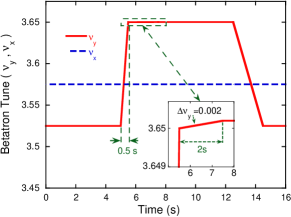
Figure 1 shows the betatron tunes’ behavior in a typical COSY cycle, during the higher order vertical () spin resonance study; we first ramped rapidly from to some value between during 0.5 s. Next we slowly ramped through a very small tune range of about during 2 s, with fixed at ; then we measured the polarization. The rapid ramp reduced the effects of the resonances between the injection tune of and the start of the slow ramp, while each slow ramp enhanced the effect of any spin resonance in its very small range.
The Low Energy Polarimeter (LEP) monitored the beam polarization before injection into COSY. The measured LEP asymmetries indicated that the initial polarization changed during the experiment by about . Thus, we normalized each final COSY polarization measured by EDDA to the measured LEP asymmetry for that data-run. The typical duration of each EDDA data-run was 25 min; thus, the LEP data bin sizes were typically 60 min ( 30 min) to include one high count-rate LEP run before each data-run, and one after. When needed, the LEP bin size was increased to include a high count-rate LEP run both before and after each data run.
The measured polarizations for the higher order vertical () spin resonance study are plotted against the final measured values in Fig. 2. The measured slow betatron tune ramps of about are shown as a horizontal bar for each data-point. We used Eq. (1) to calculate the positions of 1st, 2nd and 3rd order resonances that could be studied between the half-integer and quarter-integer beam blow-up resonances.
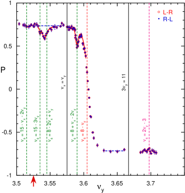
To test the data’s reproducibility, we tried to measure polarizations at the same settings several times. However, when we precisely measured the values after each setting, we found that the slow ramps were often not exactly identical at the level. Thus, Fig. 2 has many partly-overlapping points, which obscure the polarization’s behavior near each resonance. We tried to clarify Fig. 2 by combining points with nearby values, except in the regions where the polarization changed very rapidly (between values of 3.586 to 3.620). We first combined all pairs of points that had values within . To help ensure that this did not bias the results, we combined the data in both the increasing (Left-to-Right) and decreasing (Right-to-Left) directions; the two results were identical. We then sequentially increased the intervals in steps of ; the input data for each step were the output data from the previous step. The error and position of each newly combined point after each step were the properly weighted averages of the errors and positions of the two combined points; each new horizontal bar encompassed the slow ramps of both combined points.
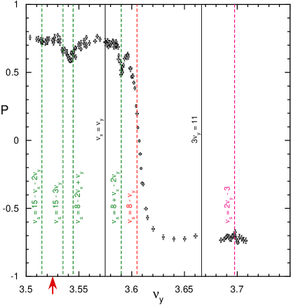
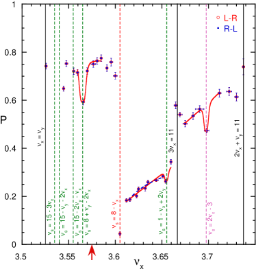
Figure 3 plots polarization vs. for the combination interval of . The 76 combination steps reduced the number of data points from 131 to 95. The plot shows clear resonance behavior around several 3rd order resonances, but the behavior around the 2nd order resonance is still unclear. When we further increased the combination interval size, the polarization’s behavior around the narrow resonances was broadened excessively, as expected.
We observed full spin-flip when the 1st order vertical () spin resonance was crossed; we also found partial depolarization near several 3rd order resonances and possibly near a 2nd order resonance. The 3rd order resonance and the partly overlapping 3rd order and resonances appear significantly stronger than the 2nd order resonance. This suggests that many significant 3rd and possibly higher order spin resonances must be overcome to accelerate and store polarized protons above 100 GeV.
We also studied the higher order horizontal () spin resonances by using ramps similar to the ramps in Fig. 1, with fixed at . We first rapidly ramped from to a value between in 0.5 s; we next slowly ramped through a range of about in 2 s; then we measured the polarization. The rapid ramp again reduced the effects of the resonances between the injection tune of and the start of the slow ramp, while each slow tune ramp enhanced the effect of the resonance in that small range.
The polarizations are plotted in Fig. 4 against . The 5 pairs of overlapping points were combined, as earlier described for Fig. 3. Figure 4 shows almost full depolarization at the 1st order spin resonance. Above this resonance, the polarization increased steadily probably because this fairly strong resonance was crossed at increasing rates, which decreased the depolarization stora ; increased because the ramp time was fixed at 0.5 s, while the ramp range was increased. Thus, we found partial depolarization near a 2nd order resonance and near several 3rd order resonances; these resonances all seem about equally strong. Recall that some 3rd order resonances seem significantly stronger than the 2nd order resonance.
Also note that the polarization increased significantly at the two beam-blow-up resonances probably because they removed mostly those beam particles with larger betatron amplitudes, as supported by the sharp decrease in the precisely measured count rates in EDDA at each blow-up resonance. These outside particles were probably more depolarized ratner when crossing the strong 1st order spin resonance; thus, removing them increased the beam’s polarization while decreasing its intensity.
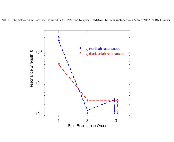
The measured strengths of the 11 resonances, for which we had adequate data, are listed in Table 1. We first obtained the very strong 1st order resonance’s and , respectively from the left and right horizontal dashed line fits in Fig. 3. We then obtained its strength using the measured and the fast ramp’s time of 0.5 s and of 0.105 in the Froissart-Stora equation stora :
| (2) |
We could only set a lower limit on of because the 1st order resonance was so strong that the spin was fully flipped for our fixed of 0.5 s. For the strong 1st order resonance, the blue dashed curve in Fig. 4 is the fit of Eq. (2) to the 8 data points just after crossing it, using of 0.5 s and equal to each point’s from the value at injection.
For each isolated 2nd and 3rd order resonance, we obtained its dip’s depth or polarization loss () by using a minimization fit of a 2nd order Lorentzian to that resonance s data with a base-line obtained from its nearby points. The () values of the two overlapping 3rd order resonances in Fig. 3 were obtained by a fit using two overlapping Lorentzians and the baseline shown by the horizontal dashed blue line. We simultaneously fit the stronger (8 - 2 + ) resonance to a 1st order Lorentzian, with its frequency a variable in the fit, and the weaker (15 - 3) resonance to a 2nd order Lorentzian with its frequency held fixed at the calculated value shown by its dashed green line. The fits to all 2nd and 3rd order resonances are shown by the solid red curves in Figs. 3 and 4. Three 2nd and 3rd order resonances had no observable dip at their calculated or value; therefore, the lower limits on their were taken to be 95%, which was 4 times the average error on straight line fits to the data points near these apparently weak resonances. We then phenomenologically used () in Eq. (2) with our fixed experimental of 2 s and of 0.002 to obtain for each 2nd and order resonance.
| Type | Order | Resonance | ||
| F-S eq. fit | ||||
| inadequate data | ||||
| inadequate data | ||||
There were several theoretical attempts Tepikian ; Mane ; Hoffstaetter to calculate the strengths of higher order spin resonances; one Tepikian suggests that odd order resonances may be stronger than even order resonances for rings with Siberian snakes. It is not yet clear if these theoretical approaches allow one to explain our experimental results.
In summary, we used 2.1 GeV/ polarized protons stored in the COSY synchrotron to study 1st and higher order spin resonances. We observed almost full spin-flip when the 1st order spin resonance was crossed and partial depolarization near the 2nd and 3rd order spin resonances. We also observed almost full depolarization near the 1st order spin resonance and partial depolarization near the 2nd and 3rd order spin resonances. It was thought that, for vertically polarized protons in flat accelerators, vertical spin resonances are stronger than horizontal resonances, and lower order resonances are stronger than higher order resonances. The data suggest that many higher order spin resonances, both horizontal and vertical, must be overcome to accelerate polarized protons to high energies; these data may help RHIC to better overcome its snake resonances between 100 and 250 GeV/.
We thank COSY’s staff for a successful run. We thank E.D. Courant, Ya.S. Derbenev, D. Eversheim, R. Gebel, A. Lehrach, B. Lorentz, R. Maier, Yu.F. Orlov, D. Prasuhn, H. Rohdjeß, T. Roser, H. Sato, A. Schnase, W. Scobel, E.J. Stephenson, H. Stockhorst, K. Ulbrich and K. Yonehara for help and advice. The work was supported by grants from the German BMBF Science Ministry and its JCHP-FFE program at COSY.
References
- (1) D.G. Crabb et al., Phys. Rev. Lett. 41, 1257 (1978).
- (2) Proc. SPIN 2000, AIP Conf. Proc. 570 (AIP, NY, 2001).
- (3) Proc. SPIN 2002, AIP Conf. Proc. 675 (AIP, NY, 2003).
- (4) Proc. SPIN 2004, eds. K. Aulenbacher et al. (World Scientific, Singapore, 2005).
- (5) Proc. SPIN 2006, AIP Conf. Proc. 915 (AIP, NY, 2007).
- (6) Proc. SPIN 2008, AIP Conf. Proc. 1149 (AIP, NY, 2009).
- (7) R.D. Ruth et al., AIP Conf. Proc. 145, 62 (AIP, NY, 1986).
- (8) V.A. Anferov et al., Acceleration of Polarized Protons at Fermilab, Report UM HE 95-09 (July 24, 1995), p 127.
- (9) S. Tepikian, AIP Conf. Proc. 187, 1450 (AIP, NY, 1989).
- (10) S.R. Mane, ibid, p 959.
- (11) G.H. Hoffstaetter and M. Vogt, Phys. Rev. E 70, 056501 (2004).
- (12) J.R. Johnson et al., NIM 204, 261 (1983).
- (13) J.E. Goodwin et al., Phys. Rev. Lett. 64, 2779 (1990).
- (14) C. Ohmori et al., Phys. Rev. Lett. 75, 1931 (1995).
- (15) A.D. Krisch et al., Ref 4, p 691.
- (16) M. Froissart and R. Stora, NIM 7, 297 (1960).
- (17) E.D. Courant, Bull. Am. Phys. Soc. 7, 33 (1962) and Rpt. BNL-EDC-45 (1962).
- (18) B.W. Montague, Phys. Rep. 113, 35 (1984).
- (19) S.Y. Lee, Spin Dynamics and Snakes in Synchrotrons, p 26 (World Scientific, Singapore, 1997).
- (20) R. Maier, NIM A 390, 1 (1997).
- (21) A. Lehrach et al., Ref 3, p 153.
- (22) V. Schwarz et al., Proc. SPIN 1998, eds. N.E. Tyurin et al., (World Scientific, Singapore, 1999), p 560.
- (23) M. Altmeier et al., Phys. Rev. Lett. 85, 1819 (2000).
- (24) H. Stein et al., At. Energ. 94, 24 (2003).
- (25) D. Chiladze et al., Phys. Rev. ST-AB 9, 050101 (2006).
- (26) P.D. Eversheim et al., AIP Conf. Proc. 339, 668 (AIP, NY, 1995).
- (27) R. Weidmann et al., Rev. Sci. Instrum. 67, 1357 (1996).
- (28) O. Felden et al., Proc. 9th Internat. WS Polar. Sources, Targets, 2001, eds. V.P. Derenchuk and B. von Przewoski (World Scientific, Singapore, 2002), p 200.
- (29) M.A. Leonova et al., Phys. Rev. Lett. 93, 224801 (2004).
- (30) L. G. Ratner et al., AIP Conf. Proc. 35, 396 (AIP, NY, 1976)[see p 403]; S.Y. Lee, Ref 19, p 58.