A simple scheme for quantum networks based on orbital angular momentum states of photons
Abstract
We propose a new quantum network scheme using orbital angular momentum states of photons to route the network and spin angular momentum states to encode the information. A four-user experimental scheme based on this efficient quantum network is analyzed in detail, which is particularly appealing for the free space quantum key distribution.Users can freely exchange quantum keys with each other.
keywords:
quantum network \seporbital angular momentum \sepspin angular momentum \PACS42.50Ct \sep42.60.Jf \sep03.67.HK, \corauth[cor]Correspondent author:fq_wang@163.com
1 Introduction
Quantum key distribution (QKD) network has recently attracted growing attention. In the past few years, researchers have proposed several outstanding QKD network schemes based on different mechanisms, such as the passive optical network (PON)[1], the silica-based planar lightwave circuit (PLC) non-blocking matrix switch[2], the wavelength division multiplexing (WDM)[3][4], and the multi-particle entanglement[5] etc. The passive optical network[1] opens a way for the development of quantum network, though it’s not a practical implementation since the network users have to share security information with a single controller. And the PLC matrix switch network[2] shows the possibility of sending quantum signals through current optical networks. Most recently, Wei.C and his colleagues[4] introduce a quantum router which processes network addresses through WDM. Anyway, the common feature of these schemes is that they aim to build a one-to-any QKD network or an any-to-any one through the conventional optical network. In this paper, we present a novel network mechanism using spin angular momentum (SAM) and orbital angular momentum (OAM) [6] states of photons, which is particularly appealing for the free space QKD. The angular momentum of photons can contain not only a spin contribution associated with the polarization, but also an orbital contribution arising from phase fronts that are inclined with respect to the beam’s propagation axis. Such screw beams have an azimuthal phase dependence of the form and carry a discrete OAM of units per photon along their propagation direction. The value is an integer and corresponds to the number of times the phase changes by in a closed loop around the beam. In 2004, it was reported that these OAM states can be used to transmit information [7]. Most recently, L.-P.Deng et al. have present two-optical CNOT gates using SAM and OAM of a single photon as qubits [8]. In our newly network scheme, the quantum information is encoded in SAM states of photons, and the network addressing is automatically processed according to OAM states. Users can directly exchange the quantum keys with any other without a controller.Since the Hilbert space spanned by OAM states is in principle infinite, the number of users in this network can be increasable, but one point we should note is that the number of channels depends on the size of every aperture[9].
The paper is organized as follows: in Section 2 we review the interferometric OAM sorters[10][11] which can distinguish the OAM states of single photons. Section 3 analyzes in detail an experimental network scheme based on the newly-proposed total angular momentum (TAM) sorter[12]. Section 4 gives a summary of the paper.
2 Interferometric OAM sorter
In this section, we will use matrix formulation[13][14] to depict the propagation property of photons with definite OAM through the previous interfermetric OAM sorters. Laguerre-Gaussian (LG) beams are examples of light beams with an intensity structure that is rotationally symmetric about the beam axis and a phase structure with an azimual dependence . Any LG modes of order N can be expanded as the sum of Hermite-Gaussian (HG) modes of the same order:
| (1) |
with the complete coefficients:
| (2) |
where , are arbitrary nonnegative integers, and is the order of the mode. Laguerre-Gaussian modes are characterized by two mode indices and , where is the number of cycles in phase around the circumference and is the number of radial nodes. It follows that such a mode can be represented by a column vector with elements:
| (3) |
To show how this -element column vector may be used, let’s consider the passage of the LG mode of order N through a beam rotator. The mode rotation matrices of a beam rotator are given in Refs.[13][14]. Take , for example, the mode passes through a beam rotator with rotation angle , the column vector describing the output beam is given by:
| (4) |
As we can see from Eq.(4) , the relative phase difference between the input and output beam is . Furthermore, when the LG mode with the azimuthal phase form passes through a rotator with angle , the phase shift between input and output mode is . Therefore, for particular combinations of and , the rotated beam may be either in or out of phase with respect to the original. If such a rotation is incorporated into the arms of a two-beam interferometer, then the phase shift between the two arms becomes dependent. Using the above concept, Leach etc. proposed a sorter for distinguishing the OAM of single photons[10]. It consists of cascading Mach-Zender interferometers with a Dove prism placed appropriately in each arm. A simple diagram of the first stage of this sorter is presented in Fig.1(a). The two Dove prisms, rotated with respect to each other through an angle , rotate a passing beam through an angle . In 2003 a simplification of the above approach was described [11]. Comparatively, the sketch of the latter approach is outlined in Fig.1(b). The phase difference introduced by the beam rotator is . The phase offset introduced by the phase delay plate is independent of . This device can sort individual photons according to their values, since the photons exit the interferometer through different output ports. Ref.[11] also pointed out a quite original idea that we can utilize the distinguishable OAM states as distinct channels. Such a scheme may be called mode-division multiplexing (MDM), in analogy with the traditional terminology WDM of optical communications.

3 OAM quantum network
After describing the feature of OAM sorter, we will discuss how to use OAM sorter to realize quantum network. Let’s first analyze the experimental network scheme based on the newly-proposed TAM sorter in this section. The TAM of a photon is given by the sum of SAM and OAM. In the network, we encode information in the SAM of photons and use distinguishable OAM states to process network addresses. Combining the interferometric OAM sorter[10] with proper polarization beam splitters (PBS) provides a way to sort photons on the basis of TAM. However, in general a Dove prism slightly changes the polarization state of a passing beam and therefore cannot be used for TAM sorting. For the sake of simultaneously measuring the SAM and OAM of single photons exactly, Leach etc. designed a prism that rotates both phase and intensity but acts as a quarter-wave plate on the polarization vector[12]. Under this excellent achievement, we devised a new scheme for QKD network. To illustrate our idea more clearly, we give an example of four-user QKD as shown in Fig.2.
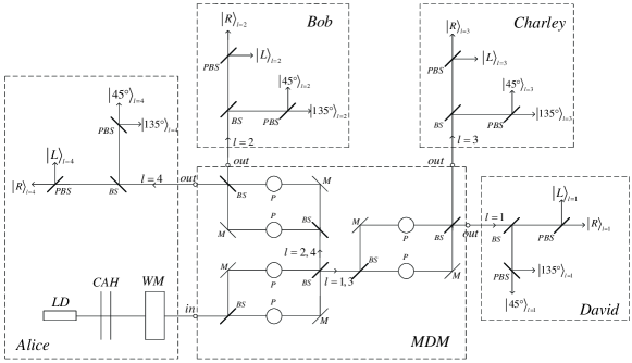
From Fig.2, we can see that Alice is connected to Bob, Charley and David by way of the MDM. When Alice wants to communication with Bob, Charley or David, she uses the fist diffraction order of a computer addressable hologram (CAH) to prepare photons of , or accordingly. These photons will be separated by the OAM sorters and transmitted to the appointed users according to the OAM states of photons.
In this scheme, photons are prepared in continuum of polarization states, for example, the two diagonal states, and , or the two circular states, and . When the photons pass through the MDM, their polarization states will be changed by the quarter-wave plates, which Jones matrix is , because the prisms used in the MDM act as a quarter-wave plate on the polarization vector.
Now we will discuss in detail what states the photon will be changed into under the action of the quarter-wave plates. Table 1 shows the acting of the quarter-wave plates on the polarization states. From the table, we can see that the states are always divided into two sets, diagonal states and circular states. The two diagonal states and can be distinguished by one measurement, while the two circular states and can be distinguished by another measurement. But if a diagonal measurement is performed on a circular photon, the photon will behave randomly, acting half the time like and half the time like , and all information about its circular polarization is lost. Similarly, a random result is obtained and all information is lost if a circular measurement is performed on a diagonal photon. Therefore, the traditional BB84 protocol [15] can be used among the users in this scheme.
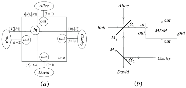
Based on the above OAM-QKD scheme, a quantum network, in which users can share private information with each other, will be designed easily. To illustrate the network more clearly, we take the four-user net for example, as shown in Fig.3(a). Alice, Bob, Charley, and David are connected by the MDM, whose addresses are , , and respectively. Any one, who wants to share information with Alice, for example, ought to prepare the photons in the OAM states. On the other hand, to make others know the signal photons are sent by Charley, Charley should sent two light pulses in right-handed, left-handed polarization respectively before sharing information. The receiver will perform the corresponding measurement on the fist two photons. It’s the similar communication procedure for other users. As one would expect, the MDM just helps to connect with two intended users, and the unconditional security in quantum communications will not change. Therefore, the usual point-to-point QKD protocols can be used by the users in the network. Fig.3(b) gives a possible way to put the photons sent by Alice, Bob, Charley and David into a single in-port. In Fig.3(b), M1 and M2 are two rotating mirrors controlled by a program logic control system. When Charley intends to transmit photons into the in-port, rotation angle of the two mirrors will be set and respectively. Similarly, the angle (,) is for David, (,) is for Bob, and (,) is for Alice. More generally, an intelligent system must be designed to change not only the rotation angle but also the positions of the two mirrors, since the incident light is not always from the same direction. We are ready to do some related work soon.
4 Discussion and Summary
Though the optical fiber is the main transmission medium for optical communication, it still requires to perform QKD through free space, since the satellite technology has been popularized nowadays. Besides, it is difficult to distribute the quantum key through more than 200 km with fiber due to the losses and the low single-photon detection efficiency. And free-space QKD is now attracting increasing attention[16-18] because of its low-transmission loss. It is a good idea to implement our network scheme among the relay stations like the moving satellites. For one thing, the OAM states are invariant under rotations about the propagation direction, making this implementation independent of the alignment between the reference frames of the sender and receiver, and hence appealing for free space QKD[19]. For another, the essentially nonbirefringe nature of the atmosphere at optical wavelengths allows the faithful transmission of the single photon polarization states used in our network scheme. Therefore, our scheme is worthy to be studied further.
However, there are challenges to implement our scheme in free space QKD. First, the atmospheric turbulence will destroy the vortex structure of LG modes even for weak turbulence[20]. Second, before applying our newly-proposed scheme to a large scale QKD network, we should find out a practical way to put more separated lights into a single beam line. Third, the problems of general free space QKD, such as beam wander and background photon counts, will present to our scheme also. The three difficulties mentioned above will become quite meaningful subjects in scientific research about free space QKD. As to the first problem, the distortions created by atmospheric turbulence on OAM photon states[20] could be corrected using two-dimensinal filtering techniques that have been proposed for image recovering under various degradation mechanisms[21]. Regarding the second question, we are pleased to see that it opens up a whole new topic for all scientists, and we are preparing to do some related research next. As for the third point, researchers have put forward a series of possible ways, including narrow filters[22][23], spatial filtering[24], and adaptive optics[25], to render the transmission and detection problems over these years. With the above interesting problems, the pace of scientific research will not stop.
In conclusion, we have devised a novel network scheme based on OAM and SAM of photons, which is particularly appealing for the free space QKD. We also describe a four-user experimental scheme of this efficient quantum network in detail. Users in this network can freely exchange information with each other.
5 Acknowledgements
This work is supported by the State Key Development Program for Basic Research of China (Grant No.2007CB307001).
References
- [1] P.D. Townsend, Nature, 385(1997) 47.
- [2] T.Honjo, K.Inoue, A.Sahara, E.Yamazaki, H.Takahashi, Optics Comm. 263(2006) 120.
- [3] P.D.Kumavor, A.C.Beal, E.Donker, B.C.Wang, J. of Light. Tech. 24(2006) 3103.
- [4] W.Chen, Z.-F.Han, T.Zhang, H.Wen, Z.-Q.Yin, F.-X.Xu, Q.-L.Wu, Y.Liu, Y.Zhang, X.-F.Mo, Y.-Z.Gui, G.Wei, G.-C.Guo,Field Experimental “Star Type” Metropolitan Quantum Key Distribution Network, in Submission
- [5] F.-G. Deng, X.-S.Liu, Y.-J.Ma, L.Xiao, G.-L.Long, Chin. Phys. Lett. 19(2002) 893.
- [6] G.F.Calvo, A.Picon, E.Bagan,Phys.Rev.A,73(2006)013805.
- [7] G.Gibson, J.Courtial, M.J.Padgett, Optics Express,12(2004)5448.
- [8] L.-P.Deng, H.B.Wang, K.Wang, J.Opt.Soc.Am.B,24(2007)2517.
- [9] D.A.B.Miller, Optics Express,23(1998)1645.
- [10] J.Leach, M.J.Padgett, S.M.Barnett, S.F.-Arnold, J.Courtial, Phys.Rev.Lett. 88(2002)257901.
- [11] H.Q.Wei, X.Xue, J.Leach ,M.J.Padgett, S.M.Barnett, S.F.-Arnold, E.Yao, J.Courtial, Optics Comm. 223(2003) 117.
- [12] J.Leach, J.Courtial, K.Skeldon, S.M.Barnett, S.F.-Arnold, M.J.Padgett, Phys.Rev.Lett.92(2004)013601.
- [13] L.Allen, J.Courtial, M.J.Padgett, Phys.Rev.E,60(1999)7497.
- [14] A.T.O’Neil, J.Courtial, Optics comm. 181(2000)35.
- [15] C.H.Bennett, G.Brassard, Proceedings of IEEE International Conference on Computers, Systems and IEEE, IEEE, New York, 1984, p.175.
- [16] W.T.Buttler,R.J.Hughes, P.G.Kwiat, S.K.Lamoreaux, G.G.Luther, G.L.Morgan, J.E.Nordholt, C.G.Peterson, C.M.Simmons, Phys.Rev.Lett.81 (1998)3283.
- [17] W.T.Buttler, R.J.Hughes, S.K.Lamoreaux, G.L.Morgan, J.E.Nordholt, C.G.Peterson, Phys.Rev.Lett.84(2000)5652.
- [18] Q.-L.Wu, Z.-F.Han, E.-L.Miao, Y.Liu, Y.-M.Dai, G.-C.Guo, Optics Comm. 275(2007) 486.
- [19] F.M.Spedalieri, Optics Comm. 260(2006) 340.
- [20] C.Paterson, Phys.Rev.Lett.94(2005)153901.
- [21] S.I.Sadhar, A.N.Rajagopalan, J.Opt.Soc.Am.A, 22(2005)604.
- [22] J.G.Walker, S.F.Seward, J.G.Rarity, P.R.Tapster,Quantum Opt. 1(1989)75.
- [23] S.F.Seward, P.R.Tapster, J.G.Walker, J.G.Rarity, Quantum Opt. 3(1991)201
- [24] W.T.Buttler, R.J.Hughes, P.G.Kwiat, G.G.Luther, G.L.Morgan, J.E.Nordholt, C.G.Peterson, C.M.Simmons, Phys.Rev.A 57(1998) 2379.
- [25] C.A.Primmerman, D.V.Murphy, D.A.Page, B.G.Zollars, H.T.Barclay, Nature (London) 353(1991) 141.