Major physical characteristics of Rochelle salt:
the role of
thermal strains
Abstract
We compare the results for the related to the shear strain physical characteristics of Rochelle salt obtained within the recently developed modified two-sublattice Mitsui model that takes into account the strain and the diagonal components of the strain tensor , , with the results of the previous modification of the Mitsui model with the strain only. Within the framework of the model with the diagonal (thermal expansion) strains, we also reexamine the effects of the longitudinal electric field on the dielectric properties of Rochelle salt.
Key words: Rochelle salt, thermal expansion, Mitsui model, strains, bias field
PACS: 65.40.De, 77.65.Bn, 77.22.Gm, 77.22.Ch
Abstract
У статтi порiвнюються результати для пов’язаних зi зсувною деформацiєю фiзичних характеристик сегнетової солi, отриманих в рамках нещодавно розвиненої модифiкованої двопiдґраткової моделi Мiцуї, що враховує деформацiю та дiагональнi компоненти тензора деформацiй , , , з результатами попередньої модифiкацiї моделi Мiцуї, що враховує лише . В рамках моделi з дiагональними (тепловими) деформацiями дослiджено вплив поздовжнього електричного поля на дiелектричнi властивостi сеґнетової солi.
Ключовi слова: сеґнетова сiль, теплове розширення, модель Мiцуї, деформацiї, електричне поле
PACS: 65.40.De, 77.65.Bn, 77.22.Gm, 77.22.Ch
1 Introduction
Rochelle salt is the first known ferroelectric and a curious material, undergoing two second-order phase transitions at K and K, with the intermediate ferroelectric phase. Spontaneous polarization is directed along the axis and accompanied by spontaneous shear strain in the plane.
Microscopic theories of Rochelle salt are usually based on the two-sublattice Mitsui model [1], which considers motion of certain ordering units in two interpenetrating sublattices of asymmetric double-well potentials. Deformational effects have to be included into the Mitsui model to get a proper description of Rochelle salt behavior. Thus, only with taking into account the piezoelectric coupling with [2] it yields the qualitatively correct behavior of the relaxation time and dynamic dielectric permittivity near the Curie temperatures. The same modification of the Mitsui model also provides a fair description of the major dielectric, piezoelectric, and elastic characteristics of Rochelle salt associated with the strain [2], although some systematic discrepancies between the theory and experiment do take place.
Recently, a further modification of the Mitsui model has been proposed [3] in order to consistently describe a number of effects associated with the diagonal components of the lattice strain tensor (). Along with the shear strain included into the Mitsui model in [2], this modification takes into account the diagonal strains in the manner suggested in [4] as well as the host lattice contribution into the energy of thermal expansion. It has been shown [3] to be efficient in describing the effect of hydrostatic, uniaxial, or biaxial pressure applied along the orthorhombic crystallographic axes of the crystal, its thermal expansion, as well as related to the diagonal strains components of piezoelectric (e.g. , ) and elastic () tensors, appearing in the ferroelectric phase only due to the lowered crystal symmetry.
In the present paper we shall explore how the inclusion of thermal strains affect the agreement with experiment for the physical characteristics of Rochelle salt related to the shear strain .
It has been also shown [5] that to correctly describe the dependences of the static dielectric permittivity of Rochelle salt on the longitudinal electric field at temperatures near (within the modified Mitsui model without the diagonal strains [2]), one has to assume that the external field is partially screened out due to the space-charge build-up at blocking electrodes. We shall verify whether this assumption is necessary for the model with the diagonal (thermal) strains [3].
2 -strain associated physical characteristics in presence
of diagonal strains
The expressions for thermodynamic potential, polarization and strains, as well as for the observable physical characteristics – second derivatives of thermodynamic potential, obtained within the Mitsui model with the diagonal strains, can be found elsewhere [3]. In the present paper we shall be interested only in the major characteristics, associated with polarization and shear strain . Those will be compared with the results obtained within the Mitsui model without diagonal strains [2].
The characteristics we are interested in are spontaneous polarization and strain , dielectric susceptibility of a clamped crystal , and the elastic constant at a constant field , the expressions for which are not modified by the inclusion of diagonal strains, except for renormalization of the model parameters (see [2] and [3]). On the other hand, the static dielectric susceptibility of a mechanically free crystal [3, 4] and the piezoelectric constant
| (1) |
contain new terms (the last sum), describing the contribution of the diagonal strains. Here are monoclinic piezoelectric coefficients different from zero only at non-zero polarization; is the matrix of elastic compliances, inverse to the matrix of elastic constants , the microscopic expressions for which, as well as the notations introduced above, have been presented earlier [3]. In the paraelectric phases the expressions for free susceptibility and coincide with those obtained within the modified Mitsui model without thermal strains [6].
The dynamics of Rochelle salt in the presence of diagonal strains is explored [7] elsewhere. The dynamic dielectric permittivity of a clamped crystal relevant to the present consideration is not explicitly dependent on the strains, apart from renormalization of the interaction constants. The expression for it is the same as in the model without thermal strains [2, 6]
| (2) |
where is the parameter setting the time scale of the dynamic processes in the pseudospin subsystem within the Glauber approach; the other notations are given in [6].
3 Numerical calculations
3.1 Model parameters
The values of the parameters of the model with diagonal strains were chosen [3] to provide as good as possible fit of the theory to the experimental data for the following characteristics of Rochelle salt: the Curie temperatures at ambient pressure () and their hydrostatic and uniaxial pressure slopes, the temperature curves of thermal expansion strains , linear thermal expansion coefficients, monoclinic piezoelectric coefficients, and elastic constants and (). The adopted values of the model parameters and the details of the fitting procedure have been given elsewhere [3].
Additionally, we need to determine the value of the parameter that sets the time scale of the model pseudospin dynamics. In earlier calculations [2] it was taken to be temperature independent s. However, the analysis [8] of the temperature dependences of the relaxation time and of the low-frequency limit of the clamped dynamic permittivity (measured at 155 MHz, just above the resonances, the experimental analog of the static clamped permittivity ) revealed that is proportional to and to , with . In terms of our model, it means that we should take to be temperature dependent. The best results are obtained at with s.
The adopted set of the model parameters is not unique; there are many other sets providing the fit to experimental data with the same error. Therefore, it is not possible to precisely establish the temperature variation of the interaction constants. However, the overall tendency is such that an increasing temperature decreases the asymmetry parameter and the constants of interactions between the pseudospins within the same and in different sublattices and . In other words, increasing temperature has the effect opposite to hydrostatic compression [3], which is understandable. The corresponding temperature slopes at the adopted values of the model parameters are K-1, K-1, and K-1.
The number and (if any) temperature and order of the phase transitions for the Mitsui model without thermal strains are usually analyzed in terms of dimensionless variables and
| (3) |
Here, is the parameter describing the coupling between the pseudospin subsystem and the shear strain [2]. The phase diagram of the conventional (undeformable) Mitsui model in the plane [9, 10, 11] shows the regions with different numbers and types of phase transitions; its topology does not change by inclusion of the shear strain .
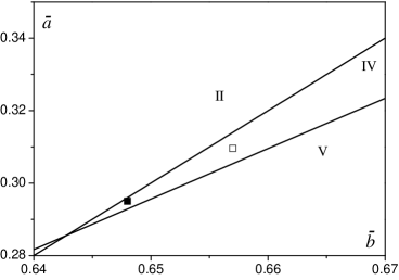
It has been found that only in a very narrow region of the plane, the system undergoes two second order phase transitions with the intermediate ferroelectric phase; this region (IV) is shown in figure 1. In the region V, the system undergoes no phase transition, whereas in the region II the system undergoes two second order phase transitions with the intermediate ferroelectric phase and below them — an additional first order phase transition to another ferroelectric phase, which persists down to 0 K.
The situation drastically changes in presence of diagonal strains, when and become functions of temperature and pressure. Here, the number and type(s) of phase transitions are governed by more than 10 model parameters with arbitrary (physically reasonable) values. At such circumstances we think it is impossible to construct a 2D or 3D phase diagram of the model, which would fully describe all the types of the temperature behavior and phase transitions in the system.
In the fitting procedure we deal with the values of and at the upper Curie temperature and ambient pressure and . The used values of and are from the region IV of the phase diagram of the undeformable Mitsui model. The points (, corresponding to the parameters of [2] and (, for the parameters of [3] are shown in figure 1.
With decreasing , the maximal values of the order parameter and spontaneous strain increase. In the previous model [2] we had to choose, in fact, the point almost on the boundary of the region IV, providing the maximal possible values of and in the middle of the ferroelectric phase. Nevertheless, the calculated spontaneous polarization and spontaneous strain were still appreciably smaller than the experimental ones. Interestingly, at the same values of for the model [3] and for the model [2], the maximal value of the order parameter obtained within the model with the thermal strains is much larger. Thus, at the adopted values of the fitting parameters it is , to be compared to 0.128 in [2].
3.2 -strain-related characteristics: role of diagonal strains
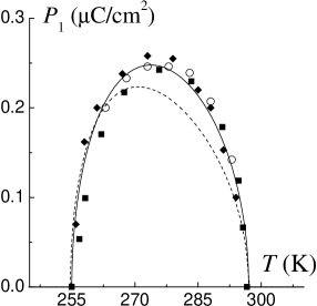
Figures 2 show that the modified Mitsui model with thermal strains [3] yields a notably larger values of the spontaneous polarization and spontaneous strain in the middle of the ferroelectric phase and a better agreement with experimental data. The obtained improvement is explained by the increased values of the order parameter in the center of a ferroelectric phase.

The role of diagonal strains is not so apparent for the other physical characteristics of Rochelle salt related to the shear strain . In particular this concerns the static dielectric permittivities of the free and clamped crystals, as well as the dynamic permittivity. Here, the differences between the obtained results, with one exception, are caused by a different route, taken in [3] at selecting the values of the parameters and . The same route could be taken within the previous modification of the Mitsui model.
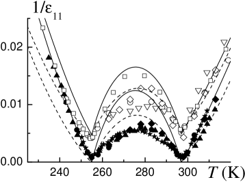
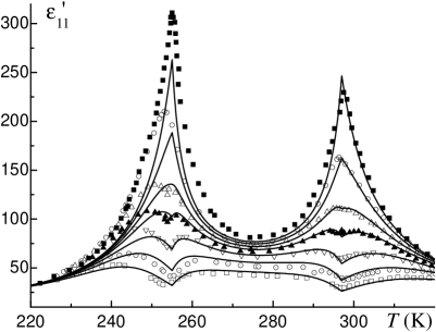
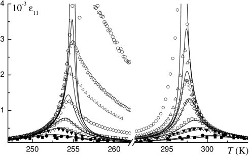
In the previous work [2] we were not able to simultaneously fit the free and clamped dielectric permittivities in the lower paraelectric phase with the same values of the dipole moment (the dashed lines in figure 3). It was chosen to provide the best fit for the dynamic dielectric permittivity [8] at microwave frequencies and for the static clamped permittivity at temperatures just below . Thence, the agreement with experiment for the free permittivity at these temperatures was unsatisfactory. Moreover, at even lower temperatures (below 240 K) the fit for the dynamic permittivity was also bad. In the upper paraelectric phase both free and clamped permittivities were well described.
The problem persists after the inclusion of diagonal strains. However, now we choose the dipole moment to provide the best fit for the free static permittivity in both paraelectric phases and for the dynamic dielectric permittivity [8] below 240 K. As a result, the agreement with experiment for the static clamped permittivity just below is spoiled. This is illustrated in figure 3.
In the ferroelectric phase, there is a considerable inconsistency between the two theories and experiment. This is attributed to the domain wall contributions into the static free permittivity that are not taken into account by either modification of the Mitsui model.
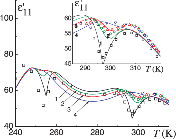
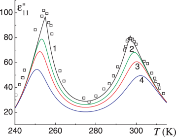
The temperature dependences of the real and imaginary parts of the dynamic dielectric permittivity of Rochelle salt calculated within the modifications of the Mitsui model with [3] and without [2] thermal strains are shown in figures 4 and 5.
Both models provide an excellent agreement with experimental data [8] for in the upper paraelectric phase. For , the newest results of the model [3] are slightly better, especially for very high frequencies (above 9 GHz).
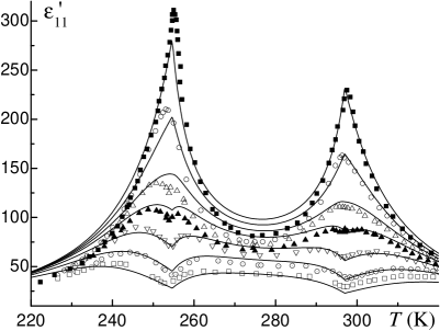

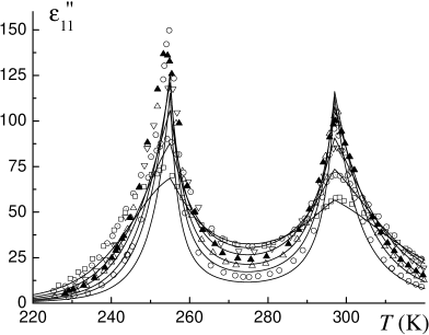
The domain effects are switched off at microwave frequencies. Therefore, they cannot explain the disagreement between the theory and experiment in the ferroelectric phase for and , which took place in the previous modification of the Mitsui model [2]. Inclusion of thermal strains allowed us to basically solve this problem; the obtained fit using this model is quite satisfactory in the ferroelectric phase. This improvement has the same origin as that for spontaneous polarization and spontaneous strain: the increased maximum value of the order parameter . This is the only exception when the improvement for the permittivities could not be obtained by changing the fitting procedure for and without taking into account the diagonal strains.
None of the models can properly describe the temperature variation of or below . As we have already mentioned, depending on the choice of we can obtain a good fit for either between 240 and 255 K (as was done in [2]) or below 230 K (in the model with diagonal strains). The agreement with experiment for is only qualitatively correct at all temperatures below ; quantitatively it is poor for both models.
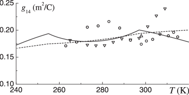
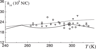
Comparison of the piezoelectric coefficients and calculated within the models [3] and [2] is given in figure 6. It can be seen that the agreement with experiment in the lower paraelectric phase for and in the upper paraelectric phase for obtained within the model with the thermal strains is better.
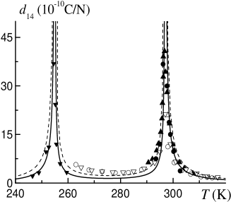
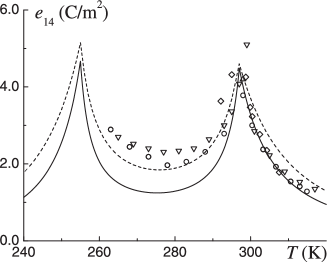
Inclusion of diagonal strains enhances the temperature dependence of the piezoelectric constants and , as seen in figure 7. The theoretical curves, however, are still within the dispersion range of the experimental data. This is the only case when we could see that the diagonal strains being taken into account produced some qualitative changes in the calculated characteristics related to the strain .
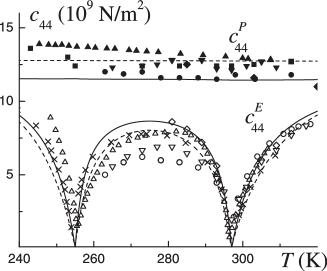
No direct effect of diagonal strains on the elastic constants related to the shear strain is evident. Due to the different value of the ‘‘seed’’ elastic constant we were able to improve the agreement with experiment for the elastic constant at a constant field in the lower paraelectric phase. The fit for the elastic constant at a constant polarization becomes a little worse, though the theoretical curve does not fall out of the dispersion range of the experimental data.
It should be mentioned that the agreement with experiment for the free static permittivity (figure 3), piezoelectric coefficient (figure 6), and elastic constant (figure 8) in the ferroelectric phase is getting even worse when the diagonal strains are taken into account. The disagreement, however, is obviously caused by the domain-wall motion contributions into the mentioned characteristics, which are not taken into account within the present [3] or previous [2] versions of the Mitsui model. On the other hand, the dynamic dielectric permittivity at microwave frequencies (figures 4, 5) and the free static permittivity in high bias fields (above at least 0.5 kV/cm, see next subsection), when the domain contributions are switched off, are very well described by the Mitsui model with the diagonal strains.
3.3 Longitudinal electric field effects
The longitudinal electric field directed along the axis of spontaneous polarization, being the field conjugate to the order parameter, smears out the phase transitions, decreases the maximal values of permittivity , and shifts the upper maximum temperature upward and the lower maximum temperature downward. The phenomenological Landau-Devonshire formalism presumes that and the shifts of permittivity maxima temperatures are expected to vary with the external field as [28].
Those dependences are obtained starting with the simplified Landau expansion of the thermodynamic potential (elastic and piezoelectric contributions not considered)
| (4) |
From (4), the equations for polarization and inverse permittivity follow
| (5) |
In the case of Rochelle salt, the expansion (4) can be performed near each of the two transitions separately, assuming a linear temperature dependence for the lower transition and for the upper one. Then, the field dependences of and can be presented as [28]:
| (6) |
| (7) |
The previous calculations [5] of the bias field dependences of the static free permittivity of Rochelle salt performed within the model without the diagonal strains [3] have shown that the theory, though being qualitatively correct, strongly overestimates the field effect on temperature and magnitude of the upper permittivity maximum. In fact, the calculated curves in the vicinity of coincided with the experimental points obtained in much lower fields. On the other hand, the theory accorded well with experiment in the vicinity of the lower Curie temperature.
To correctly describe the field dependences of the static dielectric permittivity of Rochelle salt at temperatures near , we had to use in our calculations the effective field at , instead of the values of the actually applied in the experiments field , whereas below . An assumption has been made that the external field is partially screened out due to the space-charge build-up at blocking electrodes [5].
The calculations performed within the modified Mitsui model with the thermal strains [3] show that this assumption may be incorrect. Indeed, as seen in figures 9 and 10, no overestimation of the field effects on the temperature curves of the static free permittivity is obtained. In fact, the experimental permittivity maxima are almost always lower than the theoretical ones. The field dependences of the temperature shifts of the maxima are rather well described by the theory. The theoretical and vary with the external field as , in agreement with the Landau theory.
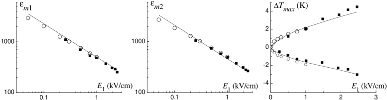
We can now deduce the values of the coefficients of the Landau expansion. The theoretical curves in figure 10 are well approximated by (6) and (7) dependences with
yielding
Figure 11 illustrates the field effects on the microwave dynamic dielectric permittivity of Rochelle salt. The theoretical curves were calculated within the model with the thermal strains. In zero field, the real part of the permittivity at 8.25 GHz has shallow minima at the transition points and a pair of rounded maxima at both sides of each minimum [8]. Application of d.c. bias smears out the minima, which shift toward the corresponding paraelectric phases, and each pair of maxima tends to coalesce. At sufficiently high fields, the maxima merge, and the minima disappear. At temperatures far from the transition regions, the real part of the permittivity only decreases with the bias field. This behavior is illustrated in figure 11, and it accords qualitatively with the experimental results of [8]. The behavior of the imaginary part of the permittivity is qualitatively the same as that of the static permittivity: it decreases with the field at all temperatures.
4 Concluding remarks
In the present paper we compare the results obtained within two modifications ([2] and [3]) of the two-sublattice Mitsui model for physical characteristics of Rochelle salt associated with the shear strain . The role of diagonal strains in the mentioned characteristics is explored.
It is shown that the thermal strains being taken into account bring about mostly quantitative changes in the calculated -strain-related characteristics. The only qualitative effect is the enhancement of the temperature variation of the piezoelectric constants and .
The agreement with experiment for spontaneous polarization, spontaneous strain , and dynamic dielectric permittivity in the ferroelectric phase, is significantly improved, as compared to that of the modified Mitsui model without diagonal strains [2]. The obtained improvement comes not from direct contributions into these characteristics of diagonal strains, but from the fact that the extended model yields larger values of the order parameter , resulting in a better fit to the experiment.
For the elastic constants and dielectric permittivities in the paraelectric phases, the inclusion of diagonal strains did not result in any apparent quantitative changes. We, however, adopted a slightly different route during the fitting procedure for the parameters , , and , which allowed us to somewhat improve the agreement with experiment. The same route can be taken within the model without diagonal strains as well.
It has been also shown previously [3] that the model with diagonal strains yields a better agreement with experimental data for small anomalies of specific heat of Rochelle salt at the Curie points than it was obtained with the earlier model [2], especially for the magnitude of the upper anomaly. In this case, in contrast to the above discussed cases of spontaneous polarization and spontaneous strain, the obtained improvement is caused by taking into account the explicit contributions of diagonal strains.
We also reexamine the effect of the longitudinal bias field on the dielectric characteristics of Rochelle salt. The model with thermal strains yields a fair agreement with experiment; its results also accord with the prediction of the Landau-Devonshire theory. In contrast to the calculations within the model without thermal strains [5], there is no need to assume that the external electric field is screened out by the space charge buildup at the blocking electrodes.
References
- [1] Mitsui T., Phys. Rev., 1958, 111, 1259; doi:10.1103/PhysRev.111.1259.
-
[2]
Levitskii R.R., Zachek I.R., Verkholyak T.M., Moina A.P., Phys.
Rev. B., 2003, 67, 174112;
doi:10.1103/PhysRevB.67.174112. - [3] Moina A.P., Levitskii R.R., Zachek I.R., Condens. Matter Phys., 2011, 14, 43602; doi:10.5488/CMP.14.43602.
- [4] Levitskii R.R., Zachek I.R., Moina A.P., Condens. Matter Phys., 2005, 8, 881.
- [5] Moina A.P., Slivka A.G., Kedyulich V.M., Phys. Status Solidi B, 2007, 244, 2641; doi:10.1002/pssb.200541436.
- [6] Moina A.P., Levitskii R.R., Zachek I.R., Phys. Rev. B, 2005, 71, 134108; doi:10.1103/PhysRevB.71.134108.
- [7] Moina A.P. Preprint arXiv: cond-mat.mtrl-sci/1201.3482, 2012.
- [8] Sandy F., Jones R.V., Phys. Rev., 1968, 168, 481; doi:10.1103/PhysRev.168.481.
- [9] Vaks V.G. Introduction into Microscopic Theory of Ferroelectrics. Nauka, Moscow, 1973 (in Russian).
- [10] Levitskii R.R., Verkholyak T.M., Kutny I.V., Hil I.G. Preprint arXiv: cond-mat/0106351, 2001.
- [11] Dublenych Yu.I., Condens. Matter Phys., 2011, 14, 23603; doi:10.5488/CMP.14.23603.
- [12] Cady W.G. Piezoelectricity: an Introduction to the Theory and Application of Electromechanical Phenomena in Crystals. McGraw Hill Book Company, Inc., New York, London, 1946.
- [13] Hablützel J., Helv. Phys. Acta, 1939, 12, 489.
- [14] Mueller H., Phys. Rev., 1935, 47, 175; doi:10.1103/PhysRev.47.175.
- [15] Ubbelohde A.R., Woodward I., Proc. R. Soc. Lond. A 5, 1946, 185, 448; doi:10.1098/rspa.1946.0030.
-
[16]
Schneider U., Lunkenheimer P., Hemberger J., Loidl A.,
Ferroelectrics, 2000, 242, 71;
doi:10.1080/00150190008228404 - [17] Taylor W., Lockwood D.J., Labbe H.J., J. Phys. C: Solid State Phys., 1984, 17, 3685; doi:10.1088/0022-3719/17/20/017.
- [18] Mason W.P., Phys. Rev., 1939, 55, 775; doi:10.1103/PhysRev.55.775.
- [19] Mason W.P., Phys. Rev., 1947, 72, 854; doi:10.1103/PhysRev.72.854.
- [20] Gutin L., Zh. Eksp. Teor. Fiz., 1945, 15, 199 (in Russian).
- [21] Silvestrova I.M., Yurin V.A., Shuvalov L.A., Podlesskaya A.V., Bull. Acad. Sci. USSR, Phys. Ser., 1965, 29, 2005.
- [22] Beige H., Kühnel A., Phys. Status Solidi A, 1984, 84, 433; doi:10.1002/pssa.2210840211.
- [23] Lichtenstein R., Phys. Rev., 1947, 72, 492; doi:10.1103/PhysRev.72.492.
- [24] Mason W.P. Piezoelectric Crystals and Their Application to Ultrasonics. New York, Van Nostrand, 1950.
- [25] Serdobolskaya O.Yu., Fiz. Tverd. Tela, 1996, 38, 1529.
- [26] Berlincourt D.A., Curran D.R., Jaffe H. — In: Physical Acoustics, Vol. 1, Part A, pp. 169–270, edited by W.P. Mason. Academic Press, New York, 1964.
- [27] Price W.J., Phys. Rev., 1949, 75, 946; doi:10.1103/PhysRev.75.946.
- [28] Lines M.E., Glass A.M. Principles and Application of Ferroelectrics and Related Materials. Clarendon Press, Oxford, 2001.
- [29] Slivka A.G., Kedyulich V.M., Levitskii R.R., Moina A.P., Romanyuk M.O., Guivan A.M., Condens. Matter Phys., 2005, 8, 623.
- [30] Akishige Y., Kamishina Y., J. Phys. Soc. Jpn., 1992, 61, 4589; doi:10.1143/JPSJ.61.4589.
Ukrainian \adddialect\l@ukrainian0 \l@ukrainian
Основнi фiзичнi характеристики сеґнетової солi: вплив теплових деформацiй А.П. Моїна
Iнститут фiзики конденсованих систем НАН України, вул. Свєнцiцького, 1, 79011 Львiв