Localized surface plasmon modes in a system of two interacting metallic cylinders
Abstract
We study an optical response of a system of two parallel close metallic cylinders having nanoscale dimensions. Surface plasmon excitation in the gap between the cylinders are specifically analyzed. In particular, resonance frequencies and field enhancement were investigated as functions of geometrical characteristics of the system and Ohmic losses in the metal. The results of numerical simulations were systematically compared with the analytical theory, obtained in the quasi-static limit. The analytical method was generalized in order to take into account the retardation effects. We also present the physical qualitative picture of the plasmon modes, which is validated by numerical simulations and analytical theory.
I Introduction
Localized surface plasmon excitations in metal-dielectric systems of subwavelength size is a topic under intensive study during the last decade. Fabrication techniques of wire-grid polarizers Suzuki2010 ; Ekinci2006 , nano-antennas Berthelot2009 ; Bakker2008 ; Lakowicz2007 ; Bloemendal2006 ; Jain2007 , and arrays of metallic particles Zhou2010 ; Sanders2006 ; Maier2003 are rapidly improving. Optical properties of aggregates of metallic grains are very different from those of the separate grains. Field refraction by such systems possesses typical features, in particular a strong field enhancement in the gaps between closely located metallic particles leading to an increase of scattering and absorption in comparison with those for single grains. The resonance frequency of surface plasmons in the systems depends both on particle sizes and inter-particle distances. It is red-shifted for modes with electric field polarization directed across the gaps between the grains and blue-shifted in the opposite case, see e.g. experimental works Bloemendal2006 ; Jain2007 and numerical investigations Clarkson2011 ; Amendola ; Romero2006 . The electric field enhancement inside the gaps under the resonance conditions can reach sufficient values and one can use the effect to achieve Raman detection of single molecules placed into the gap Cheng2011 ; Haran2010 .
One encounters difficulties trying to describe plasmon modes analytically since an exact solution is only possible for systems with very simple geometry. The geometry should allow to use an appropriate coordinate system for which separation of variables in the Helmholtz equation is possible Meshbach . Among the systems are spherical metal particles Boardman1977 , surface plasmon propagation in plane metal films Fedyanin2010a , dielectric gaps in metallic cladding Kaminov-Mammel_1974_ApplOpt and along nanowires Pfeiffer1974 . Although the solutions for these systems are quite simple, they yield basic understanding of the fundamentals of the surface plasmon physics at nanoscales.
The problem of two particles (in particular cylinders) in the external field can be approximately solved using dipole-dipole approximation if the inter-particle distance is much larger than their sizes. When the inter-particle distance gets smaller this approximation becomes inappropriate even for qualitative description of the system, and one should use multipole-multipole expansion technique Stockman2004 . There are some works that try to employ the multipole-multipole expansion technique in order to approach a system of two close metallic particles of more complex form Zhukovsky2011 , system of several particles Hentschel2011 or metamaterials Petschulat2008 ; Chigrin2011 . which is associated with the calculation of formally infinite series. The method has advantages for numerical simulation, whereas it does not allow to establish qualitative properties of the plasmon modes in the systems, in particular their scaling behavior on the geometry of the system.
The problem can be simplified at scales less than the wavelength. In this case the Helmholtz equation is reduced to Laplace equation since retardation effects are negligible. This fact allows one to analytically solve the problem about surface plasmon mode structure for more complex systems such as two close spherical grains Lebedev ; Klimov2007 and two close cylinders with circular cross section Vorobev . To analyze solutions it is reasonable first to consider a qualitative picture Lebedev ; Vorobev which describes the plasmon modes in the systems. The qualitative picture can be constructed applying the solution for surface plasmon propagation in a thin dielectric gap Kaminov-Mammel_1974_ApplOpt to the gap between two granules.
In the present work, we investigate scattering of light by a system of two close parallel metallic cylinders. We sequentially compare the results of numerical simulations of the electromagnetic near field distribution with predictions of the theory Vorobev developed for the quasi-static (long wavelength) limit. Following Vorobev we present the qualitative picture of the surface plasmon resonance in the system in more details, and show its agreement with both analytical (in quasi-static limit) and numerical solution of Maxwell’s equations.
One of the main flaws of the method employed in Vorobev is that it does not account for retardation effects, which means that its applicability diminishes with the increase of the system size. Moreover, it does not account for the radiation losses which could be significant even for the small system provided that the Ohmic losses are small enough. In the present paper, and it is its main point, we present the numerical results which on the one hand account for the retardation effects, thus are applicable for the systems of any size and material constants, and on the other hand extend the analytical methods of Vorobev to account for the radiation losses explicitly. We verify the accuracy of our numerical calculations by systematically comparing their results to analytical ones in the appropriate limit of small system size. We also present the results of numerical simulations for the silver cylinders in the experimentally interesting region of frequencies and for realistic sizes (up to 100 nm) which is slightly beyond the scope of the analytical quasi-stationary method which describes the picture only qualitatively. Silver is chosen since it is widely used in in experimental works in nanooptics (see e.g. Michaels2000 ; Maier2003 ) due to its low Ohmic losses.
II Problem formulation
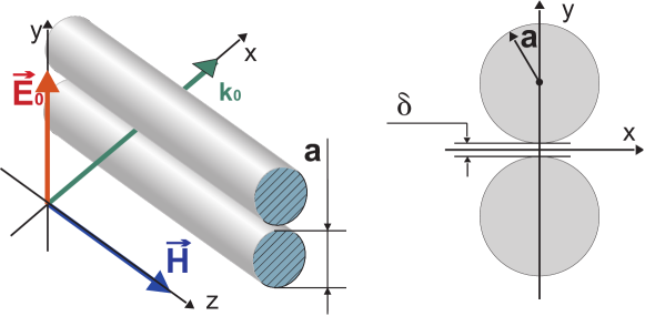
We examine scattering of an electromagnetic plane wave by two close metallic cylinders under the conditions of surface plasmonic resonance. The size of the cylinders in cross-plane is assumed to be of the order or less than the wavelength. FIG. 1 illustrates the system of two cylinders with circular cross sections together with the Cartesian coordinate system that we operate. The radii of both cylinders are equal to and the width of the gap between the cylinders is . We consider a particular case of TM-wave when the electric field of the incident wave is polarized along the line connecting the cylinders axes. Such choice is made because surface plasmon modes with red-shifted resonance frequencies and high local enhancement of the electric field in the gap between the cylinders Vorobev is achieved for this polarization only. The red shift corresponds to high negative value of the dielectric constants contrast (permittivity ratio) , where and are the permittivities of the metal and the surrounding dielectric respectively.
The complete system of Maxwell’s equations can be reduced to wave equation on the only nonzero magnetic field -component ,
| (1) |
where is the frequency of the incident wave. We assume the magnetic permeability to be unity both in metal and in surrounded space. The electric field is orthogonal to -axis, thus the problem becomes effectively two-dimensional. The electric field distribution can be restored as , where is two-dimensional antisymmetric tensor, , and runs values .
The numerical simulations were performed with commercially available software JCMsuite Sven . The software solves Maxwell’s equations based on a finite element method (FEM). It gives high advantages in simulations of structures with small curved elements. In particular, the package JCMsuite showed very good results in a benchmark simulation of plasmonic nano antennas Solvers-1 , which are similar to our structure. The simulations are challenging because of the narrow gap between cylinders. The studied system is under resonance condition and exhibits large field enhancement, so field distribution based adaptive meshing should be applied. An optimal number of refinement steps was found as well as a number of points on circuits in the vicinity of the gap for the manual mesh specification. A solution convergence based on posteriori error estimation was examined in the same way as in Sven and Solvers-2 .
For the modes under consideration, the magnetic field is symmetric with respect to the axis of the system and the electric field lines are normal to the axis. The fact allowed us to choose the computational domain which contains one half of the system shown in FIG. 1 and perfect metal boundary conditions at the axis.
Setting permittivity of surrounding medium in numerical simulations, we suppose that permittivity ratio is equal to complex metal permittivity and can be expressed as , i.e. is the real part of the permittivity and is the imaginary part.
In the following we use the term ‘model’ metal. By this we mean that we can arbitrarily assign any values to its permittivity at any wavelength in order to illustrate the dependence of certain quantities (eg. resonance conditions, field enhancement factor) on the parameters of the system. Having understood the general properties of plasmon modes in such systems we turn to investigation of the optical properties on silver cylinders. For silver, both the real and the imaginary parts of the dielectric permittivity are functions of the wavelength , which dependencies can be extracted from JohnsonKristy .
III Analytic solution
If the cylinders radius is much less than the wavelength in the outer space, , and the skin layer in the metal, , with being the free space wavenumber, it is possible to develop an analytical solution. One can neglect retardation effects and assume in Eq. (1), thus describing the system in the quasi-static approximation as a pair of cylinders in a homogenous external electric field. The solution of such problem depends on frequency implicitly via metal permittivity . This description is valid at distances close to the system, .
It is more convenient to use the electric field potential instead of the magnetic field in this approximation. The electric field is in the case. The reason is that the qualitative physical picture of the surface plasmon oscillations has clear explanation in terms of the potential . Maxwell’s equations are reduced to quasi-static equation
| (2) |
in the vicinity of the cylinders. Equation (2) reduces to Laplace equation inside and outside the cylinders: . The boundary conditions are the continuity of the potential and normal component of the electric displacement . The potential should tend to unperturbed external field potential far from the system, thus when , where is the electric field of the incident wave. Note here, that the symmetry of the external field potential in respect to -plane corresponds to the symmetry of potential in surface plasmons which are realized at high negative permittivity ratio .
Equation (2) does not explicitly contain dependence on the frequency. The dependence of the scattering properties of the system stems from the dependence of the metal permittivity on the frequency. Thus, the most dependencies presented in this paper are given in terms of the real part of the metal permittivity. Knowing dispersion of permittivity for a given metal one can rewrite all the dependencies in terms of frequency. Here we note that the plots are not changed dramatically in the case since the dependence of the metal permittivity is usually monotonic in the frequency domain under consideration.
In order to solve the above stated problem we use the so-called bipolar coordinates system: two dimensionless coordinates and are related to the Cartesian coordinates as follows:
| (3) |
The lines are the pairs of circles situated symmetrically in respect to -axis (see FIG. 1). By definition corresponds to the cylinder surfaces, that is . Reference system transformation (3) is a conformal map. The Laplace operator in bipolar coordinates is given by the following expression:
| (4) |
where is the scaling function.
The partial solutions of Laplace equation can be written as or in separated variables. In order to solve the problem of two cylinders in the external field one has to expand the potential in terms of these partial solutions. Using the symmetry we can write:
| (5) |
| (6) |
where is the potential inside the cylinders and is the induced part of the potential outside the cylinders. Coefficients and are to be found from the boundary conditions.
Now let us expand the potential of the external field in terms of partial solutions of Laplace equation. Simple but cumbersome calculations give:
| (7) |
The solution of the problem can be written explicitly ()
| (8) | |||||
For the coefficients , .
It follows from (8) that the resonance occurs when permittivity contrast takes values
| (9) |
Expression (6) allows one to calculate the amplitude of the electric field. Explicit expression for electric field components reads
| (10) |
| (11) |
In what follows, we use these expressions to evaluate the electric field spatial distribution in the vicinity of the cylinders.
IV Results for the limit of close cylinders
In this section we analyze the limit of two close cylinders, when the width of the gap between the cylinders is small compared to the cylinder radius , i.e. . The condition means that the dimensionless parameter in (3).
The resonance condition (9) becomes
| (12) |
with the limit . The result can be qualitatively explained as follows. The resonance condition enables the existence of standing surface plasmon waves in the flat region of the gap which has the approximate length Kaminov-Mammel_1974_ApplOpt . This is a general point, which is valid in the case of two close metal spheres as well Lebedev ; Klimov2007 . Expression (12) is valid until the retardation effects become important at the scale , thus the applicability condition is .
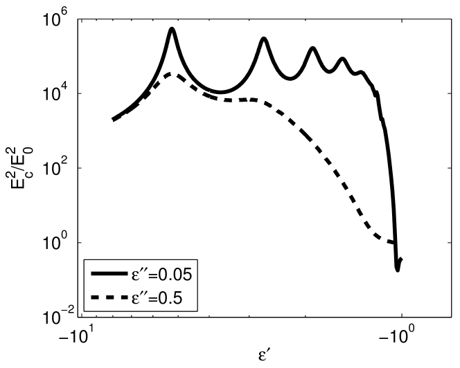
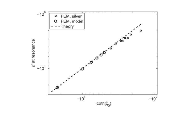
Numerical simulations results for positions of the resonances are shown on FIG. 2 for two different levels of Ohmic losses in metal. One can see maxima, which correspond to the resonances (9). The dependence of the position of the first resonance on the geometrical parameters of the system is plotted on FIG. 3, expression tends to at small gap width.
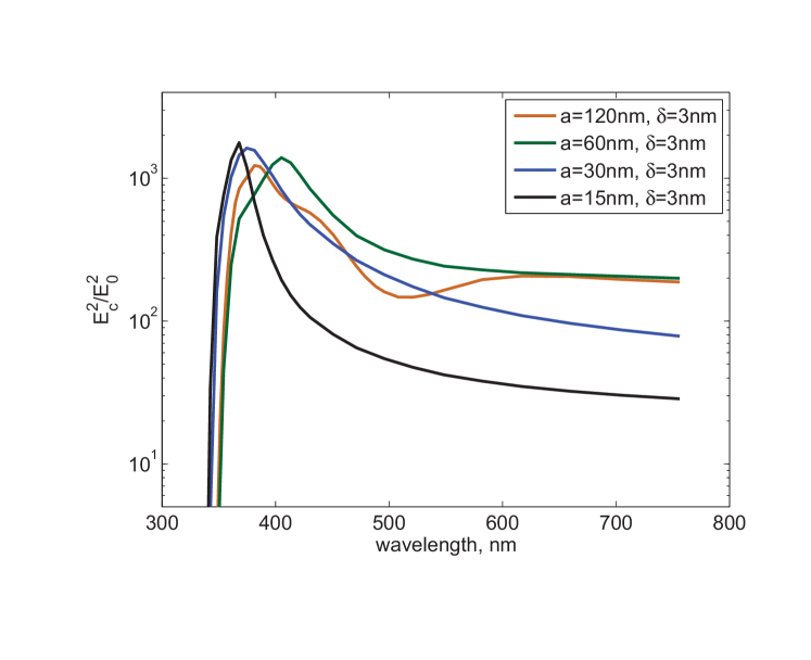
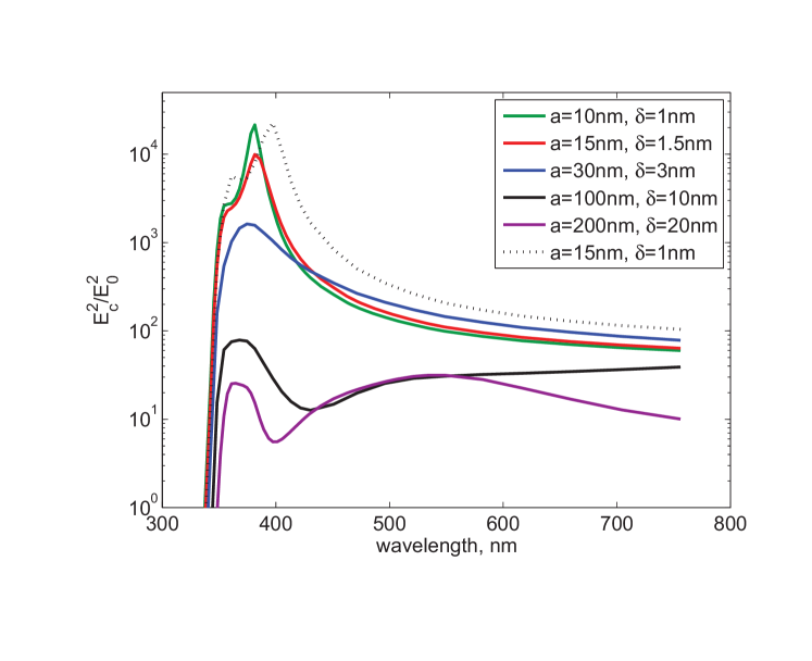
We performed numerical simulations for silver cylinders using experimental values of permittivity JohnsonKristy for silver. We chose the size of the system to be close and slightly below experimentally achieved (see, e.g. Bakker2008 ). Resonance permittivity (its real part) ratio as the function of geometrical parameters of the system is plotted on (see FIG. 3) Electric field enhancement in the center of the gap between the cylinders as a function of incident wavelength is plotted on FIG. 4, 5. On FIG. 4 all curves correspond to the same value of the gap width nm. On FIG. 5, all curves excepting that for nm, nm correspond to the same value of the ratio . When comparing the plots from these figures with FIG. 2, one should bear in mind that the absolute value of the real part of the dielectric permittivity of silver is monotonically increasing function of the wavelength . One can see, that at most only first two distinct resonance peaks can be observed for silver cylinders, due to the presence of Ohmic losses which lead to broadening and overlapping of all the rest peaks. Total losses increase with the size of the system, due to increase of radiation intensity. In FIG. 5, the local minimum near 430 nm and 400 nm of the enhancement factor in the case of cylinders with radii 100 nm and 200nm correspondingly should be ascribed to retardation effects. The same concerns the local minimum near 500 nm for the curve corresponding to nm in FIG. 4. For thinner cylinders, retardation does not lead to any qualitative effects. In fact, the form of the curve as a function of is independent of the absolute values of the cylinders radii and the gap thickness in the quasi-static limit. It is a function of the ratio only, that is of the parameter . This can be perceived from the general properties of Laplace equation, which solutions do not change after rescaling of the whole system. The curves are shifted to lower values of for large values of the cylinders’ radii due to radiation losses, the relative importance of which decreases with the wavelength (see (17) below).
Now let us examine in details the enhancement of the electric field in the gap when the real part of permittivity contrast is close to the first resonance position . One can see that in the vicinity of the resonance the contribution from the first harmonics in (6) is much larger than from all the rest. It follows from the symmetry of the problem that electric field on the -plane is directed normal to the plane and is equal to
| (13) |
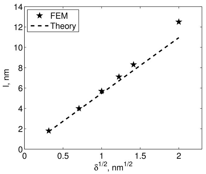
where we have taken into account the fact that . This expression is valid provided . Electric field changes its sign at , where
| (14) |
and this length should be interpreted as the mode size, i.e. wavelength of plasmon in flat dielectric gap with thickness between two bulk metal media Kaminov-Mammel_1974_ApplOpt .
Numerical simulation results for the mode size as a function of geometrical parameters of the system are shown in FIG. 6. The expression (14) is consistent with our qualitative explanation (12) and is valid under the same condition .
It follows from (13) that the field at the center of the gap is
| (15) |
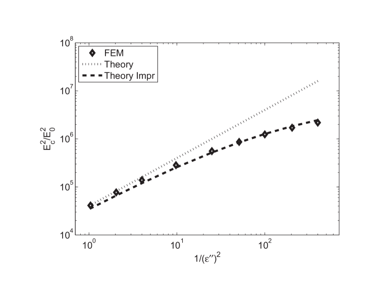
The first representation in (15) is written for general case, whereas the second one is valid for the limit of closely located cylinders. At the resonance, i.e. real part , Eq. (15) is reduced to . The field enhancement at the resonance as a function of imaginary part of the permittivity contrast is shown in FIG. 7. The deviation of the enhancement factor in numerical simulations from the analytical prediction (15) at small is due to radiation losses which become important for these values of , whereas law (15) accounts for Ohmic losses in metal only. The radiation losses are determined mainly by the dipole radiation since the size of the system is much less than the wavelength. The dipole moment of the system (per unit length) , can be extracted from far asymptotics of the electric field (13). Radiation losses per unit length can be estimated as . The Ohmic losses in metal can be estimated by multiplying the dissipation ratio per unit volume by the volume, occupied by the field . Thus the dissipation rate (per unit length of cylinders) is estimated as . Expression (15) is valid provided , that is while .
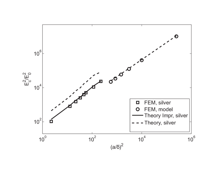
The field enhancement at the resonance in the gap between the cylinders as a function of geometrical parameters is plotted on FIG. 8. For model metal we assume wavelength of µm, which means that the radiation losses are small compared to the Ohmic ones. For silver cylinders the deviation of the enhancement factor from law (15) is substantial. This is due to the fact that wavelength at the resonance frequency is not well above the size of the system.
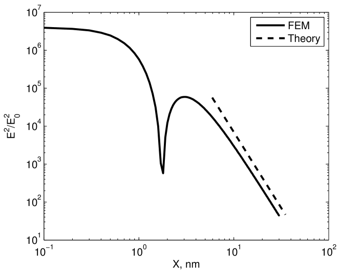
At scales expression (13) gives quadratic decay law of the electric field as a function of coordinate
| (16) |
The qualitative explanation of this law for scales is as follows. The potential difference between the surfaces of the cylinders is constant at the scales since surface plasmon wavelength in the gap of thickness is much larger than the typical . Thus , where is the gap width at given . The potential difference can be related to the electric field strength at the center of the gap through the condition that the full surface charge on each cylinder is zero. The surface charge has different signs inside the flat region at distances and outside the region (the size of the mode). The electric field can be assumed to be uniform in -direction across the gap, thus . The value of this integral is mostly formed at lower limit and finally one finds . To check the decay law (16) in numerical experiment, we chose extremely small value of the gap to provide large difference between scales and , the result is presented on FIG. 9.
Decaying law (16) for larger scales, , corresponds to field of dipole , the asymptotics is valid for any value of the ratio . Note, that the dipole moment is formed at scales , and the minor part of the total surface charge is involved in the process. In fact, the dipole moment can be estimated as the integral over the region , . The integral is formed at distances , where only the small part of surface charge is located. Inner region does not give feasible contribution in due to the small charge separation length.
One can improve Eq. (15) by taking into account the radiation losses. As a result, the resonance value of dielectric permittivity (9) achieves imaginary negative contribution , . The correction can be extracted from the condition, that dipole radiation is equal to power supplied to the system from external electric field provided Ohmic losses are zero, . The intensity of the radiation is , and the power supplied to the system is , where is assumed to be real and is the imaginary part of the dipole moment induced in the system. At resonance conditions, dipole moment is pure imaginary, thus we find . Comparing the result with (15), we obtain
| (17) |
where should be determined from (9). The correction is valid if and is applicable for arbitrary ratio of cylinders’ radii and the inter-cylinder distance, including the case when . In FIG. 7 and 9 theoretical curves which take into account the radiation correction (17) are presented. The curves fit numerical data quite good, thus the deviation of the data curve from the theoretical prediction (15) with pure real should be assigned just to unaccounted radiation losses.
V Conclusion
We have numerically investigated the distribution of electro-magnetic field induced by the incident plane wave near a system of two closed parallel metallic cylinders of nanoscale dimensions modeled by Maxwell’s equations. The comparison of the results of the numerical simulation with the analytical solution for the plasmon modes in the system governed by Maxwell’s equations in the quasistatic limit showed agreement between these two approaches.
The position of the resonance is determined by the geometrical characteristics of the gap between the cylinders. Resonance corresponds to existence of standing wave inside the almost flat part of the gap, which can be thought of as a plane metal-dielectric-metal structure. Since the wavelength of the plasmon depends on its frequency (through permittivity of metal), there exist a set of resonance frequencies corresponding to the set of standing modes in the gap. Comparison with numerical simulations gives a good agreement, since the dimension of the gap is smaller than the size of the whole metallic granules, and the quasi-static approximation used in the analytical theory has high accuracy.
The analytically obtained Vorobev field enhancement factor in the center of the gap for the first resonance has also good agreement with that obtained numerically. It is determined both by Ohmic losses in the metal and radiative losses, the relative importance of the radiative losses rises with the dimension of the system. We assumed the radii of the cylinders to be of the order of 100 nm, which is implemented in experiments Bakker2008 . The skin layer depth in metal is of the same order thus the quasi-static approximation has some deviations from the exact solution of the Maxwell’s equations.
Finally, we studied the dependence of the field enhancement for the case of silver cylinders with permittivity taken from experimental data. Our numerical simulations for such systems showed that only the Ohmic losses are reasonable, and only the first two resonances can be really observed.
The authors thank V.V. Lebedev and I.R. Gabitov for fruitful discussions and Lin Zschiedrich for assistance with numerical simulations. The work is partially supported by Russian Federal Targeted Programs ”S&S-PPIR”, ”I&DPFS&T” and German Academic Exchange Service (DAAD).
References
- (1) M. Suzuki, A. Takada, T. Yamada, T. Hayasaka, K. Sasaki, E. Takahashi, S. Kumagai, “Low-reflective wire-grid polarizers with absorptive interference overlayers,” Nanotechnology 21, 175604 (2010)
- (2) Y. Ekinci, H.H. Solak, Ch. David, and H. Sigg, “Bilayer Al wire-grids as broadband and high-performance polarizers,” Optics Express 14, 2323 (2006)
- (3) R.M. Bakker, H-K. Yuan, Z. Liu, V.P. Drachev, A.V. Kildishev, V.M. Shalaev, R.H. Pedersen, S. Gresillon, A. Boltasseva, “Enhanced localized fluorescence in plasmonic nanoantennae,” Applied Physics Letters 92, 043101 (2008)
- (4) J. Zhang, Y. Fu, M.H. Chowdhury, and J. R. Lakowicz, “Metal-enhanced single-molecule fluorescence on silver particle monomer and dimer: coupling effect between metal particles,” Nano Letters 7, 2101 (2007)
- (5) D. Bloemendal, P. Ghenuche, R. Quidant, I. G. Cormack, P. Loza-Alvarez, and G. Badenes, “Local Field Spectroscopy of Metal Dimers by TPL Microscopy,” Plasmonics 1, 41 (2006)
- (6) P.K. Jain, W. Huang, and M.A. El-Sayed, “On the Universal Scaling Behavior of the Distance Decay of Plasmon Coupling in Metal Nanoparticle Pairs: A Plasmon Ruler Equation,” Nano Letters 7, 2080 (2007)
- (7) J. Berthelot, A. Bouhelier, C. Huang, J. Margueritat, G. Colas-des-Francs, E. Finot, J-C. Weeber, A. Dereux, S. Kostcheev, H.I.E. Ahrach, A-L. Baudrion, J. Plain, R. Bachelot, P. Royer, G.P. Wiederrecht “Tuning of an optical dimer nanoantenna by electrically controlling its load impedance,” Nano Letters 9, 3914 (2009)
- (8) Zh.-K. Zhou, M. Li, Zh.-J. Yang, X.-N. Peng, X.-R. Su, Z.-S. Zhang, J.-B. Li, N.- Ch. Kim, X.-F. Yu, L. Zhou, Zh.-H. Hao, and Q.-Q. Wang “Plasmon-Mediated Radiative Energy Transfer across a Silver Nanowire Array via Resonant Transmission and Subwavelength Imaging,” ACS Nano 4, 5003 (2010)
- (9) S.A. Maier, P.G. Kik, H.A. Atwater, S. Meltzer, E. Harel, B.E. Koel, A.A.G. Requicha “Local detection of electromagnetic energy transport below the diffraction limit in metal nanoparticle plasmon waveguides,” Nature Materials 2, 229 (2003)
- (10) A.W. Sanders, D.A. Routenberg, B.J. Wiley, Y. Xia, E.R. Dufresne, and M.A. Reed, “Observation of plasmon propagation, redirection, and fan-out in silver nanowires,” Nano Letters 6, 1822 (2006)
- (11) J. Clarkson, J. Winans, and P. Facuhet, “On the scaling behavior of dipole and quadrupole modes in coupled plasmonic nanoparticle pairs,” Optical Materials Express 1, 970 (2011)
- (12) I. Romero, J. Aizpurua, G.W. Bryant, and F.J. Garcia De Abajo, “Plasmons in nearly touching metallic nanoparticles: singular response in the limit of touching dimers,” Optics Express 14, 9988 (2006)
- (13) V. Amendola, O.M. Bakr, and F. Stellacci, “A Study of the Surface Plasmon Resonance of Silver Nanoparticles by the Discrete Dipole Approximation Method: Effect of Shape, Size, Structure, and Assembly,” Plasmonics 5, 85 (2010)
- (14) Y. Cheng, M. Wang, G. Borghs, and H. Chen, “Gold nanoparticle dimers for plasmon sensing,” Langmuir: the ACS journal of surfaces and colloids 27, 7884 (2011)
- (15) G. Haran, “Single-molecule Raman spectroscopy: a probe of surface dynamics and plasmonic fields,” Accounts of Chemical Research 43, 1135 (2010)
- (16) P.M. Morse and H. Feshbach, Methods of theoretical physics. Part II (McGraw-Hill, New York, 1953)
- (17) A.D. Boardman, and B.V. Paranjape, “The optical surface modes of metal spheres,” Journal of Physics F: Metal 7, 1935 (1977)
- (18) D.Yu. Fedyanin, A.V. Arsenin, V.G. Leiman and A.D. Gladun, “Backward waves in planar insulator metal insulator waveguide structures,” Journal of Optics 12, 015002 (2010)
- (19) I.P. Kaminow, W.L. Mammel, and H.P. Weber, “Metal-Clad Optical Waveguides: Analytical and Experimental Study,” Applied Optics 13, 396 (1974)
- (20) C.A. Pfeiffer, E.N. Economou, and K.L. Ngai, “Surface polaritons in a circularly cylindrical interface: surface plasmons,” Physical Review B 10, 3038 (1974)
- (21) P. Nordlander, C. Oubre, E. Prodan, K. Li, and M. I. Stockman, “Plasmon Hybridization in Nanoparticle Dimers,” Nano Letters 4, 899 (2004)
- (22) S.V. Zhukovsky, C. Kremers, and D.N. Chigrin, “Plasmonic rod dimers as elementary planar chiral meta-atoms,” Optics Letters 36, 2278 (2011)
- (23) M. Hentschel, D. Dregely, R. Vogelgesang, H. Giessen, and N. Liu, “Plasmonic oligomers: the role of individual particles in collective behavior,” ACS Nano 5, 2042 (2011)
- (24) J. Petschulat, C. Menzel, A. Chipouline, C. Rockstuhl, A. Tuennermann, F. Lederer, T. Pertsch, “Multipole approach to metamaterials,” Physical Review A 78, 043811 (2008)
- (25) D.N. Chigrin, C. Kremers, and S.V. Zhukovsky, “Plasmonic nanoparticle monomers and dimers: From nano-antennas to chiral metamaterials,” Applied Physics B 105, 81 (2011)
- (26) V. Lebedev, S. Vergeles, and P. Vorobev, “Giant enhancement of electric field between two close metallic grains due to plasmonic resonance,” Optics Letters 35, 640 (2010)
- (27) V.V. Klimov, and D.V Guzatov, “Strongly localized plasmon oscillations in a cluster of two metallic nanospheres and their influence on spontaneous emission of an atom,” Physical Review B 75, 24303 (2007)
- (28) P.E. Vorobev, “Electric field enhancement between two parallel cylinders due to plasmonic resonance,” Journal of Experimental and Theoretical Physics 110, 193 (2010)
- (29) A.M. Michaels, J. Jiang, and L. Brus, “Ag nanocrystal junctions as the site for surface-enhanced Raman scattering of single rhodamine 6G molecules,” J.Phys.Chem. B 104, 11965 (2000)
- (30) J. Pomplun, S. Burger, L. Zschiedrich, F. Schmidt, “Adaptive finite element method for simulation of optical nano structures,” Physica Status Solidi (b) 244, 3419 (2007)
- (31) J. Hoffmann, C. Hafner, P. Leidenberger, J. Hesselbarth, S. Burger, “Comparison of electromagnetic field solvers for the 3D analysis of plasmonic nanoantennas,” Proc. SPIE 7390, 73900J (2009)
- (32) S. Burger, R. Köhle, L. Zschiedrich, W. Gao, F. Schmidt, R. März, Ch. Nölscher, “Benchmark of FEM, waveguide and FDTD algorithms for rigorous mask simulation,” Proc. SPIE 5992, 599216 (2005)
- (33) M.H. Davis, “Two Charged Spherical Conductors in a Uniform Electric Field: Forces and Field Strength,” The Quarterly Journal of Mechanics and Applied Mathematics 17, 499 (1964)
- (34) A.E.H. Love, “Some Electrostatic Distributions in two Dimensions,” Proceedings of the London Mathematical Society s2-22, 337 (1924)
- (35) P.B. Johnson, and R.W. Christy, “Optical Constants of the Noble Metals,” Physical Review B 6, 4370 (1972)