Evolutionary optimization of optical antennas
Abstract
The design of nano-antennas is so far mainly inspired by radio-frequency technology. However, material properties and experimental settings need to be reconsidered at optical frequencies, which entails the need for alternative optimal antenna designs. Here a checkerboard-type, initially random array of gold cubes is subjected to evolutionary optimization. To illustrate the power of the approach we demonstrate that by optimizing the near-field intensity enhancement the evolutionary algorithm finds a new antenna geometry, essentially a split-ring/two-wire antenna hybrid which surpasses by far the performance of a conventional gap antenna by shifting the n=1 split-ring resonance into the optical regime.
pacs:
84.40.Ba, 73.20.Mf, 02.60.-x, 78.67.BfLight-matter interaction, i.e. absorption and emission of light as well as the control of its spectral and directional properties, can be optimized by means of antenna-like plasmonic nano structures Bharadwaj et al. (2009); Biagioni et al. (2012). This is of immediate importance in diverse fields of research ranging from solar energy conversion Atwater and Polman (2010), photocatalytic Liu et al. (2011) and sensing applications Becker et al. (2010) to single-particle manipulation Juan et al. (2009); Zhang et al. (2010) and spectroscopy Kinkhabwala et al. (2009) as well as quantum optics and communication Akimov et al. (2007); Kolesov et al. (2009); Huang et al. (2009); Jacob and Shalaev (2011).
RF-antenna designs are usually optimized for thin, infinitely good conducting wires that only support surface currents and are typically fed by transmission lines connected by infinitely narrow gaps Balanis (1992). For antennas at optical frequencies the general operation conditions deviate substantially from such ideal behaviour: (i) Antenna wire diameters are comparable to the electromagnetic penetration depth into the wire material leading to volume currents Dorfmueller et al. (2010). In the case of noble metals, such wires therefore exhibit plasmon resonances in the visible spectral range resulting in a reduced effective wavelength of wire waves Novotny (2007). (ii) Feeding (excitation) of optical antennas is often achieved by focused laser beams or quantum emitters. (iii) high-frequency-related effects such as the ’kinetic inductance’ become significant Zhou et al. (2005). It can therefore not be taken for granted that RF-inspired antenna designs, like dipole Mühlschlegel et al. (2005), bow tie Schuck et al. (2005); Farahani et al. (2005) and Yagi-Uda antennas Taminiau et al. (2008); Curto et al. (2010), represent ’optimal’ geometries also at optical frequencies, although they provide a reasonable performance.
Evolutionary algorithms (EAs) find optimized solutions to highly complex non-analytic problems by creating subsequent generations of individuals coded by their respective genomes that compete for the right to pass on their properties, according to a fitness parameter Sivanandram and Deepa (2008). These optimized solutions can then be analyzed to foster the understanding of underlying physical principles. Evolutionary optimization has successfully been applied in various fields of research, including pulse shape optimization in coherent control of chemical reactions Baumert et al. (1997) and field localization in plasmonic structures Aeschlimann et al. (2007, 2010). Furthermore, evolutionary optimization has been used to aid the development of radio-wave antennas Huang et al. (2007); Pantoja et al. (2007). First attempts to employ such methods to find improved plasmonic nanostructures have also been undertaken Ginzburg et al. (2011); Kessentini et al. (2011); Forestiere et al. (2010, 2012), however, the investigated configurational space remained very limited.
Here we employ the method of evolutionary optimization in a more general setup to find improved plasmonic antenna structures that, in terms of near-field intensity enhancement (fitness parameter), outperform the best radio-wave-type reference antennas by a factor of two. Analysis of the fittest antenna reveals that it is a split-ring/two-wire antenna hybrid (Split-Ring-Antenna), which merges features of the fundamental magnetic resonance of a split ring with the fundamental electric resonance of a linear dipole antenna both in the visible wavelength regime.
Methods
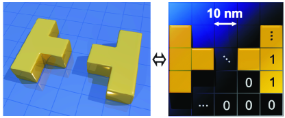
As fitness parameter we choose the normalized near-field intensity enhancement in the focus of an illuminating Gaussian beam (647 nm, NA, 4.3 fs pulse duration, 144 nm bandwidth). A genetic representation of complex-shaped thin-film nano antennas is realized by composing structures (matrix antennas) from discrete gold cubes with fixed dimensions (10x10x11 nm3) positioned on a 2121 square matrix in vacuum oriented perpendicular to and centered on the optical axis of the Gaussian beam. The fields of such structures can be described by local Maxwell equations.
The resulting configuration space of about 4 different individual structures ensures geometrical variety but is impossible to explore by brute force methods, since the evaluation of an individual structure takes about 20 minutes. The size of the focal spot and the area occupied by the gold cube matrix are comparable (see Fig. S1 sup ). An example showing a bow-tie antenna represented in a 55 array is depicted in Fig. 1. The genetic information is represented in a unique binary code, where Matrix elements are set to ’1’, if occupied by a gold cube and to ’0’ when empty (for a calculation of the number of physical redundant structures see Fig. S2, S3 and related discussion).
We solve Maxwell’s equations using the finite-difference time-domain (FDTD) method Taflove and Hagness (2005) (FDTD Solution, Lumerical Inc., Canada). Due to the discretization in space (Yee Cells, dx = 1 nm), adjacent gold cubes are fully connected to each other. We also obtain conductive bridges between neighbouring gold blocks that contact each other via their edges. All simulation objects were shifted by half a Yee cell size in - and -direction to ensure identical dimensions of gold cubes and voids. In order to describe the dielectric function of gold in a sufficiently wide spectral range we use the data by Johnson and Christy fitted by an analytical model Etchegoin et al. (2006).
The evolutionary algorithm is implemented in MatLab 111All necessary code written in Lumerical script language or MatLab can be made available upon request.. It uses generations consisting of 20 or 30 individual matrix antennas. The five best structures according to the fitness parameter are selected as parents for the next generation. With carefully chosen mechanisms for crossover and mutation of the genomes, consecutive generations constantly improve in the sense that their fitness parameter increases. To create descendants in a first step one of the five parents is selected by roulette wheel selection Sivanandram and Deepa (2008) with a probability that is proportional to its fitness (parent ). Three methods, i.e. creation of random structures, mutation as well as linear and spiral genome crossing, are then applied until a total of 20 (or 30) new individuals have been generated for the next generation (see Fig. S4).
After a sufficient amount of generations has been simulated, a so called toggle plot analysis is performed, which consists of running 21x21 simulations in which every block is toggled individually. Colour-coding the block positions according to the magnitude of the fitness changes associated with the individual toggle event shows the relative importance of single blocks, the potential for further improvement of a matrix antenna, and also eventually produces new individuals with enhanced fitness 222This is the brute force realization of the hill climber algorithm on our setup, neglecting pair- and higher-order correlations..
Results
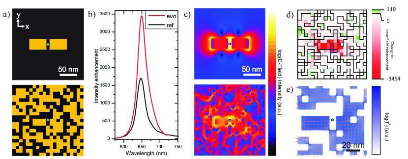
The wavelength coincides with the resonance of a linear dipole nano antenna consisting of two end-to-end aligned 463011 nm3 gold rods (width = 3 cubes, height = 1 cube) separated by a 10 nm gap (Fig. 2(a), top panel) which serves as a reference structure. It exhibits a resonant normalized near-field intensity enhancement of about 1800 in the center of its feed gap. Other geometries, such as bow-tie antennas, were also tested but do not yield higher fitness.
In the following we discuss the fittest structure obtained by running the EA for 100 generations with 20 individuals each (see Fig. S5 for development of geometry and fitness parameter), a subsequent toggle plot analysis and further 30 generations with 30 individuals each, starting with combinations of the best five structures obtained from the toggle plot analysis.
The best matrix antenna structure (Fig. 2 (a), lower panel) exhibits a remarkably high fitness, as indicated by its near-field spectrum in Fig. 2(b) which is recorded in the optimization point (indicated as blue dot in (a)) after a broadband excitation. Its maximal near-field intensity enhancement of 3500 is nearly twice as high as that of the reference antenna. Both spectra show single nearly Lorentzian peaks (Q=20 and 23, respectively; see supplementary information for a further discussion of the Q-factor).
According to the reciprocity theorem Bharadwaj et al. (2009); Biagioni et al. (2012) the optimized antenna should also improve the radiative properties of a quantum emitter positioned in the spot of highest field enhancement. Indeed for the reference antenna we find a radiation enhancement of 2126 and a radiation efficiency of 0.255, while for the fittest antenna the radiation enhancement is 4271 with a radiation efficiency of 0.268. Surprisingly, the directivity of the fittest antenna remains very similar to that of the reference antenna despite its complex shape (see Fig. S6 and related discussion).
The fittest matrix antenna exhibits three noticeable geometrical features:
(i) a small gap in the center between two compact rod(-like) structures, being slightly displaced in y-direction with respect to the observation point.
(ii) a single gold block directly below the gap which creates a current path connecting the rod-like structures and
(iii) a seemingly random arrangement of gold blocks further away from the center.
It is important to note that the optimal structure found by a genetic algorithm depends on both the available primitive elements as well as on possible boundary conditions. Using a different block size or imposing boundary conditions, e.g. limiting the gap width, would lead to different fittest structures.
We now consider the near-field intensity enhancement maps of both reference and matrix antenna in Fig. 2(c). The small displacement of the rod-like structures increases the near-field intensity enhancement by a small factor because of the proximity of the corners of the rod-like structures to the point of optimization. However, this alone by far cannot explain the observed increase of the near-field intensity enhancement. The achievable enhancement by displacing the reference antenna in a similar way amounts to a factor of 1.1.
The result of a toggle plot analysis is displayed in Fig. 2(d). It indicates that changing individual blocks does not yield considerable additional near-field intensity enhancement, but rather a severe reduction. We therefore believe that the structure’s fitness is close to a (local) maximum in the configuration space. The by far strongest reduction of fitness occurs when toggling gold blocks near the center. This indicates that the compact structure in the proximity of the gap is dominating the field enhancement and is most critical for achieving the observed performance. Assuming that it is excited at an Eigenmode, this also explains the appearance of a single narrow Lorentzian resonance. As apparent from the toggle plot, the random structures far away from the center do hardly influence the field enhancement in the gap. Nevertheless, it is possible that collective effects of the peripheral blocks do influence the fitness of the structure to some extend which due to the inherent complexity will not be further discussed in detail.
Of particular interest is the single gold block below the gap. It provides a current path via the cube edges between the two rod-like structures that form the gap as can be seen by taking a closer look at the currents in the central part of the matrix antenna in Fig. 2(e). Surprisingly, we find that removing this block severely lowers the fitness of the resulting matrix antenna instead of increasing it. Closer inspection of Fig. 2(e) reveals two particular current paths, one located in the rod-like structures corresponding to a bonding linear dipolar nano antenna mode, but also a second one, which flows from one upper gap edge through the connecting gold block to the other upper gap edge, corresponding to a fundamental split ring mode.
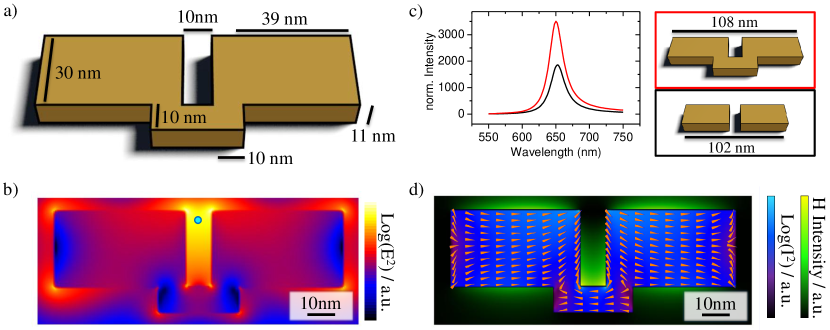
In order to better understand the effects that lead to the increased near-field intensity enhancement, in the following we study a reduced model system, i.e. a mixture of a split-ring and a linear two-wire antenna called split-ring antenna (SRA) that retains the important features of the fittest matrix antenna but can be described by a small number of freely tunable parameters. Its geometry is depicted in Fig. 3(a). The structure can be interpreted either as linear two-wire antenna with an asymmetric short circuit, a split-ring resonator with attached wires or a long single nano wire that is deformed in a particular way.
The near-field intensity enhancement of the SRA in the center plane is depicted in Fig. 3(b), showing a strong field concentration towards the open side of the SRA gap as it was already observed in the best matrix antenna. Fig. 3(c) compares the spectra of the resonances of a SRA with a non short-circuited dipolar antenna of identical arm cross section, gap size and resonance frequency. Both spectra were obtained at the point of highest near field enhancement along the -axis. Also in the present model system the split-ring antenna surpasses the classical dipole antenna design in terms of maximum near-field intensity enhancement by a factor of 2.
Also in the model system the current pattern can be decomposed into a fundamental (n=1) split-ring mode Rockstuhl et al. (2006) and a dipolar current in each antenna arm which is running 180∘ out-of-phase to the current in the short circuit (Fig. 3 (d)), adding to the charge accumulation in the upper part of the gap and thus increasing the near-field intensity enhancement. Since the resonance is in the optical regime, the SRA is a way to circumvent the limitation of pure split-ring resonances to wavelengths above 900 nm due to the kinetic inductance Zhou et al. (2005). The SRA represents a magnetic dipole in the visible, showing magnetic fields (Fig. 3 (d)), which are only by a factor of 2.5 weaker than those of the isolated split-ring resonator at its resonance wavelength of 908 nm.
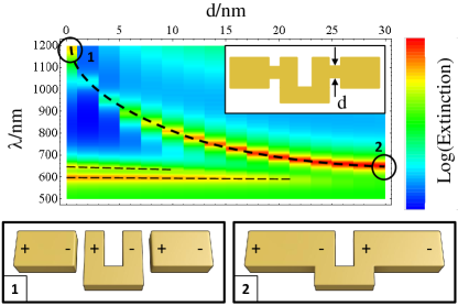
To confirm the shift of the fundamental split-ring mode from the infrared into the visible spectral range, we place two gold bars (35x30x11 nm3) separated by a 5 nm non conductive gap from the plain split-rings ends. The extinction cross section is examined while connecting the gold bars with the split-ring via successively thicker gold bridges at the center of the gap (see Fig. 4 and inset). In the unconnected geometry the fundamental split-ring resonance is shifted into the red to about 1200 nm due to the capacitive coupling across the gap. As the connection grows thicker (increasing ), the fundamental split-ring mode is shifted by more than 500 nm from the infrared into the visible. The shift of the resonance is of similar origin as the emergence of a charge transfer mode for a dipolar antenna with a conductive bridge Schnell et al. (2009). However, here the fundamental split-ring mode is not disappearing but its phase is inverted (compare the charge distributions sketched in the lower panel of Fig. 4). For very thin conductive bridges both modes exist simultaneously (see also Schnell et al. (2009)) and cancel out each other, leading to a dip in the extinction cross section.
Conclusion
We show that by using the method of evolutionary optimization in a large parameter space, high-fitness plasmonic antennas can be found within a reasonable amount of time. The method can be adapted to a large variety of fitness parameters in order to optimize plasmonic structures for various purposes. Besides directly yielding optimized structures, careful analysis of the working principles of the resulting geometries may provide new design strategies for high-performance plasmonic nano structures.
In the present example we obtain an increase of the near-field intensity by nearly a factor of two caused by the intriguing cooperation of a fundamental split-ring mode and dipole antenna resonance. We have used the latter principle to devise a novel antenna design which additionally exhibits very large magnetic fields at optical frequencies. In particular, the fundamental split-ring resonance is shifted into the visible spectral range because of the formation of a charge-transfer-like hybrid resonance with two rods of a dipolar antenna. The method can be further adapted to include geometrical constraints imposed by micro fabrication and therefore can lead to structures that can directly be implemented in practical applications.
Acknowledgements
Markus Kiunke wants to thank Christoph Brüning, Thorsten Feichtner and Oleg Selig want to thank Jord C. Prangsma and Paolo Biagioni for fruitful discussions. Financial support by the DFG is gratefully acknowledged (HE5618/1-1).
References
- Bharadwaj et al. (2009) P. Bharadwaj, B. Deutsch, and L. Novotny, Adv. Opt. Phot. 1, 438–483 (2009).
- Biagioni et al. (2012) P. Biagioni, J.-S. Huang, and B. Hecht, Rep. Prog. Phys. 75, 024402 (2012).
- Atwater and Polman (2010) H. A. Atwater and A. Polman, Nat. Mater. 9, 205 (2010).
- Liu et al. (2011) Z. Liu, W. Hou, P. Pavaskar, M. Aykol, and S. B. Cronin, Nano Letters 11, 1111 (2011), http://pubs.acs.org/doi/pdf/10.1021/nl104005n .
- Becker et al. (2010) J. Becker, A. Trügler, A. Jakab, U. Hohenester, and C. Sönnichsen, Plasmonics 5, 161 (2010).
- Juan et al. (2009) M. L. Juan, R. Gordon, Y. Pang, F. Eftekhari, and R. Quidant, Nat. Phys. 5, 915 (2009).
- Zhang et al. (2010) W. Zhang, L. Huang, C. Santschi, and O. J. F. Martin, Nano Letters 10, 1006 (2010).
- Kinkhabwala et al. (2009) A. Kinkhabwala, Z. Yu, S. Fan, Y. Avlasevich, K. Muellen, and W. E. Moerner, Nat. Photon. 3, 654 (2009).
- Akimov et al. (2007) a. V. Akimov, a. Mukherjee, C. L. Yu, D. E. Chang, a. S. Zibrov, P. R. Hemmer, H. Park, and M. D. Lukin, Nature 450, 402 (2007).
- Kolesov et al. (2009) R. Kolesov, B. Grotz, G. Balasubramanian, R. J. Stohr, A. A. L. Nicolet, P. R. Hemmer, F. Jelezko, and J. Wrachtrup, Nat. Phys. 5, 470 (2009).
- Huang et al. (2009) J.-S. Huang, T. Feichtner, P. Biagioni, and B. Hecht, Nano Letters 9, 1897 (2009).
- Jacob and Shalaev (2011) Z. Jacob and V. M. Shalaev, Science 334, 463 (2011).
- Balanis (1992) C. A. Balanis, Proc. IEEE 80, 7 (1992).
- Dorfmueller et al. (2010) J. Dorfmueller, R. Vogelgesang, W. Khunsin, C. Rockstuhl, C. Etrich, and K. Kern, Nano Letters 10, 3596 (2010).
- Novotny (2007) L. Novotny, Phys. Rev. Lett. 98, 266802 (2007).
- Zhou et al. (2005) J. Zhou, T. Koschny, M. Kafesaki, E. N. Economou, J. B. Pendry, and C. M. Soukoulis, Phys. Rev. Lett. 95, 223902 (2005).
- Mühlschlegel et al. (2005) P. Mühlschlegel, H.-J. Eisler, O. J. F. Martin, B. Hecht, and D. W. Pohl, Science 308, 1607 (2005).
- Schuck et al. (2005) P. Schuck, D. Fromm, A. Sundaramurthy, G. Kino, and W. Moerner, Phys. Rev. Lett. 94, 017402 (2005).
- Farahani et al. (2005) J. N. Farahani, D. W. Pohl, H.-J. Eisler, and B. Hecht, Phys. Rev. Lett. 95, 017402 (2005).
- Taminiau et al. (2008) T. H. Taminiau, F. D. Stefani, and N. F. Van Hulst, Opt. Expr. 16, 10858 (2008).
- Curto et al. (2010) A. G. Curto, G. Volpe, T. H. Taminiau, M. P. Kreuzer, R. Quidant, and N. F. van Hulst, Science 329, 930 (2010).
- Sivanandram and Deepa (2008) S. Sivanandram and S. Deepa, Introduction into genetic algorithms (Springer Verlag Berlin Heidelberg, 2008).
- Baumert et al. (1997) T. Baumert, T. Brixner, V. Seyfried, M. Strehle, and G. Gerber, Appl. Phys. B: Lasers and Optics 65, 779 (1997).
- Aeschlimann et al. (2007) M. Aeschlimann, M. Bauer, D. Bayer, T. Brixner, F. J. García de Abajo, W. Pfeiffer, M. Rohmer, C. Spindler, and F. Steeb, Nature 446, 301 (2007).
- Aeschlimann et al. (2010) M. Aeschlimann, M. Bauer, D. Bayer, T. Brixner, S. Cunovic, F. Dimler, A. Fischer, W. Pfeiffer, M. Rohmer, C. Schneider, F. Steeb, C. Strüber, and D. V. Voronine, Proc. Natl. Acad. of Sci. USA 107, 5329 (2010).
- Huang et al. (2007) H. Huang, A. Hoorfar, and S. Lakhani, Antennas and Propagation Society International Symposium, 2007 IEEE 1, 1609 (2007).
- Pantoja et al. (2007) M. F. Pantoja, A. R. Bretones, S. Member, R. G. Martin, and S. Member, IEEE Trans. Antennas Propag. 55, 1111 (2007).
- Ginzburg et al. (2011) P. Ginzburg, N. Berkovitch, A. Nevet, I. Shor, and M. Orenstein, Nano Letters 11, 2329 (2011).
- Kessentini et al. (2011) S. Kessentini, D. Barchiesi, T. Grosges, and M. de la Chapelle, Evolutionary Computation (CEC), 2011 IEEE Congress on 1, 2315 (2011).
- Forestiere et al. (2010) C. Forestiere, M. Donelli, G. F. Walsh, E. Zeni, G. Miano, and L. D. Negro, Opt. Lett. 35, 133 (2010).
- Forestiere et al. (2012) C. Forestiere, A. J. Pasquale, A. Capretti, G. Miano, A. Tamburrino, S. Y. Lee, B. M. Reinhard, and L. Dal Negro, Nano Letters 12, 2037 (2012).
- (32) See Supplemental Material at [URL will be inserted by publisher].
- Taflove and Hagness (2005) A. Taflove and S. C. Hagness, Computational electrodynamics: the finite-difference time-domain method, 3rd ed., edited by A. Taflove (Artech House, Inc., 2005).
- Etchegoin et al. (2006) P. G. Etchegoin, E. C. L. Ru, and M. Meyer, J. Chem. Phys 125, 164705 (2006).
- Note (1) All necessary code written in Lumerical script language or MatLab can be made available upon request.
- Note (2) This is the brute force realization of the hill climber algorithm on our setup, neglecting pair- and higher-order correlations.
- Rockstuhl et al. (2006) C. Rockstuhl, F. Lederer, C. Etrich, T. Zentgraf, J. Kuhl, and H. Giessen, Opt. Expr. 14, 8827 (2006).
- Schnell et al. (2009) M. Schnell, A. Garcia-Etxarri, A. J. Huber, K. Crozier, J. Aizpurua, and R. Hillenbrand, Nat. Photon. 3, 287 (2009).