Vacuum Faraday effect for electrons
Abstract
The optical Faraday effect describes the rotation of linear polarization upon propagation through a medium in the presence of a longitudinal magnetic field. The effect arises from a different phase delay between the right and left handed polarisation components of the light. In this paper we predict a Faraday effect for a completely different system: electron vortices. Free electron vortex states were recently observed in transmission electron microscopy experiments, and they introduce new degrees of freedom into the probing of matter with electron beams. We associate a rotation of a vortex superposition with the fact that different phases are acquired by oppositely handed vortices propagating in a magnetic field. We show that, in contrast to the optical Faraday effect, the rotation of the electron beam occurs in vacuum and arises from the intrinsic chirality of the constituent vortex states.
pacs:
(42.50.Tx) Optical angular momentum and its quantum aspects, (41.75.Fr) Electron and positron beams, (42.25.Lc) Birefringence, (03.65.Vf) Phases: geometric; dynamic or topological1 The optical Faraday effect and its generalisation for electron waves
Michael Faraday reported in 1845 that the polarisation of light can be affected by magnetic fields, an effect that now bears his name. Since then, the Faraday effect has found numerous metrological and research applications, including the ultra-sensitive detection of magnetic fields, [1, 2], or of fields generated by electron plasmas in interstellar space and the ionosphere [3, 4].
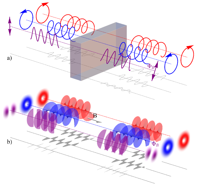
Faraday noted that the polarisation direction of light is rotated after passing through “heavy glass” exposed to a longitudinal magnetic field. We now understand that the Faraday effect arises from the different speed of propagation of right and left handed circularly polarised light through an optically active medium. The associated difference in accumulated phase between the circular components of linearly polarised light results in a rotation of the polarisation direction.
One of the intriguing properties of light is that it can carry angular momentum: a spin contribution associated with circular polarisation (), but also orbital angular momentum (OAM) [5, 6]. While circular polarisation describes a rotation of the electric field vector upon propagation, the orbital angular momentum (OAM) is a feature of ’twisted’ light beams. The OAM can take on arbitrary multiples of depending on how tightly wound the phase fronts are. These so-called “vortex beams” have a rotational intensity pattern and are associated with a phase dependence , where is a non-zero integer and the azimuthal angle.
Strictly speaking, Faraday rotation is not a relevant concept for optical OAM. The reason is that there is no intrinsic mechanism in a gyromagnetic medium to produce the required OAM state dependent dispersion, because selection rules forbid coupling of the OAM to the atomic electron degrees of freedom. This is consistent with results from a recent experiment in which no rotation was observed for a superposition of right and left handed OAM states (a Hermite-Gauss mode) propagating through cholesteric liquid crystals [7]. We note that a relative phase shift between right and left handed OAM components will appear as a rotation of the intensity pattern [8]. Such phase shifts can be induced by spinning the medium through which the light propagates, inducing a ‘mechanical’ Faraday rotation, as demonstrated recently in a slow light medium [9].
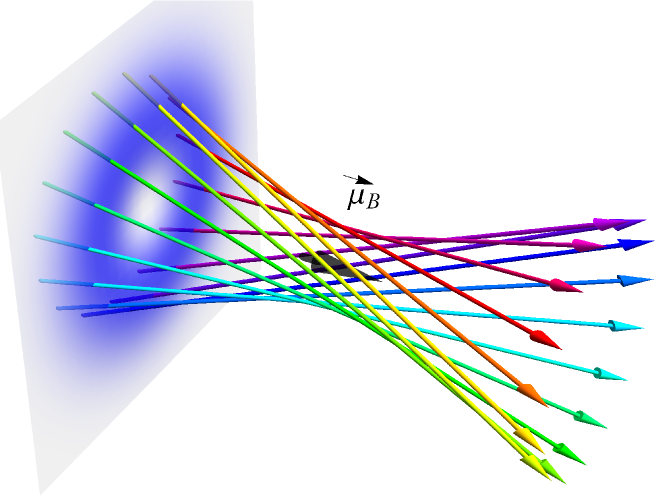
Electron vortices are unusual quantum states that have only recently been predicted [10] and produced in transmission electron microscopy (TEM) experiments [11, 12]. Electron vortex beams have the same geometrical properties as their optical counterparts, being characterised by an angular dependence related to units of OAM, but they also produce features that have no analogue in optics. In particular the circulation of charge in an electron vortex beam gives rise to an arbitrarily large orbital magnetic moment (Fig. 2), distinct from the magnetic moment due to spin [10, 13]. Hence electron vortices can couple to electronic degrees of freedom through dipole selection rules forbidden to optical vortices [14].
Given the analogies (and differences) between optical and electron vortices, the question arises: Do electron vortex waves undergo something analogous to an optical Faraday effect? Here we show that there is indeed a Faraday rotation arising through Zeeman interaction from propagation parallel to a uniform, external magnetic field (i.e. in a geometry where there is no Lorentz force).
2 Electron vortex states
The dynamics of a non-relativistic electron propagating in a uniform longitudinal magnetic field (with associated vector potential ) is described by the Hamiltonian
| (1) |
where and are the electron mass and charge, respectively. The Hamiltonian contains the kinetic energy due to the canonical momentum and the Zeeman interaction of the electron spin with an arbitrary external magnetic field . The electron’s two-component spinor wavefunction satisfies the Pauli equation . Here is the operator for the magnetic moment, is the Bohr magneton, is the Landé g-factor for electron spin and is the vector of Pauli spin matrices . In agreement with typical parameters in transmission electron microscopes ( nA/nm2), we assume that beam currents are sufficiently low so that Coulomb repulsion can be neglected.
In the case of the uniform magnetic field directed along the axis, a suitable choice for the vector potential is . Exploiting the cylindrical symmetry of the system, the Hamiltonian can be put in the form
| (2) |
Here denotes the Larmor frequency, and are the operators for the component of OAM and spin, respectively, where is the spin quantum number. The first term gives the kinetic energy of motion along , which is the same as in field-free space; the second and third terms together give the energy for the transverse motion, and have the form of the Hamiltonian for a harmonic oscillator with characteristic frequency ; the final term gives the Zeeman energy, with contributions from both OAM and spin.
With Hamiltonian (2) the spinor components decouple and we can find monochromatic wave solutions which obey the time independent Schrödinger equation for a scalar wavefunction . This problem can be solved exactly for eigenstates with given components of OAM and momentum [15]. Separating the degrees of freedom,
| (3) |
we identify the radial modes
| (4) |
where is a characteristic width which depends on the magnitude of the magnetic field, and is an associated Laguerre polynominal. The radial modes are characterised by the OAM quantum number, , and the radial mode number which denotes the number of radial nodes of the electron density function. The radial profile of a mode with and is shown in Fig. 2. The transverse beam profile, given by , is the same as that of the Laguerre-Gauss beams familar from optical vortices, as was also pointed out in [16].
Recognising that the combined second and third term in (2) describe a 2D harmonic oscillator, which in polar coordinates has energy eigenvalues , the eigenvalues for the total energy are the well known Landau levels
| (5) |
The corresponding allowed wave numbers are then
| (6) |
where is the total energy determined by the electron source, and is the wave number for a plane (non-vortex) wave propagating freely along the axis. For electron vortices, the phase aquired upon propagation depends on the magnetic field. We see from (6) that there is a path that depends upon the direction of the angular momentum through the signs of and . This corresponds to a phase acquired upon propagation which depends (via the Larmor frequency) on the magnetic field and is proportional to the total angular momentum comprising both a spin and an orbital component.
If the magnetic energy is small compared to the total energy (a situation justified e.g. for electrons in TEM experiments), i.e. , we can apply the paraxial approximation to the wave numbers (6). The corresponding phase shift accumulated along the trajectory of the vortex then comprises three parts:
| (7) |
where is a spatial frequency which corresponds to the Larmor temporal frequency . The first term describes the phase evolution in free space; the second depends on the energy of the transverse motion due to the magnetic field, and the third term arises from the Zeeman interaction with the total angular momentum. In the following it is this latter term which is important, as it causes a different phase shift for vortex states with opposite helicity. We note that electrons in superpositions of left and right spin components should result in a spin Faraday rotation, analgous to optics. Here we concentrate on OAM Faraday rotation for which there is no optical counterpart.
Just like for the optical Faraday effect, the differential phase shifts become observable as a rotation angle for electrons in superpositions of vortex states with opposite handedness. As they originate from the interaction of the magnetic dipole moment with the external field, the electron Faraday effect does not require the mediation of an optically active medium but occurs in vacuum!
3 Considerations on observing the Faraday effect for electrons
Electron vortex states have recently been generated in transmission electron microscopes (TEM) via diffraction from nano-fabricated holograms [12, 17, 18, 19]. Using suitably designed holograms, also superpositions of vortex states can be generated (see B). The required shape of the holograms is determined by the interference pattern of the target state with a reference wave function, e.g. a plane or spherical wave, resulting in transverse or longitudinal separation of the diffraction orders respectively.
In order to realise electron Faraday rotation we require electrons in a superposition of two modes with the same spin and radial mode number but opposite vorticity . The probability density then has an azimuthal dependence
| (8) |
where we define
| (9) |
For this is a petal pattern consisting of maxima equally spaced around a circle, which after propagating through a region of a longitudinal magnetic field is rotated through the angle . The maxima are separated by phase singularity lines, where the phase changes by and the probability density vanishes. For the case of the transverse profile, shown in Fig. 3, is that of the Hermite-Gaussian mode. Here the analogy with optical polarization is clearest, with the components corresponding to the right and left handed circular polarization states, and the nodal line to the linear polarization.
While the phase change depends on , the rotation of the intensity pattern is independent of . The Laguerre-Gauss modes form a complete basis with which an arbitrary wavefunction can be described, and therefore any intensity and phase profile will rotate through the same angle [8].
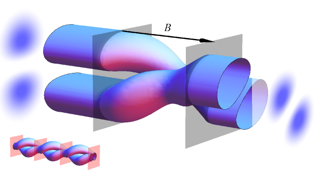
So far we have considered the eigenstates of (2) with a transverse scale determined by the magnetic field strength through the parameter . A beam with the same radial profile but a width is, however, no longer an eigenstate and will therefore change upon propagation. Solving the paraxial wave equation, (see A) we find that the radial profile retains the same Laguerre-Gauss form, only now expands and contracts periodically in time, or equivalently with propagation distance (16). This contraction happens at twice the Larmor frequency and hence twice every full rotation. The width variation can be understood in terms of the competition between diffraction, which dominates when , and the confining effect of the magnetic field, which dominates when . This is illustrated in Figure 3.
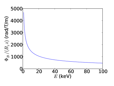
The rotation angle , depends on the initial kinetic energy of the electrons, as detailed in (9); as slow electrons spend more time in the magnetic field, their rotation angle is larger. While optical Faraday rotation is characterised by the Verdet constant (a proportionality constant of rotation angle per propagation distance and magnetic field strength), the electron ‘Verdet’ parameter varies with kinetic energy (see Fig. 4).
Even with low-energy transmission electron microscopy, measuring the proposed deflection due to an interaction with a perpendicularly-magnetised sample remains challenging, in particular the neccessity to distinguish Faraday rotation from the usual cycloid motion of an electron beam within magnetic lenses. Ignoring relativistic corrections, typical values (keV, sample thickness = nm, longitudinal field T) yields a rotation about the beam axis of 0.06mrad. In certain geometries differential phase contrast techniques routinely measure deflections of this magnitude, when the rotation can be projected by long camera lengths to give measurable deflections. A more promising experimental approach will be to consider low energy electron beams. Low energy photoelectrons ejected by circularly polarised photons are also known to carry orbital angular momentum [20] and the subsequent propagation of these electrons through magnetic thin films may also visualise Faraday effects.
4 Conclusions
We have demonstrated that for electron vortex states propagating in a longitudinal magnetic field the Zeeman interaction produces an OAM dependent dispersion. This results in a rotation of the probability density of a superposition of vortex states about the beam axis, analogous to the optical Faraday effect. To the best of our knowledge this is a new concept, it is an effect that is not present in optics, and it may lead to applications in electron spectroscopy. The magnitude of the rotation scales with the magnitude of the magnetic field, and increases with decreasing energy. There are a number of interesting applications which may follow. OAM Faraday rotation provides the possibility of spatially resolved measurements of longitudinal magnetic field components, analogous to the measurement of transverse fields in Lorentz microscopy, by measuring the rotation angle of a vortex superposition. Moreover, we note that in the approximation considered here, spin and OAM are separately conserved. This would not be expected for relativistic non-paraxial beams [13] or spatially varying magnetic fields [21], suggesting a route to investigating intrinsic spin-orbit coupling in an electron vortex beam, via a spin-dependence of the rotation angle.
Appendix A Calculation of beam width variation using the paraxial approximation
To find the propagation of a beam with a given beam waist we evaluate the time-independent Schrödinger equation with Hamiltonian (2) as before in the paraxial approximation. We assume a solution of the form
| (10) |
where is an envolope function which describes the evolution of the beam profile upon propagation. is as defined in the main text. If varies sufficiently slowly with we can use the paraxial approximation
| (11) |
Then, substituting (10) into the Schrödinger equation, we arrive at the paraxial wave equation
| (12) |
The first two terms here are the same as in the paraxial equation for an optical beam propagating in vacuum, or for an electron beam in field-free space. The third term represents the confining effect of the magnetic field, and the final term gives the Zeeman interaction. For an OAM eigenstate with , the last term takes a constant value . We can then factor out the phase due to the Zeeman interaction by writing
| (13) |
for some function . then satisfies the equation
| (14) |
This equation has the same form as the equation from paraxial optics for a medium with quadratically varying refractive index , where and are constants (see for example [22]), only here . Such an optical system supports Laguerre-Gauss type modes which experience a periodic width variation due to the competition between diffraction and the focusing effect produced by the refractive index variation. A similar effect is described in [23], for the propagation of vortex wavepackets in a transverse field.
The solutions can be written [24, 25] as
| (15) | |||||
where is the beam width, is the wavefront radius of curvature and gives the longitudinal phase shift. The equation (15) is the same as for the LG modes in free space, except here the functions , and are different. Choosing to coinside with one of the minima of , and calling this minimum value , the width function can be written, for the electron beam in a magnetic field, as
| (16) |
Appendix B Diffraction grating patterns for production of electron vortex superpositions
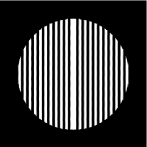
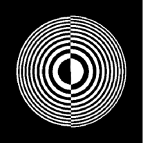
For interference with a plane wave , in which case the diffraction orders will be separated transversely, a suitable hologram pattern is generated from
| (17) |
where specifies the orientation of the singularity lines. A grating producing a superposition of and modes in the first diffraction order is shown in Fig. 5, where we have chosen . Note that the left and right sides of the grating are displaced by half a period with respect to one another, introducing the necessary phase shift. In a similar way a hologram which separates the diffracted beam components longitudinally rather than transversely could be used [18, 19]. An example of this type of grating is shown in Fig. 5. This is calculated using the same method, only with the plane wave factor replaced with the spherical wave profile , where is a constant which determines the curvature of the wavefront, and hence the spacing of the diffraction orders. Such grating patterns can be produced in the same way as those already used to generate single vortex modes. We note that gratings that generate superpositions of vortex beams with beams that have flat phasefronts have recently been generated and used to investigate the Gouy phase for electrons [26].
References
- [1] S. I. Kanorsky, A. Weis, J. Wurster, and T. W. Hänsch. Quantitative investigation of the resonant nonlinear faraday effect under conditions of optical hyperfine pumping. Phys. Rev. A, 47:1220–1226, 1993.
- [2] G. Labeyrie, C. Miniatura, and R. Kaiser. Large Faraday rotation of resonant light in a cold atomic cloud. Phys. Rev. A, 64:033402, 2001.
- [3] J. W. Warwick and G. A. Dulk. Faraday rotation on decametric radio emissions from jupiter. Science, 145(3630):380–383, 1964.
- [4] M. Mendillo. Storms in the ionosphere: patterns and processes for total electron content. Reviews of Geophysics, 44(RG4001), 2006.
- [5] D. L Andrews. Structured light and its applications. Academic Press, 2008.
- [6] S. Franke-Arnold, L. Allen, and M. J. Padgett. Advances in optical angular momentum. Laser Photonics Rev., 2(4):299–313, 2008.
- [7] W. Löffler, M. P. van Exter, G. W. ’t Hooft, G. Nienhuis, D. J. Broer, and J. P. Woerdman. Search for Hermite-Gauss mode rotation in cholesteric liquid crystals. Opt. Express, 19(14):12978–83, 2011.
- [8] L. Allen and M. J. Padgett. Equivalent geometric transformations for spin and orbital angular momentum of light. J. Mod. Opt., 54(4):487–491, 2007.
- [9] S. Franke-Arnold, G. Gibson, R. W. Boyd, and M. J. Padgett. Rotary Photon Drag Enhanced by a Slow-Light Medium. Science, 333(6038):65, 2011.
- [10] K. Y. Bliokh, Y. P. Bliokh, S. Savel’ev, and F. Nori. Semiclassical dynamics of electron wave packet states with phase vortices. Phys. Rev. Lett., 99(19):190404, 2007.
- [11] M. Uchida and A. Tonomura. Generation of electron beams carrying orbital angular momentum. Nature (London), 464(7289):737–9, 2010.
- [12] J. Verbeeck, H. Tian, and P. Schattschneider. Production and application of electron vortex beams. Nature (London), 467(7313):301–4, 2010.
- [13] K. Y. Bliokh, M. R. Dennis, and F. Nori. Relativistic electron vortex beams: angular momentum and spin-orbit interaction. Phys. Rev. Lett., 107:174802, 2011.
- [14] S. Lloyd, M. Babiker, and J. Yuan. Quantized orbital angular momentum transfer and magnetic dichroism in the interaction of electron vortices with matter. Phys. Rev. Lett., 108:074802, Feb 2012.
- [15] L.D. Landau and E.M. Lifshitz. Quantum Mechanics: Non-Relativistic Theory. Pergamon Press, 1977.
- [16] K. Y. Bliokh, P. Schattschneider, J. Verbeeck, and F. Nori. Electron vortex beams in a magnetic field: A new twist on Landau levels and Aharonov-Bohm states. arXiv. 1204.2780v2, 2012.
- [17] B. J. McMorran, A. Agrawal, I. M. Anderson, A. A. Herzing, H. J. Lezec, J. J. McClelland, and J. Unguris. Electron vortex beams with high quanta of orbital angular momentum. Science, 331(6014):192–5, 2011.
- [18] J. Verbeeck, H. Tian, and A. Béché. A new way of producing electron vortex probes for STEM. Ultramicroscopy, 113:83–87, 2012.
- [19] K. Saitoh, Y. Hasegawa, N. Tanaka, and M. Uchida. Production of electron vortex beams carrying large orbital angular momentum using spiral zone plates. J. Electron Microsc., 0(0):1–7, 2012.
- [20] D. A. MacLaren. Asymmetric photoelectron transmission through chirally-sculpted, polycrystalline gold. Phys. Chem. Chem. Phys., 11, 2009.
- [21] G. A. Gallup, H. Batelaan, and T. J. Gay. Quantum-mechanical analysis of a longitudinal stern-gerlach effect. Phys. Rev. Lett., 86(20):4508–4511, 2001.
- [22] A. E. Siegman. Lasers. University Science Books, 1986.
- [23] G. M. Gallatin and B. McMorran. Propagation of vortex electron wave functions in a magnetic field. Phys. Rev. A, 86:012701, Jul 2012.
- [24] P. K. Tien and J. P. Gordon. Focusing of a light beam of Gaussian field distribution in continuous and periodic lens-like media. Proceedings of the IEEE, 1965.
- [25] M. Newstein and B. Rudman. LaGuerre-Gaussian periodically focusing beams in a quadratic index medium. IEEE Journal of Quantum Electronics, 23(5):481–482, May 1987.
- [26] Agrawal A. Anderson I. M. Herzing A. Lezec H. J. McClelland J. J. Unguris J. McMorran, B. J. Electron Beams Carrying Quantized Orbital Angular Momentum. Laser Science, OSA Technical Digest (Optical Society of America, 2011), paper LWL1., 2011.