Muon Collider: Plans, Progress and Challenges
Abstract
We in the physics community expect the LHC to uncover new physics in the next few years. The character and energy scale of the new physics remain unclear, but it is likely that data from the LHC will need to be complemented by information from a lepton collider which can provide for precise examination of new phenomena. We describe the concept, accelerator design, and detector R&D for a high energy Muon Collider as well as the challenges associated with the machine and its detector environment.
I Muon Colliders - Who Ordered That?
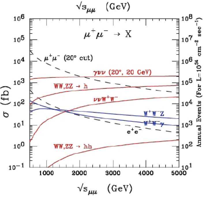
The use of muons in a high energy collider appears to be a desperate measure. After all muons have a lifetime of and will only survive for about 2000 turns in a 1.5 TeV storage ring. But muons also have distinct advantages as projectiles in a colliding beams accelerator. They are pointlike, so one can adjust the center of mass energy of the collision precisely and study resonance structures and threshold effects in great detail. Secondly, they are 207 times more massive than the electron, meaning that muons radiate times less than an electron traveling with he same radius of curvature and energy. This means that a muon collider is a circular, rather than a linear, machine. It also means that beamsthralung effects, radiation due to beam-beam interactions, would be much smaller in a muon collider than an machine, allowing for precise beam constraints and energy measurements. Finally the mass-dependent coupling of the Higgs to the () system is 40,000 times larger than the coupling to , making a muon collider an ideal candidate for direct study of s channel Higgs.
Muons in a storage ring are reused, each muon has 2000 chances to collide with the opposing beam before it decays. This relaxes requirements on emittance and makes constraints on beam dimensions much more forgiving than a linear collider with its extremely tight beam focussing requirements. Such a machine would also be compact, with machines up to 5 TeV fitting on the Fermilab site. The machine is also likely to use significantly less power than a comparable electron collider. Initial calculations indicate the wall power needed for a 3 TeV Muon Collider would be 1/3 of that for a 3 TeV CLIC and 2/3 of that for a 0.5 TeV ILC (Table 1). A muon collider could scale to multi-TeV energies without excessive penalties in power or cost.
I.1 Accelerator Challenges
The short muon lifetime means that everything must be done quickly. Muons must be produced and collected, cooled, and re-accelerated rapidly. This forces many of the components to provide multiple functions, combining cooling, acceleration, and focussing. The beam transport system must handle the radiation and heat load associated with electrons from muon decay. Detectors must be well-shielded from the bulk of the decay backgrounds. The Muon Accelerator Program (MAP) MAP has been organize to study the many technical challenges associated with a Muon Collider.
Figure 1 shows a schematic of a possible Muon Collider Complex. The front-end muon source would use protons from a 4 MW accelerator (e.g. Project X) impinging on a mercury jet target. This is followed by a decay channel, beam bunching and bunch rotation, and an initial cooling stage. This first stage could be identical to the front end of a Neutrino Factory. The initial section is followed by a cooling section that would further cool the beam in both momentum and position space. Finally the muons are accelerated in a multi-racetrack section before being injected into the storage ring. The Muon Collider accelerator is described in more detail in Mike Zisman’s contribution to this conferenceZisman and in publications of the Muon Accelerator Program Mucol Palmer:2007zzc .

I.1.1 Ionization Cooling
Previously used beam cooling techniques, such as stochastic or electron cooling will not cool a muon beam quickly enough for the muons to be used in a collider. Instead, muons will be cooled utilizing ionization energy loss, combining a low Z absorber ’with a high field solenoid and normally conducting RF cavity. Muons lose both transverse and longtitudinal momentum in the absorber. The RF restores longtudinal momentum, reducing . Multiple scattering acts to reheat the muons, resulting in an equilibrium emittance that is proportional to . The optimum absorber material has maximum energy loss per radiation length. Liquid hydrogen is the best candidate. Muon cooling ideas are being tested in the MICE experiment at RAL. This experiment will measure the properties of single muons before and after passing through an ionization cooling sectionKaradzhov:2010zz .
I.1.2 RF Breakdown
After the absorber longitudinal momentum of the muon is restored by accelerating the beam through an rf cavity. The overall cooling effect is more efficient when a solenoid focuses the beam while still in the cavity. Unfortunately, the breakdown voltage of an RF cavity is significantly degraded in a magnetic field Stratakis:2009zz . Electrons are emitted from the cavity surface in regions which are not perfectly smooth. These electrons are guided in the magnetic field and impact on localized regions on the wall of the cavity. In the absence of a field the electrons tend to be more dispersed and the resulting impact damage damage is not localized. The MAP program is studying how these effects can be mitigated by improving the surface material properties (beryllium coatings) or by interrupting the free flow of the field-emitted electrons by filing the cavity with gas Freemire:2011zz .
I.1.3 Neutrino Radiation
Muons in the collider ring decay at the rate of . At this rate the radiation due to interacting neutrinos at the site boundary is a concern. The neutrino interaction rate increases as . Local hot spots will occur which correspond to straight sections in the storage ring. Off site radiation can be minimized by limiting the length of straight sections, increasing the depth of the collider ring, and managing the operating parameters to maximize luminosity/dose. However, neutrino-induced radiation may be the practical limit to the maximum energy of a machine located on the Fermilab site.
| CLIC | ||||
|---|---|---|---|---|
| CM Energy | 1.5 | 3.0 | 3.0 | TeV |
| Luminosity | 1 | 2-4 | 2 | |
| rms bunch height | 6 | 4 | 0.001 | |
| Diameter/length | 2 | 4 | 48 | km |
| Wall power | 147 | 159 | 560 | MW |
II Physics and Detector Studies
Although there is a revived muon accelerator effort, there has been little corresponding detector effort which could study the large beam-related backgrounds with modern simulation tools and detector technologies. This effort was commissioned at the Muon Collider 2011 meeting in Telluride at the end of June 2011. Initial studies were performed using ILCROOT, LCSIM, and GEANT frameworks, with the goal of understanding the characteristics of the backgrounds and what sorts of tools would be needed to build a detector for the Muon Collider environment.
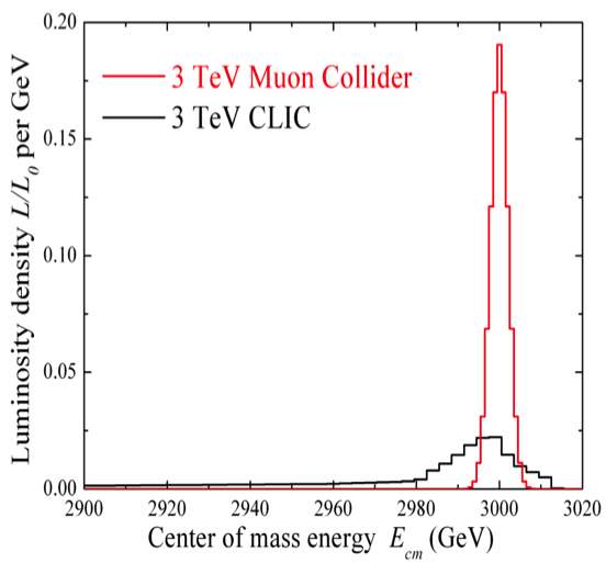
Both CLIC and the Muon Collider would need to study new phenomena with a level of precision that can not be achieved at LHC. The experimental conditions in CLIC and the Muon Collider are quite different. CLIC has a bunch train with 0.5 ns bunch spacing. The Muon Collider will have a single bunch each of and , colliding at intervals. Energy spread of the colliding beams scales as . The effect of this on the center of mass energy resolution is shown in figure 2. The excellent Muon Collider energy resolution allows for precise measurements of s-channel resonances and precise turn-on threshold scans. The higher muon mass means that there is a significant rate for s-channel Higgs-like particle production which is not available in a machine. Finally, although the muon beams are born polarized, the large phase space acceptance at low pion momentum needed for efficient muon collection means that the colliding beam polarization is likely to be below 20%. Additional polarization can be obtained at the expense of luminosity by limiting the initial phase space acceptance.


II.1 Machine-Detector Interface and Backgrounds
The physics environment of the Muon Collider is dominated by very large flux of high energy electrons from muon decay. These electrons interact in the beam transport system as well as in the shielding around the interaction point. Carefully designed shielding, both for the experiment and the beam transport system is necessary to keep backgrounds manageable. A feature that distinguishes the Muon Collider from other experiments is a tungsten/borated polyethylene “nose” that extends at a angle 6 cm from the interaction point. The cone is designed to absorb the intense electromagnetic radiation due to muon decay that accompanies the muon beams and reduces the overall background level by three orders of magnitude. Over the past year there has been a substantial effort to fully model the backgrounds in a model detector at the Muon Collider. There are now both MARS and G4beamline models of the interaction region with detailed simulations of the particle flux.
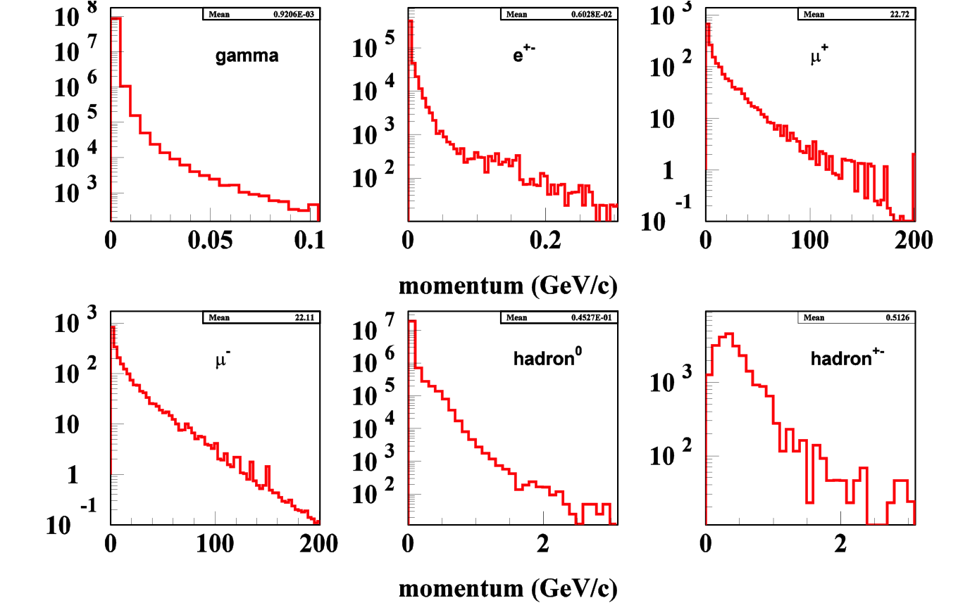
Figure 3 shows the background flux entering the detector region in a typical Muon Collider interaction. Total non-ionizing background is about 10% that of the LHC, but the crossing interval is 400 times longer, resulting in high instantaneous flux. The background is very different in character than that of either the LHC or CLIC. It is dominated by soft photons and low energy neutrons emerging from the shielding surrounding the detector. A typical background event has 164 TeV of photons, 172 TeV of neutrons, and 184 TeV of muons. With the exception of muons and charged hadrons the background spectrum is dominated by low energy particles. Only a small fraction of the background originates from the vicinity of the interaction region. This means that most of the decay background is out of time with respect to particles originating from the collision.

II.2 Background Rejection Techniques
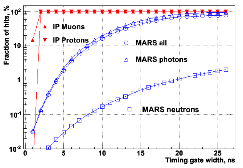
The fact that much of the background is soft and out of time gives us two handles on the design of an experiment that can cope with the high levels of background. Timing is especially powerful. Figure 3 shows the fraction of background and signal hits in the tracker preserved as a function of the width of the timing gate. An important feature is that the local gate t=0 is defined as the time when relativistic particle emerging from the interaction point arrives at the detector. Therefore a very tight cut can be made, still preserving the bulk of the tracks of interest. A 1 ns cut rejects two orders of magnitude of the overall background and about 4 orders of magnitude of neutron background.
A detailed tracking study was performed using the ILCROOT framework which includes a all silicon detector similar to the one proposed for SiDMazzacane . The tracker is fully pixelated with pixels in the tracker and pixels in the vertex section. Hits are required to have a threshold of 3000 electrons, which eliminates much of the soft photon and neutron background. Reconstructed tracks are required to have an impact parameter less then 3 mm. With no timing cut the reconstruction program fails due to the large number of hits. However if the cut is 3 ns only 11 background tracks are found and a 1 ns cut further reduces this to 3 tracks, all with low momentum. Replacing the timing cut by a time stamp would allow the hit arrival time to be used in the track fit, providing both background rejection and some level of particle identification.
Soft, uncorrelated hits can also be eliminated by exploiting the correlation between two closely spaced tracking layers. This was first suggested by Steve Geer in early Muon Collider studies and a similar concept is being explored for a track trigger for CMSLipton:2011zz . In that design two silicon sensors are spaced by a 1 mm thick interposer and only hits which are correlated between the top and bottom layers are used for the trigger. Initial studies indicate that such an arrangement would also be extremely effective at reducing Muon Collider backgrounds and might reduce dependence on the timing cut.

Timing is also crucial for calorimetry. Our initial ILCROOT simulation studied a dual readout “Adriano” heavy glass/scintillator calorimeter with cm cells with 7.5 interaction lengths Vito . There are two longitudinal sections 20 and 160 long, each with front and rear readout through SIPMs. Different timing cuts are used for the scintillation and Cerenkov light in the front section (15 and 6 ns, respectively) with a 22 ns cut for the rear section. In the central barrel region backgrounds deposit an average energy per tower of 5.33 GeV per event with RMS fluctuations of 540 MeV in the front section. The rear section sees an average energy of 630 MeV with fluctuations of 430 MeV. Further analysis will be needed to optimize cuts and determine jet energy resolution.
An optimal calorimeter design might combine fast timing with the reconstruction ability of pixelated calorimeters being studied for particle flow. A pixelated imaging sampling calorimeter with 200 square cells was proposed by R. Raja Raja . In this design a 2 ns “traveling trigger” gate referenced to the time of flight with respect to the beam crossing is used to reject out-of-time hits. In this case background rejection was found to be to . This sort of calorimeter can implement compensation by recognizing hadronic interaction vertices and using the number of such vertices to correct the energy. Initial estimates of the resolution of such a compensated calorimeter is . In contrast to relativistic tracks and electromagnetic showers, hadronic showers can take significant time to developsimon . Further study is needed to understand the tradeoff between background rejection provided by a short time gate and the loss of energy resolution caused by the slow time development of hadronic showers .
We have learned that tracking seems possible in a Muon Collider detector. Calorimetery is more challenging, but progress is being made on imaging calorimeter concepts that appear to meet the physics needs. Precise timing and pixelated detectors will be crucial to a successful Muon Collider detector. Both come at a cost. For example the time resolution, . The signal/noise and gain-bandwidth of typical electronic front ends are proportional to the transductance of the front end transistor - which in turn is proportional to front-end current. This means that electronics will necessarily dissipate significant power and, in contrast to planned ILC detectors, detectors for the Muon Collider will have to be water cooled with associated increase in mass. The large background of non-ionizing radiation means that silicon detector will have to be kept cold, around -10 C, again increasing the detector mass. Such a detector will resemble an LHC experiment more closely than those planned for ILC or CLIC.
III Conclusions
Both accelerator and detector aspects of a muon collider are extremely challenging. The Muon Accelerator Program has been formed to study and evaluate the accelerator challenges. A complementary effort in now beginning to study physics and detector aspects. Initial results of these studies indicate that detectors can be designed that withstand the fierce backgrounds. Such a detector is likely to be more massive than a corresponding ILC detector, but could have unique capabilities. Fast timing and fine segmentation appear to be crucial.
References
- (1) http://map.fnal.gov/
- (2) ICFA Beam Dynamics Newsletter No. 55, August 2011. http://www-bd.fnal.gov/icfabd/Newsletter55.pdf
- (3) Mike Zisman, submitted to Proc. of the DPF-2011 Conference, Providence, RI, August 8-13, 2011 arXiv:1109.3086v1 [physics.acc-ph]
- (4) R. B. Palmer, J. S. Berg, R. C. Fernow, J. C. Gallardo, H. G. Kirk, Y. Alexahin, D. Neuffer, S. A. Kahn et al., [arXiv:0711.4275 [physics.acc-ph]].
- (5) Y. Karadzhov, “Status of MICE, the international Muon Ionisation Cooling Experiment,” PoS ICHEP2010, 323 (2010).
- (6) D. Stratakis, J. C. Gallardo, R. B. Palmer, AIP Conf. Proc. 1222 (2010) 303-307.
- (7) B. Freemire et al., “High Pressure RF Cavity Test at Fermilab,” PAC-2011-MOP032.
- (8) Corrado Gatto, TIPP 2011
- (9) Nikolai Mokhov, Muon Collider 2011, https://indico.fnal.gov/getFile.py/access?contribId=5&sessionId=2&resId=0&materialId=slides&confId=4146
- (10) Sergei Striganov, Muon Collider 2011, https://indico.fnal.gov/getFile.py/access?contribId=17&sessionId=5&resId=0&materialId=slides&confId=4146
- (11) Nikolai Terentiev, Muon Collider 2011, https://indico.fnal.gov/getFile.py/access?contribId=20&sessionId=5&resId=0&materialId=slides&confId=4146
- (12) Anna Mazzacane, Muon Collider 2011, https://indico.fnal.gov/getFile.py/access?contribId=19&sessionId=5&resId=0&materialId=slides&confId=4146
- (13) R. Lipton, Nucl. Instrum. Meth. A636, S160-S163 (2011).
- (14) Vito diBenedetto, Muon Collider 2011, https://indico.fnal.gov/conferenceOtherViews.py?view=standard&confId=4146.
- (15) Rajendran Raja, LCWS 2011, http://ilcagenda.linearcollider.org/contributionDisplay.py?sessionId=33&contribId=26&confId=5134
- (16) Frank Simon for the CALICE Collaboration, submitted to TIPP 2011 arXiv:1109.3143v1 [physics.ins-det]