Low-Background Monitoring Cameras for the Daya Bay Antineutrino Detectors
Abstract
The Daya Bay Reactor Neutrino Experiment is designed to measure the neutrino mixing angle to world-leading precision. The experiment deploys identical antineutrino detectors at distances of 400-1900 m from six reactors in Daya Bay, China. Each detector incorporates two general-purpose monitoring cameras to ensure their safe construction, transportation and operation. The cameras must meet usage goals while satisfying stringent constraints on radioactivity, materials compatibility, interference and reliability. This article describes the system design, integration, operation and performance.
keywords:
Detector control systems, Detector design and construction technologies and materials, Liquid detectors1 The Daya Bay Experiment
The Daya Bay experiment [1] is designed to measure the neutrino mixing angle to world-leading precision [2]. By its completion, eight identical, 20-ton detectors [3] will be distributed over three experimental halls to measure antineutrino fluxes from six 2.95 GW nuclear reactors [4].
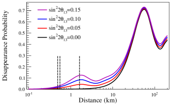
Nuclear reactors are a prodigious source of antineutrinos with energies below 10 MeV. For the antineutrino energies and propagation lengths at Daya Bay, the electron antineutrino oscillation probability is directly related to and exhibits minimal dependence on most other oscillation parameters. Over the distances and energies at Daya Bay, the probability of a reactor electron antineutrino remaining in the electron flavor state is approximated well by Equation 1 [5, 6, 7]. Figure 1 plots the exact oscillation probability as a function of distance traveled, integrated over the reactor antineutrino energy spectrum.
| (1) |
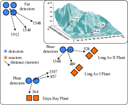
Oscillation between the Daya Bay reactors and the experimental sites reduces the electron antineutrino flux and distorts the detected spectra in proportion to the value of . Figure 1 provides the topology of the Daya Bay experiment. The two near detector sites, built to house two detectors each, are situated a flux-weighted average of about 500 m from the reactors. The far detector site, built for four detectors, is located an average distance of about 1.6 km from the reactors, near the oscillation maximum.
The strength of the Daya Bay experiment is the deployment of identical detector pairs to these near and far sites, with special emphasis on constructing identical near-far pairs. As Figure 1 illustrates, the far site maximizes sensitivity to while minimizing sensitivity to , and . While the oscillation probability depends on , the far site is located such that the event rates are equal over the range of possible values of . The near detectors make a precise measurement of the initial antineutrino flux with limited oscillation, and the powerful near-far pairing mitigates uncertainties on the reactor power and detection efficiency.
2 Daya Bay Antineutrino Detectors
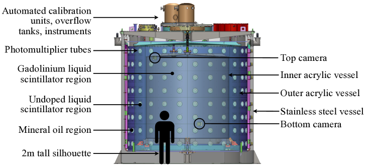
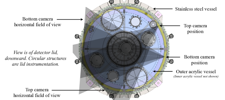
The Daya Bay antineutrino detectors consist of a 20-ton target of gadolinium-doped liquid scintillator (linear alkylbenzene) surrounded by a volume of undoped liquid scintillator, which is in turn enveloped by a nonscintillating mineral oil buffer. These liquids are contained by two concentric acrylic vessels [8] enclosed in a stainless steel vessel. The stainless steel vessel supports 192 photomultiplier tubes (PMTs), top and bottom reflectors, calibration units and multiple monitoring devices, including the cameras described in this paper. The PMTs are distributed azimuthally around the detector in conjunction with the specular reflectors at the top and bottom. Figure 2 provides a labeled cross-section of the detector including cameras.
Antineutrino detection occurs via inverse beta decay () in the target region. An incoming antineutrino reacts with a proton, generating a neutron and a positron. The positron annihilates promptly into gamma rays, while the neutron thermalizes before capturing on a gadolinium nucleus, releasing more gammas after a known delay. Thus, antineutrino events in the detectors exhibit a distinct energy and time signature, which allows excellent discrimination from backgrounds. The gadolinium in this reaction was added to the target volume for its large neutron capture cross-section, while the envelope of undoped scintillator functions to catch most gamma rays that escape from the target volume. In this manner, fiducial cuts are unnecessary to identify antineutrino events.
Two cameras are built into each antineutrino detector as an integral part of their monitoring instrumentation. These cameras provide the only visual information inside the detector, and offer vital monitoring images during construction and transportation. The cameras can also cross-check the motion of calibration sources inside the detectors as desired.
3 Goals and Design Requirements of the Monitoring Camera System

The cameras are first shown in Figure 3. They are designed to monitor many processes, including detector filling, transportation, installation and calibration, as well as to provide a flexible, on-demand investigative tool. These processes dictate the system design goals.
One of the principal uses of the camera is the monitoring of the detector liquids during filling. The goal during detector filling is to maintain equal liquid levels within 5 cm at all times as all three fluids are pumped in simultaneously, at different speeds. Although there are a variety of instruments measuring the fluid mass flow, the cameras offer the only visual verification. The system must be capable of providing live visual confirmation of all three fluid levels inside the detector, especially when the liquids reach the tops and bottoms of the acrylic vessels.
Similarly, transportation of the detectors, which occurs before and after filling, is a process that requires careful monitoring to avoid damage. The cameras must help ensure the safety of the move by displaying the position of various detector elements in real time. In addition, the system must provide a photographic record of the positions of internal components before and after filling, transport and installation, especially of the bellows that attach the inner acrylic vessels to the top of the detector, a sample of PMTs, the reflectors, and the connections at the bases of the acrylic vessels.
Detector calibration is another process of interest. The automated calibration, whereby a radioactive source is periodically lowered under gravity though the detector volumes, is a well-regulated process that nonetheless benefits from the availability of the cameras on demand. Less frequent is the manual calibration, whereby a source is inserted along an extendible, rotatable arm from a platform atop the detector. Either calibration procedure poses the risk of inserting an active source of radiation into the detector, and while the likelihood of an error is low, the consequence would be high. The camera must be capable of cross-checking the source deployment whenever desired.
Finally, the cameras must offer an effective general-purpose inspection tool. They have to satisfy the explicit list of monitoring requirements while remaining as versatile as possible, able to provide a wide, detailed view on limited notice.
3.1 Design Specifications
The cameras’ visual requirements are established by the critical features of the detector that may need to be photographed. Critical features are those that are pertinent to the monitoring tasks described in Section 3. This list includes liquid levels during filling, bellows connecting the tops of the acrylic vessels with the lid of the detector through which calibration and filling devices pass, the connections among the acrylic vessels, reflectors, and other interfaces among components. From the closest bellow to the fluid levels across the detector, the depth of field required of the cameras is 75 cm to 450 cm, and the required field of view is at least 30∘ horizontally and vertically. The design field of view is shown in Figures 4 and 5. A goal of 1 mm resolution throughout the detector is established from the features that need to be resolved finely, such as bond gaps in the acrylic, or crazing that could develop. These requirements compete with one another and force compromise. For instance, a deep field generally requires a large f-stop (a narrow aperture), but the limited available light necessitates a wide aperture. This all must be reconciled empirically.
A clear requirement of this system is that it provide its own light, since the detector is light-tight by necessity. Furthermore, this light must not interfere with the PMTs, or otherwise with data taking. As a result, the system must provide both normal white light and infrared light well outside the PMTs’ wavelength domain, and usage of both must be carefully controlled.
Equally vital, the system must meet these requirements without interfering with the operation of the detector. The materials chosen for the project must not introduce excessive radioactive backgrounds, nor chemically interact with the mineral oil buffer. The collaboration has established a radioactivity goal of 50 Hz or less per detector for energies greater than 1 MeV. Any more radioactivity risks increasing systematic uncertainties and detector dead time. Failure to use compatible materials may cause increased opacity in mineral oil or acrylic over time. The construction of the system therefore uses materials found elsewhere in the detector, assembled in a clean environment such as a nitrogen bag or a class 10000 or better clean room.
Finally, the camera system must be robustly constructed to be operable throughout the five-year expected lifetime of a detector. Repairs are impossible once the detectors are filled, so the design must be simple and resilient. Mechanical motion and unnecessary electrical components are discouraged, data lines must be reliable, and the enclosure must be leak-tight.
4 Design of the Monitoring Camera System
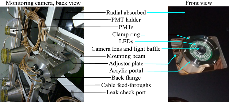
Figure 6 shows a single camera installed on a PMT ladder, the structure of vertical and horizontal beams that secure the PMTs. The visible components are labeled and discussed in this section. Together, Figures 2-6 portray the camera system in the context of the detector.
4.1 Camera and Optics
The camera chosen for this project is the small machine vision camera UI5480SE-MGL manufactured by IDS Imaging Development Systems [9], shown in Figure 7. The UI5480SE-MGL is compact and offers 5 MB resolution, infrared sensitivity, and ethernet connectivity. At 5 megapixels per image, the camera achieves the goal of 1 mm resolution across the detector with a lens of focal length 6 mm or longer. As such, the camera is not the limiting factor in resolution, but rather the dim light and the polish grade of the acrylic vessels. The camera’s infrared sensitivity [10] is sufficient to photograph the detector without white light, which Figure 7 demonstrates. In the 900 nm-1000 nm range where the quantum efficiency is not shown in Figure 7, the relative quantum efficiency is approximately half the value at 900 nm [11]. Choosing the monochrome model improves the overall sensitivity by omitting unnecessary color filters.
Since video cameras are typically not constructed for low radioactivity measurements, they can include materials otherwise too radioactive for the detectors. For instance, materials such as glass and aluminum are typically not used in low-background detectors, but are difficult to avoid in cameras and lenses. The solution is a camera with little mass enclosed in a low-radioactivity housing. At only 108 g and 40 mm a side, the UI5480SE-MGL minimizes the introduction of potentially radioactive materials and allows the housing to be small.
Since the camera is more than 50 m from the control electronics, care must be taken in the choice of readout technology for robust and reliable operation. The data are conveyed over ethernet, which is reliable and easy to integrate into the experimental halls at adequate bandwidth. This is superior to other options like USB and analog coaxial models. USB camera signals would require repeaters in sensitive locations, while cameras with analog coaxial readouts tend to offer lower resolution.
Other types of consumer and scientific cameras were considered but found unsuitable for this application. Customized versions of commercial, consumer-grade cameras have been used in other neutrino detectors such as Borexino [12, 13]. However, handheld consumer cameras generally have infrared cut filters integrated directly onto the sensor, are not equipped for ethernet transmission, and are not designed to run for long periods in isolation. Pan-tilt-zoom security cameras meet these requirements, but rely on motors that cannot be serviced in the event of mechanical failure. Finally, cameras for laser applications were highly sensitive to infrared but low in resolution.
The lens chosen for this system was the HFA0612 from Senko Advanced Components [14]. The HFA0612 is a megapixel-quality lens with an infrared transmission at 60% [15]. It is not specially constructed for infrared focus, but testing shows that the focus is adequate. A lens that is constructed for both megapixel quality and infrared light is much more expensive; in this application megapixel quality is far more important so long as infrared transmission is satisfactory. The reduced transmission is offset by the ability to take long exposures; all processes of interest are very slow, or static. The HFA0612 focal length is 6 mm, which offers both the resolution and field of view desired, while the lens has an adjustable iris that allows the f-stop to be optimized experimentally. Due to the counterplay between the wide depth of field desired and the limited light, finding the best iris diameter empirically is crucial. Lens types that were considered but rejected include varifocal and plastic varieties. Varifocal lenses, for which the focal length can be adjusted electronically, have mechanical parts that risk failure. Plastic lenses, which would have been less radioactive, were not available at the desired resolution.

4.2 Lighting
Since Daya Bay’s antineutrino detectors detect single photon signals, the detectors must be light-tight, and the camera system must supply its own controllable source of illumination. This source must not interfere with the PMTs, but must provide sufficient light to resolve important features across the detector. It must also be regulable so that a user can optimize the illumination to resolve a particular feature. Finally, the light must not backscatter off the acrylic into the camera, cause blinding fluorescence in the scintillator, nor create more heat than can be dissipated by the enclosure.
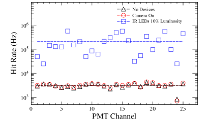
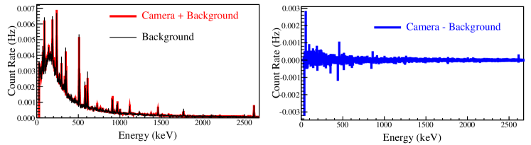
In this system, the light is provided by an array of 120 infrared and 60 white LEDs encircling the lens, shown in Figure 8. The infrared LEDs are the model VSLB3940 from Vishay [16], which shine at central wavelength 940 nm. Figure 7 juxtaposes the LED spectrum with the quantum efficiency of the PMTs [17] and camera. Infrared LEDs allow the camera system to run in a manner compatible with PMTs, as required anytime the detector will be operated soon after illumination, or could be powered by user error. The consequence of running the infrared LEDs when the PMTs are powered is minimal because the PMT response drops sharply at about 700 nm. The hit rates will increase, as shown in Figure 9, but will return to their normal baseline quickly. Data is not taken when the infrared LEDs are on, and the data acquisition system is suspended out of precaution. It is worth noting that dark box tests of infrared LEDs and PMTs differ from tests in the detector. The dark box PMTs do not show this increase in hit rates from infrared light, so it is suspected that the hit rate increase is influenced by surrounding material.

The effect of white light on PMTs is understandably greater. When the PMTs are unpowered, illumination with the white LEDs is preferable. White light shone on unpowered PMTs still causes an increase in dark rates for a period of time less than 24 hours afterward, but no long-term effects. The 60 white C513A-WSN LEDs from CREE [18] are brighter, more efficient and illuminate within the optimal quantum efficiency of the camera and lens. They therefore generate less heat than the infrared LEDs. At maximum luminosity, the 60 white LEDs draw 5 W of power while the infrared LEDs draw 16 W.
The white LEDs easily illuminate the detector. The attenuation length in the visible-near infrared range of each optical medium is longer than 10 m, and the liquid scintillator only absorbs in the near ultraviolet range. Thus the liquids and acrylic neither obstruct much light nor fluoresce back into the camera. The indices of refraction off the acrylic vessels and liquids are constant from the near ultraviolet to the near infrared, so the passage of light through the acrylic and scintillating media is unimpeded
The LEDs shine through a specially designed portal that passes light without any reflections back into the lens, shown in Figure 8. When the detector is unfilled, backward reflections of the LED light of the enclosure’s acrylic portal would decrease the cameras’ effectiveness. To prevent glare, two baffles are embedded into the acrylic portal, and the lens is pressed into a black foam annulus perpendicular to them. The arrangement successfully obstructs all glare from the lens.
Finally, both white and infrared LEDs are interlocked in software to prevent them from being activated when the PMT high voltage is on, and the LED power cables are unplugged and locked out when not in use. This is discussed in Section 4.4.
4.3 Integration into Detector
The camera housings mount onto the PMT ladders that supports the detectors’ PMTs, black absorbing shields and some sensors. The housings are fixed within an adjustable, stainless steel mount that permits three translations and two rotations. At the front of the enclosure is an acrylic portal through which the camera and LEDs face the detector. At the back, a leak-tight flange conducts five cables. All materials that contact the mineral oil buffer in which the system resides are either stainless steel, acrylic, nylon, viton, or Teflon: compatible materials used elsewhere in the detectors. The enclosure and mounting are illustrated in Figure 10.

The front portal allows clear imaging and illumination of the detector while withstanding its fluid pressure. The half-inch thick acrylic presses against two o-rings and the front flange of the enclosure body. A clamp ring in front of the acrylic maintains pressure on the o-rings without damaging the acrylic. The portal is not a perfect circle: two short chords are cut off the portal, back flange, and o-ring flanges to improve clearance for installation. The two concentric, opaque light baffles described in Section 4.2 sit tightly in opposing grooves cut 3/8” deep and 1/16” wide.
The camera itself is positioned against the portal along a rod that attaches to the back flange. The rod offers adjustability of the camera position and effectively dissipates heat into the mineral oil buffer and PMT ladder. The back flange attaches to the enclosure like the portal, and passes five coaxial cables that conduct electrical power and data to and from the camera and LEDs, as discussed in Section 4.4.
The cables are sealed by a feed-through plug that is identical to that used for the PMTs. Each cable is produced with captured seal plugs on both ends. Within each seal plug, a hollow bolt compresses two o-rings against the cable and inner seal plug. Two more o-rings compress against the seal plug and matching hole in the flange when the plugs are pushed into place and captured by a retaining ring. Overall, the enclosure contains the camera, LEDs and electronics in a leak-tight volume.
The enclosure attaches to the PMT ladder by way of an adjustable mount that allows several degrees of freedom. The mount and enclosure are connected by three ball and socket joints formed from round indentations on a flat plate welded onto the enclosure. Three threaded rod-ball bearing assemblies sit in these indentations, held by three smaller capture plates and shims, with the threaded rods extending through an adjustor plate. The capture plates and shims hold the threaded rods fast, but allow slight movement of the joints to prevent tension. The adjustor plate has one clearance hole serving as a pivot point, and one continuous arc. The arc permits the camera to pan, while nuts on the threaded rods allow independent pitch and height adjustment. Once the position is set, pairs of nuts lock the configuration into place.
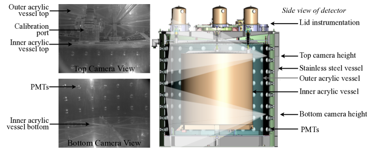
The cameras are installed on adjacent ladders in voids between rows of PMTs, one just below the top row, the other above the second row from the bottom. These positions are indicated in the detector diagrams of Figures 2, Figures 4 and 5 The positions and orientations of the cameras are chosen to maximize the usefulness of the view. The top camera is pitched upward 6∘ and panned 7∘ counterclockwise relative to a vertical downward axis, to visualize the most critical features, such as the bellows and liquid levels at the tops of the acrylic vessels. The bottom camera is pitched downward to view more low lying features of the detector such as the bottom reflector and acrylic vessel connections. The cameras are shown at various stages of installation in Figure 11.

4.4 System Readout and Control
The control system is designed amid constraints imposed by the detectors and other electronics, particularly regarding materials compatibility, leak-tightness, electronic noise and inaccessibility. The camera requires an ethernet data connection and direct current power, while the LEDs also require direct current power. Typical cables for power and ethernet are barred from the detectors due to materials compatibility, so the system uses BNC coaxial cables identical to those of the PMTs for these purposes. These cables are Teflon coated and form leak-tight seals with the existing Daya Bay seal plugs. Many non-coaxial cables, especially ethernet, lack the uniform surface required for this seal to be leak-tight.
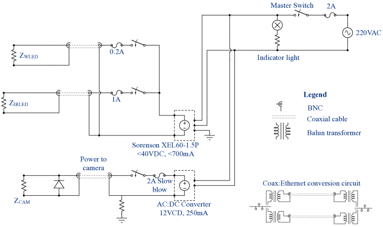
Signals sent to and from the camera are converted between ethernet and coaxial cables by way of balun transformers. The baluns have a 2:1 impedance ratio to match the 50 coaxial cable to the 100 ethernet. Inside the enclosure two baluns convert two ethernet twisted pairs to two coaxial cables, while another pair inside the readout box reverses the conversion (Figure 12). A balun creates an unbalanced signal from the balanced, positive and negative pulses along the ethernet. While the unbalanced signal is inherently more susceptible to noise, the coaxial cable is sufficiently shielded. The bandwidth is reduced from the 1 Gbps maximum of the camera to 100 Mbps, but this is more than sufficient to operate the camera within demands. Since the subjects of the camera are very slow processes or stationary objects, and since the camera operates in a low light environment, the frame rate is set as low as permitted– 0.29 fps– and the bandwidth used is far lower than 100 Mbps.
In total there are five coaxial cables: three conducting power to the camera, white and infrared LEDs, and two transmitting data to and from the camera. Alternatives for fewer cables were considered and rejected for fear of superfluous components inside the detector, which increase the risk of radioactive backgrounds, heat production, and inaccessible component failures.
In addition to converting the signal to ethernet, the readout system contains an ethernet-controlled relay bank and power supplies managing a total of four cameras. DC power to all cameras and LEDs passes through the 16-switch relay bank, model NER165PROXR [19] from National Control Devices, which selects one camera and one light source to operate. The power supply for the LEDs is a single programmable Sorenson XEL 60-1.5P [20], and the power source for the cameras and relay bank are AC:DC converters provided by the manufacturers. The readout box also contains an array of fuses and indicator lights for safety. The relay bank and power supply were chosen for their ethernet connectivity, programmability, and ease of integration into the control software.
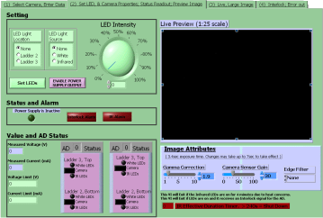
The operating software plays an important role in both running the cameras and protecting the detector and camera system. The LabView-based [21] interface operates the system by controlling the relay card, power supply and camera over the network. The power supply and relay are represented in software as Virtual Instrument Software Architecture (VISA) resources. Custom code using drivers provided by the devices’ manufacturers is integrated into the experiment’s comprehensive control framework.
The user is permitted to operate one of four cameras in a pair of detectors at a time, within the built-in safety constraints. The system is configured to preclude the operation of the wrong camera, and will not summon power to LEDs outside acceptable voltage and current ranges. Meanwhile, if the PMT high voltage is active, the LEDs are interlocked. Also, since the infrared LEDs generate 16 W of power pressed against the poorly dissipating acrylic surface, the user is time-limited in their usage. Otherwise, the user has control over LED brightness and camera gain, and can select one camera out of four connected with either type of LED at either position in the same detector. Only one LED strand is permitted power at a time to prevent too large a current through the system. For best results, when the detector is dry, the user relies on the LEDs from the opposite camera position, taking advantage of the light scattering about the acrylic and reflectors. After filling, the user should illuminate the LEDs of the same camera. The user can capture images manually or automatically at a selected rate, and the images are immediately uploaded to a central database.
5 Background Levels
The radioactivity of one complete camera assembly was measured, and the activity from most isotopes is consistent with zero (Table 1, Figure 14). Those isotopes with nonzero activity are members of the 232Th decay chain, primarily 228Ac. In total, one camera assembly has a similar level of activity to one Hamamatsu R5912 PMT, and the largest sources of activity are presumed to be the glass in the lens and circuit board, and the aluminum comprising the camera case.
| Chain | Nuclide | Line | Camera Activity | PMT Activity | |||
| (keV) | (Bq) | (Bq) | |||||
| 0.66 | 2.05 | 3.9 | |||||
| 228Ac | 911.07 | 2.5 | 0.77 | ||||
| 968.97 | 0.737 | 1.13 | |||||
| 212Pb | 238.63 | 0.825 | 0.43 | ||||
| 208Tl | 583.14 | 0.0957 | 0.216 | ||||
| 2614.47 | 0.408 | 0.315 | |||||
| Total | 0.912 | 0.57 | 0.6 | ||||
| 214Bi | 608.81 | 0.45 | |||||
| 1764.24 | 1.37 | ||||||
| 214Pb | 294.83 | 0.82 | |||||
| 352.59 | 0.52 | ||||||
| Total | 0.79 | 1.9 | |||||
6 Performance
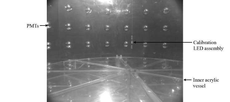
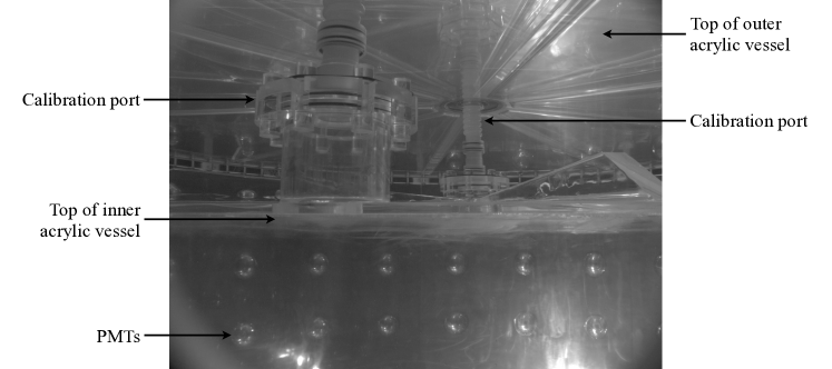
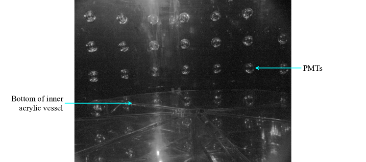
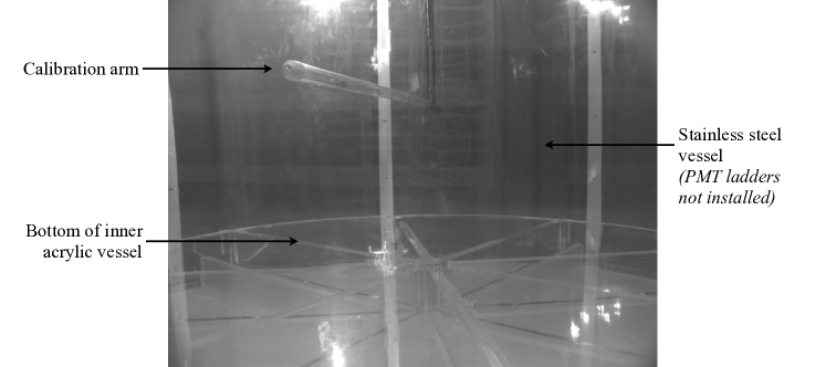
The cameras have proven very useful and reliable, providing an average of 2,000 images per detector. Most of these images were taken during the filling process, followed by monitoring of detector transportation. Figures 15 and 16 show annotated photographs taken using the bottom camera and white light from the top camera, during an automated calibration test, and detector filling respectively. The calibration source and liquid levels appear very clearly. Figure 17 shows a photograph taken from the top camera in a dry detector with white light from the bottom camera, while Figure 18 shows a photograph taken after filling, using white light from the same camera. As an example of infrared light photography, Figure 19 displays a photograph of the inside of a dry detector taken with the bottom camera under infrared light from the opposite camera. Finally, Figure 20 shows an image of a manual calibration mechanical test in a partially assembled detector, taken under with the bottom camera white light from the top camera.


7 Summary
The cameras have proven to be a vital component in building and maintaining the antineutrino detectors for the Daya Bay experiment. All together they have captured over 10,000 photographs during the filling, transportation and calibration procedures, without interference with data collection. The system was effectively designed around several constraints imposed by the arrangement of features within the detector, materials compatibility, radioactive backgrounds, electronics and light interference. The designs presented in this article are useful for the design of any camera system or similar low-background application.
Appendix A Acknowledgments
We gratefully acknowledge support from the Department of Energy Office of Science, High Energy Physics, under contract DE-FG02-95ER40896 and support of the University of Wisconsin Foundation. We thank the Kellogg group at the California Institute of Technology and their HPGe radioassay facility, as well as the Low Background Facility at Lawrence Berkeley National Laboratories, for measuring radioactive backgrounds of the camera system. We thank Jesse Nims and Ruxiu Zhao for assistance in assembling cameras; Amy Pagac and Al Riley for providing drawings; Billy J. Gates Jr., Daniel Wahl and Harold Mattison for advice regarding electronics; Zhimin Wang, Dan Dwyer, Hu Tao, Cheng-Ju Lin, Kam-Biu Luk and Johnny Ho for assistance in testing PMT hit rates under infrared light; and Julio De Oliveira for help with evaluating cameras.
References
- [1] Daya Bay Collaboration, X. Guo et. al., A precision measurement of the neutrino mixing angle using reactor antineutrinos at Daya Bay, hep-ex/0701029.
- [2] Daya Bay Collaboration, F. An et. al., Observation of electron-antineutrino disappearance at Daya Bay, arXiv:1203.1669.
- [3] Daya Bay Collaboration, F. An et. al., A side-by-side comparison of Daya Bay antineutrino detectors, arXiv:1202.6181.
- [4] China Guangdong Nuclear Holding Company. Jinyu Building, No.100 North Road, West 3rd Ring, Beijing, China, 100048, http://www.cgnpc.com.cn.
- [5] Z. Maki, M. Nakagawa, and S. Sakata, Remarks on the unified model of elementary particles, Progress of Theoretical Physics 28 (1962), no. 5 870–880.
- [6] B. Pontecorvo, Neutrino experiments and the question of leptonic-charge conservation, Sov. Phys. JETP 26 (1968) 984–988.
- [7] V. Gribov and B. Pontecorvo, Neutrino astronomy and lepton charge, Phys.Lett. B28 (1969) 493.
- [8] H. R. Band et. al., Acrylic Target Vessels for a High-Precision Measurement of theta13 with the Daya Bay Antineutrino Detectors, arXiv:1202.2000.
- [9] IDS Imaging Development Systems GmbH. Dimbacher Strasse 6-8 D-74182 Obersulm, Germany, http://www.ids-imaging.com/index.php.
- [10] Aptina Imaging. http://www.aptina.com.
- [11] Aptina Imaging. Private correspondence.
- [12] Borexino Collaboration, G. Alimonti et. al., Science and technology of BOREXINO: A Real time detector for low-energy solar neutrinos, Astropart.Phys. 16 (2002) 205–234, [hep-ex/0012030].
- [13] H. O. Back, Internal radioactive source calibration of the Borexino solar neutrino experiment. PhD thesis, Virginia Tech, Blacksburg, Virginia, 2004.
- [14] SENKO Advanced Components, Inc. 225 Cedar Hill Street Marlboro, MA, USA 01752, http://www.senkoadl.com.
- [15] SENKO Advanced Components, Inc. Private correspondence.
- [16] Vishay Intertechnology Inc. One Greenwich Place Shelton, CT, USA 06484 United States, http://www.vishay.com.
- [17] Hamamatsu Photonics, Electron Tube Division. 314-5 Shimokanzo Iwata City, Shizuoka Pref., Japan, http://www.hamamatsu.com/.
- [18] Cree, Inc. 4600 Silicon Drive Durham, NC, USA 27703, http://www.cree.com.
- [19] National Control Devices, LLC. PO Box 455 Osceola, MO, USA 64776, http://www.controlanything.com.
- [20] AMETEK Programmable Power, Inc. 9250 Brown Deer Road San Diego, CA 92121, http://www.sorensen.com.
- [21] National Instruments Corporation. 11500 N Mopac Expwy Austin, TX 78759-3504, http://www.ni.com.