The Jefferson Lab Frozen Spin Target
Abstract
A frozen spin polarized target, constructed at Jefferson Lab for use inside a large acceptance spectrometer, is described. The target has been utilized for photoproduction measurements with polarized tagged photons of both longitudinal and circular polarization. Protons in TEMPO-doped butanol were dynamically polarized to approximately 90% outside the spectrometer at 5 T and 200–300 mK. Photoproduction data were acquired with the target inside the spectrometer at a frozen-spin temperature of approximately 30 mK with the polarization maintained by a thin, superconducting coil installed inside the target cryostat. A 0.56 T solenoid was used for longitudinal target polarization and a 0.50 T dipole for transverse polarization. Spin-lattice relaxation times as high as 4000 hours were observed. We also report polarization results for deuterated propanediol doped with the trityl radical OX063.
keywords:
frozen-spin target , polarized target , dilution refrigerator , internal holding coil1 Introduction
One of the major research initiatives taking place in Hall B at Jefferson Lab is the NSTAR program, the experimental study of baryonic resonances. Despite decades of electron, meson, and photo-production studies, a complete and well-characterized spectrum of excited baryonic states remains missing. The parameters of many resonances (such as their mass, width, and decay couplings) are not well known, while other resonances, predicted by various QCD models, have yet to be experimentally verified. Experiments with both polarized beam and polarized target are critical to disentangling this complex spectrum of broad, overlapping resonances [1]. Of particular importance are experiments that combine multiple combinations of beam and target polarization. In this article we describe a frozen spin polarized target explicitly constructed for such experiments inside a large acceptance spectrometer. The target can provide either longitudinal or transverse polarization, depending on the choice of magnet used to maintain the polarization.
The centerpiece of the Hall B instrumentation package is the CEBAF Large Acceptance Spectrometer (CLAS), a multi-gap, high-acceptance magnetic spectrometer in which the field is generated by six superconducting coils in a toroidal configuration [2]. This coil arrangement leaves a field-free region in the center of the detector that is well suited for the insertion of a polarized target. One such target, dynamically polarized by continuous microwave irradiation at 140 GHz, has been previously described [3] and has been used inside CLAS with electron beams up to 10 nA. However, this target features a 5 T superconducting magnet whose geometry limits the acceptance for scattered particles to in the forward direction, whereas the acceptance of CLAS spans . Furthermore, the magnetic field is by necessity parallel to the beam line and can therefore provide only longitudinal polarization.

To compliment the existing polarized target in Hall B, we have designed and constructed a frozen spin target, FROST, which permits the detection of scattered particles over an angular range of . The target has been utilized on two separate occasions, each lasting about six months. It was longitudinally polarized during the first set of experiments (g9a), and transversely polarized for the second (g9b). Both circularly and linearly polarized photon beams were used during g9a and g9b, so taken together, all four possible combinations of beam and target polarization were realized, resulting in a so-called “complete” experiment.
The remainder of this article is organized as follows. A general overview of the target system and its operation is given in Section 2, with more detailed descriptions of the various components provided in Section 3. Its performance during both experiments is described in Section 4, and a summary is made in the final section.
2 System Overview
The operation of the frozen spin target is depicted schematically in Fig. 1. The target sample is polarized with microwaves via Dynamic Nuclear Polarization (DNP) in the bore of a high field, high homogeneity magnet. The microwaves are then switched off, the target is cooled to a temperature below approximately 50 mK, and the polarization is maintained by a weaker magnetic field. In our case this field is produced by a small superconducting magnet installed inside the target cryostat. The scattering data is acquired while the target polarization decays in an exponential manner with a spin-lattice time constant that is determined in part by the temperature of the material and the strength of the magnetic field. The DNP process is repeated when the polarization has fallen to an unacceptably low value or to change the direction of the polarization.
The major components of FROST, which we describe in the following section, are:
-
1.
a 5 T polarizing magnet with a horizontal warm bore;
-
2.
a bespoke, horizontal 3He-4He dilution refrigerator (DR) with a high cooling capacity;
-
3.
a novel vacuum seal and insertion device for loading the target material directly into the mixing chamber of the DR;
-
4.
one of two internal superconducting holding coils;
-
5.
a 140 GHz microwave system for the DNP process;
-
6.
a continuous-wave, nuclear magnetic resonance (CW-NMR) system for measuring the polarization.
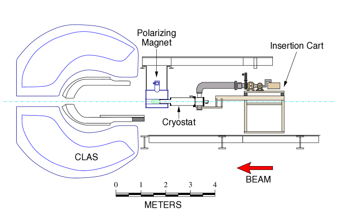
The layout of the system is shown in Fig. 2. The target cryostat is suspended from the lower portion of a two-tiered insertion cart that is mounted on rails for travel into the center of the spectrometer. Most of the vacuum pumps for the cryostat are mounted to the upper tier, which is vibrationally isolated from the lower tier by four air springs. A control panel for the pumps, electronics for monitoring and controlling the target, and two gas panels for the DR are also mounted to the lower tier. Only a large chiller for water-cooled vacuum pumps and two tanks for storing the 3He-4He mash are not mounted to the insertion cart. These items are located on Level 2 of the steel frame surrounding the spectrometer, and connect via flexible lines to the target on Level 1 below. The polarizing magnet is suspended at the entrance to the spectrometer from a set of rails perpendicular to the beamline, and can be moved approximately 1 m in the beam-left direction, allowing the target cart to be moved to the center of CLAS.
The polarization process begins with the target cryostat inserted into the bore of the polarizing magnet (at 5 T) and the microwave tube energized. The time required to reach 80% proton polarization is about 2–3 hours, and another 3 hours are necessary to reach 90–95%. During this time the microwaves (50–100 mW) warm the target sample to about 0.3 K. The field of the polarizing magnet is parallel to the beamline, and so the target is longitudinally polarized. After the microwaves are switched off, 30–45 minutes are required for the target to cool to a temperature less than 50 mK. At that time the polarizing magnet is de-energized, while the internal holding magnet is simultaneously energized at a rate that maintains a net magnetic field of about 0.5 T (another 45 minutes). The direction of the polarization either remains longitudinal, or is rotated transverse to the beam, depending on which holding coil is installed inside the target cryostat.
The cryostat is then retracted from the polarizing magnet, the latter is moved out of the way, and the cryostat is moved approximately 4 meters into the center of CLAS (about 2 minutes) where it continues to cool below 30 mK. The tagged photon beam is activated and photoproduction data is acquired for a period of 5–10 days, after which the polarization process is repeated, usually to reverse the target polarization. The photon beam deposits 10–20 W to the refrigerator, warming it 2 mK or so. Even with beam on target, the polarization loss is only about 1% per day.
3 Components of FROST
3.1 Polarizing Magnet
A 5 Tesla solenoid222Cryomagnetics, Inc. was used during the DNP process to polarize the target material. The solenoid has a horizontal, room-temperature bore of 127 mm diameter and produces a maximum field of 5.1 T at 82.8 A. The inhomogeneity of the solenoid’s central field is over the volume of our sample, a 50 mm long, 15 mm diameter cylinder. It features a 45 l volume for liquid helium and two vapor-cooled heat shields, obviating the need for liquid nitrogen. Using a flexible transfer line, the magnet was automatically filled with LHe about every 4 days from a nearby 500 l dewar. Liquid in the dewar was continuously replenished from Jefferson Lab’s End Station Refrigerator, or ESR.
3.2 Dilution Refrigerator
To aid in the following discussion, a flow diagram for the frozen spin target is shown in Fig. 3, while a sectional view of the target is given in Fig.4. There are two quasi-independent refrigeration systems inside the target cryostat: a 3He-4He dilution refrigerator and a 4He evaporation refrigerator, also called the precooler. To conserve space, the precooler is located inside the 180 mm diameter tube that is used for pumping 3He from the dilution unit. It is sealed inside this pumping tube using an indium seal at one end and a rubber o-ring at the other. Both refrigeration units are constructed around a separate, thin-walled stainless tube that is 50 mm in diameter in the case of the precooler, and 40 mm for the dilution refrigerator. These bolt together using commercial knife-edge flanges, forming a single tube that extends from room temperature at one end to the mixing chamber at the other. This tube serves as both an evacuated beam pipe for the photon beam, and as a load-lock tube for inserting the polarizable target sample into the mixing chamber. At the room temperature end, the tube is sealed with a 0.13 mm thick polyimide beam-entrance window. The opposite end is sealed by a 0.13 mm thick aluminum window on the sample insertion device described in Section 3.3.
As its name implies, the precooler’s purpose is to cool and condense 3He before it circulates through the dilution unit. It consists of two counterflow gas-gas heat exchangers, and two 1 liter vessels, or “pots”, containing liquid helium at 4 K and 1 K, respectively. Both pots are welded around the central beam pipe and are instrumented with RuO temperature sensors and miniature superconducting level probes. The 4K pot is continuously filled with LHe from the same 500 l dewar that services the polarizing magnet. Vapor is pumped from this pot along two paths. The first is used to cool incoming 3He via heat exchanger HX1, while the second cools both a 20 K heat shield surrounding the refrigerator as well as a copper plate that is located in the upstream end of the target and used to heat sink all tubes, wires, and cables as the enter the cryostat. The 1K pot receives liquid helium from the 4K pot via needle valve NV1. Vapor pumped from this pot is also used to cool 3He gas using heat exchangers HX1 and HX2. The 3He gas is condensed inside the 1K pot using HX3, the condenser.

HX1 consists of three, thin-walled stainless tubes welded coaxially around the beam pipe. The tubes are approximately 80 cm long with annular gaps between one tube and the next of 0.25, 1, and 2 mm. Cold helium gas from the 1K and 4K pots is pumped through the inner and outermost gaps, while incoming 3He flows in the central gap. In this manner the 3He exchanges heat with gas from both the 4K and 1K pots and is cooled to about 3K. HX2 consists of a 19 mm diameter, 40 cm long tube for low pressure gas pumped from the 1K pot. A pair of 3 m long, 3 mm diameter tubes are coiled tightly inside and carry liquid helium from the 4K pot and 3He from HX1. The condenser is a 10 cm3 copper cup, filled with sintered 50 m copper powder and located inside the 1K pot. The 3He condensation pressure is set by needle valve NV2, located downstream of the condenser. A third needle valve, NV3, bypasses both HX2 and the condenser to deliver cold 3He gas directly to the mixing chamber. This valve is used only for initially cooling the dilution unit from room temperature and is closed during normal operation.
Two small diaphragm pumps are used to pump vapor from the 4K pot, while a 120 m3 h-1 roots system is used for the 1K pot. All gas pumped from the precooler is returned to the End Station Refrigerator for liquefaction.
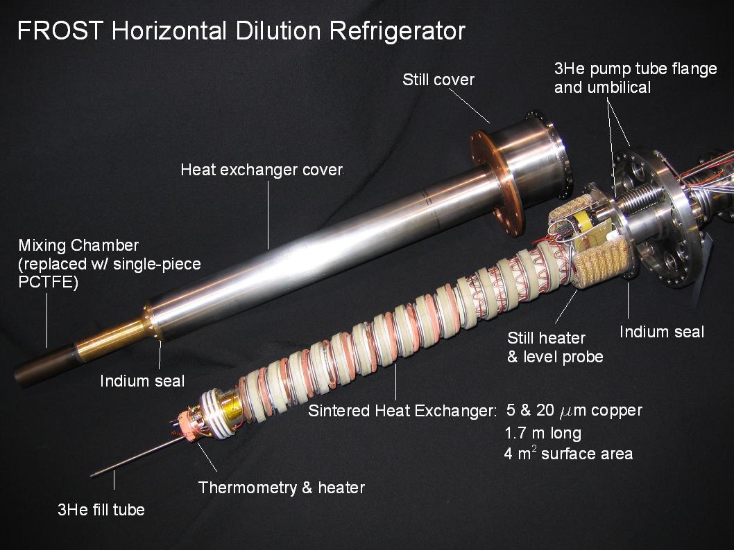
The dilution unit consist of the customary still, heat exchanger, and mixing chamber. It is located downstream of the 180 mm pumping tube and is surrounded by the 20 K heat shield. A second heat shield, at 1 K, is attached to the still and surrounds both the heat exchanger and mixer. Both heat shields are constructed of copper with 1 mm thick aluminum extensions around the mixing chamber. A photograph of the DR is shown in Fig. 5.
The still is constructed from a 100 mm diameter stainless steel tube which seals with an indium o-ring against a circular flange welded around the central beam pipe. It is instrumented with thermometers, a heater, a capacitive liquid-level meter, and 1 m long, 1.5 mm diameter heat exchanger (HX4) for condensing any 3He that may vaporize after expanding though NV2. The heater is a 10 m long coil of 0.6 mm NiChrome wire. The level probe consists of two copper-clad fiberglass plates with a separation of 0.5 mm, and the capacitance between the plates is measured using an AC bridge circuit.
Gas from the still is pumped through a short, flexible bellows of 16 mm inner diameter connecting the top of the still to the 180 mm diameter pumping flange. All wiring for the DR, along with the 3He bypass and 3He condenser lines, pass through this bellows, or “umbilical”. 3He is pumped from the still by two dry pumping systems operating in parallel. Each system consists of Alcatel RSV2000 and RSV600 roots pumps and an Edwards L70 dry pump, and the measured pumping speed for helium is 3300 m3/hr. The 3He gas panel features two liquid nitrogen traps for filtering contaminates from the circulating gas (the second trap is a spare), but thanks to the all-dry pumping system, the trap has blocked only once, despite months of continuous use. The contaminates on that occasion were traced to a room-temperature gas fitting that had presumably vibrated loose.
The main heat exchanger for the DR (HX5) is modeled after a design by Niinikoski [4] and is comprised of three sections. The first is a 2 m length333Later shortened to 1 m, see Section 4.1 of cupronickel tube with an inner diameter of 0.5 mm. This serves as a secondary flow impedance for the circulating 3He and was added after the refrigerator experienced flow and temperature instabilities during early tests. The second section of the heat exchanger is a 1.5 m long stainless steel tube of 1.0 mm inner diameter with copper fins brazed to the outside.444Fin Tube Products, Inc. The final section of heat exchanger is comprised of six copper C122 tubes with copper powder sintered inside and out. Each tube is 28 cm long, with inner and outer diameters of 3.3 and 4.0 mm. The sinter on the outside is 1 mm thick, while the inside is filled with sinter except for a central, 1.5 mm diameter flow channel for the concentrated 3He stream. The warmest two sections are sintered with 325 mesh copper powder (nominal size 20 m), while 5 m powder was used on the coldest four. The total surface area of the sintered heat exchanger is about 4 m2 on the concentrated side and 7 m2 on the dilute side, based on 77 K measurements of argon gas adsorption.
All sections of the heat exchanger are wound in a spiral groove machined in a G10 fiberglass mandrel. The groove is 3.5 m long and has a 13 mm wide, 7 mm deep rectangular cross section. All wires to the mixing chamber and the 3 mm bypass tube are also wound in this groove. The G10 mandrel slides tightly over the central beam pipe and is covered by a second tightly-fitting stainless steel tube that attaches to the still at one end and to the mixing chamber at the other. The mixing chamber is a 1 mm thick PCTFE cup that seals against this tube using an indium o-ring. Concentrated 3He enters the mixing chamber through a PTFE tube located in the lower half of the mixer, directly under the target sample. A series of holes are punctured along the length of the tube and distribute the concentrate evenly as it rises past the sample and collects at the top of the mixer. A series of three spring-energized PTFE radial seals constrains the excess concentrate to the top half of mixing chamber, while 3 mm holes under the seals allow 3He to be removed from the dilute phase in the lower half.
The mixing chamber is outfitted with a small nichrome heater for cooling power measurements and three RuO resistance thermometers. One thermometer,555Lakeshore RX-202-AA has a room temperature resistance of 2 k and is calibrated 0.05–40 K. However, its resistance versus temperature dependence is too steep to permit accurate extrapolation to lower temperatures. The additional two resistors666Dale 1 k RCW-575 were chosen because they are known to exhibit a well-behaved, log(Tn) response at temperatures as low as 25 mK [6] and are calibrated against the first thermometer. One of these is located in the center of the mixing chamber, near the polarized target sample, while the other is in the downstream end of the heat exchanger, in the dilute flow stream. All temperatures quotes in this article are based on this last sensor as it is believed to measure the average temperature of liquid exiting the mixing chamber. The thermometers in the mixing chamber and in the still are read by a Lakeshore Model 370 AC resistance bridge, which is also used to power both the still and mixing chamber heaters.
Both the dilution and precooling refrigerators are housed inside a custom-built, stainless steel vacuum chamber. The downstream end of the chamber is made of closed-cell foam to reduce the energy loss of particles scattered from the polarized butanol sample. A thin layer of aluminum is glued to the foam’s interior surface to decrease outgassing, and a 25 m thick aluminum exit window is glued to its downstream end.
3.3 Target Material and Insert
Frozen beads of butanol (C4H9OH) were used for the target material. The butanol was doped with the nitroxyl radical TEMPO7772,2,6,6-Tetramethylpiperidinyloxy at a concentration of spins cm-3 for dynamic polarization. Water (0.5% by weight) was added to the solution before freezing in order to avoid a crystalline solid. The 1–2 mm diameter beads were formed by dripping the solution through hypodermic needles into a bath of liquid nitrogen. The needles were held at an electrical potential of approximately 2 kV in order to control the bead size. This also provided the beads with a slight static charge which kept them from clumping together in the liquid nitrogen bath.
Approximately 5 g of beads were loaded under liquid nitrogen into a 15 mm diameter, 50 mm long PCTFE target cup that attached to end of a 25 cm long stainless steel tube. The tube is sealed at the target end by a 0.13 mm thick aluminum vacuum window that also features a locking mechanism for the PCTFE cup. At the opposite end, a flange for a novel vacuum seal (described below) is welded to the tube. The cup has a number of 0.5 mm wide grooves machined into its underside which allows some of the 3He concentrate entering the mixing chamber to penetrate directly into the cup. Since 3He absorbs heat when it dilutes into liquid 4He, we believe this may provide a more efficient cooling path to the target beads.
We have developed a new superfluid-tight vacuum seal for quickly loading the target material into the mixing chamber of the dilution refrigerator while at cryogenic temperatures. Patterned after VCR face-seal fittings,888Swagelok, Inc. it features a 0.6 mm high, toroidally-shaped ridge on the insert face for compressing a polyimide vacuum gasket. A threaded nut is used to screw the insert against the cryostat-side sealing face which has a polished, conical sealing surface and male threads. The conical design ensures that thermal contraction continues to tighten the seal after the warm insert (80 K) is screwed into the cold cryostat (10 K). A set of bearings between the insert’s face seal and its threaded nut prevents the insert from rotating while the nut is turned.
The seal is made by attaching the target insert, under liquid nitrogen, to a 2 m long pipe that acts as a long wrench. This pipe has a set of retractable pins that lock into matching holes in the insert. We load the insert into the empty mixing chamber at a temperature of about 10 K with a strong helium purge on the beam pipe. After making the seal, the pins are retracted and the wrench is removed. A set of three 13 m thick aluminum heat shields is placed inside the beam pipe which is then evacuated and circulation of the 3He-4He mixture through the dilution refrigerator is begun. The entire procedure requires about 90 minutes, during which the mixing chamber temperature rises to about 60–70 K.
We have tested several gasket materials and have found that 180 m thick polyimide gives the most reliable results. We have made the seal several dozen times with almost 100% success. Leaks are almost always due to contaminants such as moisture on the gasket or threaded surfaces. These contaminants are reduced by establishing a separate helium purge on the insert as soon as it is removed from the liquid nitrogen bath.
In addition to the polarized butanol sample, two additional targets were installed in the cryostat and were used for background and dilution studies. A 1.5 mm thick carbon disk and a 3.5 mm thick CH2 disk were mounted on the 1K and 20K heat shields, approximately 6 cm and 16 cm downstream of the butanol sample.
3.4 Holding Coils
In the first generation of frozen spin targets, the holding field was generated by the fringe of the polarizing magnet or by a second, external magnet with a larger aperture. The field uniformity in these cases was not sufficient to resolve the NMR line of the target material, and so it was not possible to monitor the target polarization during the scattering experiment. Niinikoski first described a thin superconducting solenoid mounted inside the target cryostat for maintaining or rotating the target polarization [5], while the group at Bonn were the first to implement this type of solenoid in an actual experiment [7]. With careful design, these coils can be thin enough for reaction products to pass through with acceptably low energy loss and uniform enough for precise NMR measurements.
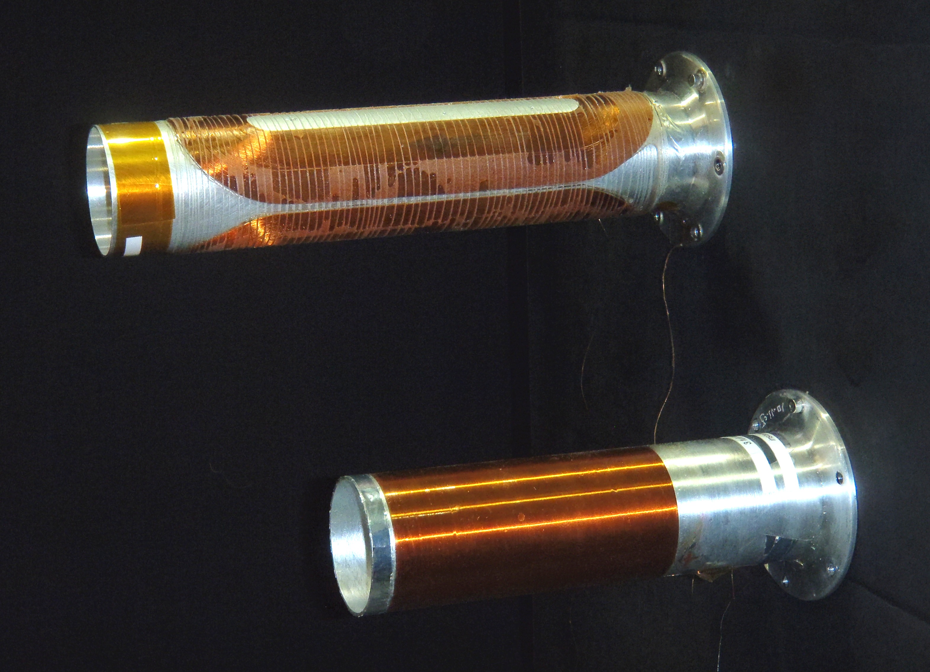
We have utilized two such coils for the g9a and g9b experiments, as shown in Fig. 6. For g9a, a 110 mm long solenoid was used to maintain longitudinal polarization. It consists of three layers of 0.14 mm copper-clad, multifiliment NbTi wire999Supercon, Inc. type 54S43. wound on a 50 mm diameter, 1 mm thick aluminum former. Each layer has 785 windings, while an additional 162 turns are added at both ends to improve the field uniformity. Grooves machined in the former aid in the placement of the windings. Stycast epoxy 1365-65N was used to adhere the coil, which produces a 0.56 T central field at 22.0 A. The aluminum former was attached to the downstream end of the 1 K copper heat shield which was in turn thermally sunk to the still.
The second coil, used for g9b, was wound as a four layer, saddle-shaped dipole. The two innermost layers each consist of 170 turns of wire, while 152 and 60 turns were used for the third and fourth layers, respectively. All eight coils were wound from a single, continuous length of 0.18 m diameter superconducting wire using a custom-designed aluminum fixture coated with PTFE. The coils were glued to a 5 m polyester backing to prevent the layers from separating as they were wrapped around and epoxied to an aluminum former similar to the one described above. In addition, a thin nylon thread was wrapped around the coils to further secure them to the former. This magnet has demonstrated a maximum field of 0.54 T, and was operated at 0.50 T (35.5 A) during g9b. The technique and equipment for winding this dipole were developed and built at Jefferson Lab for FROST, and later used to construct similar coils for a polarized target at the His facility [8].
Current leads for both coils consisted of a combination of copper wire, high temperature superconducting ribbon,101010American Superconductor HTS Cryoblock wire and 0.40 mm diameter NbTi wire.111111Supercon T48B-M The leads were heat sunk at both the 4K and 1K pots, and at the still, where they were soldered to excess wire from the holding coil. Both the solenoid and dipole magnets quenched at full field during the g9a and g9b runs. This happened on four occasions with the solenoid and once with the dipole. In the former case the quenches were eventually traced to a loose electrical connection at the room temperature feedthrough for the magnet leads. No quenches occurred after this was tightened, and the solenoid was at no time damaged. The dipole quenched when a water accident in the experimental hall shut off electrical power to the cryostat. In this instance one of the coil leads broke near the still heat sink. Fortunately enough excess wire remained to remake the solder joint at the still without having to splice in a new section of lead.
From the widths of the NMR lines obtained with the two coils (see Fig. 9), we estimate that for the solenoid field was about 0.003 and about 0.008 for the dipole.
3.5 Microwaves
Microwaves for dynamically polarizing the target were generated by an Extended Interaction Oscillator121212Communications & Power Industries Canada, Inc. with a 140 GHz center frequency, a tuning range of approximately 1 GHz, and a maximum power output of about 15 W. The frequency was adjusted by changing the size of the oscillator cavity using a small DC motor. Microwaves were transmitted to the target sample through a 2 m length of 4.3 mm diameter cupronickel waveguide that was sealed with a FEP window at the room temperature end and heat sunk at several locations inside the cryostat. It terminated outside the mixing chamber with a slight, upward bend that directed microwaves at the target sample. The aluminum former for the holding coil acted in some respect as a multimode cavity for the microwaves, but its efficiency is unknown and likely quite poor. Because of this, the best polarization was found to result from a substantial microwave power of about 50–100 mW to the target. A schematic diagram for the microwave system is shown in Fig. 7.
3.6 NMR System
The target polarization was measured using continuous-wave NMR circuits designed around the Liverpool Q-meter [9]. As shown in Fig.8, this consists of a series-tuned LRC circuit where the inductance takes the form of a small coil surrounding the target sample while a variable capacitor is used to adjust the resonance frequency. The RF field is swept at constant current through the nuclear resonance frequency, and the net energy absorbed or emitted by the target spins is observed as a change to the coil’s impedance. Phase-sensitive detection (PSD) is used to measure the real part of the voltage across the circuit during the RF sweep. The polarization of the sample is proportional to the area under the resonance peak, with the constant of proportionality determined by calibrating the Q-meter system against a known sample polarization.
Two NMR systems were utilized during the photoproduction measurements. The first system was tuned to resonate at 212.2 MHz and measured the target polarization at 5.0 T during the DNP process. This system was calibrated against the thermal equilibrium polarization of the target sample, which was measured at various temperatures between 0.9 and 1.8 K. The second NMR system was used to monitor the polarization of the target while in frozen spin mode. During g9a it was tuned at 23.8 MHz for use with the 0.56 T solenoid, and at 21.9 MHz for the 0.50 T dipole used during g9b. This second system was calibrated against the 212 MHz measurements each time the target was polarized. Comparison of the two systems is discussed in Section 4.2.
For the thermal equilibrium calibration measurements, the DR was operated as a simple 4He evaporation refrigerator with a base temperature of approximately 0.75 K. This ensured a uniform sample temperature since the mixing chamber was filled with superfluid helium. The 2 k RuO sensor in the mixer was used to determine the sample temperature with an accuracy of 2%. A small (4%) correction was applied to account for the sensor’s magnetoresistance at 5 T, previously measured against the 3He vapor pressure curve.
The NMR coils were cut from 25m thick copper foil and were wrapped around the outside of the mixing chamber. They were held rigidly in place by a thin layer of FEP heat shrink tubing. Two separate coils were used for g9a, while a single coil was utilized for g9b. This is discussed in further detail in Section 4. The NMR coils were connected to the Q-meter circuit using resonant lengths () of semi-rigid coaxial cables specified for use at cryogenic temperatures. To first order, the cables mirror the coil inductance directly to the rest of the Q-meter circuit. However, they also generate a large background signal (Q-curve) which must be removed for precise signal analysis. This is accomplished by performing NMR sweeps with the magnetic field shifted slightly off resonance and subtracting the resultant Q-curve from subsequent, on-resonance scans.
A typical NMR measurement consisted of sweeping through the resonance line multiple times and averaging the results in order to improve the signal-to-noise ratio. The sweep width was typically 400 kHz for both the high and low field systems. The polarization was measured continuously during the DNP process, and twice per hour while in frozen spin mode. Typical NMR curves are shown in Fig. 9.
4 Results
4.1 Refrigerator Performance
When mounted on a concrete floor during its initial tests, the dilution refrigerator achieved a base temperature of 26 mK. Vibration was more problematic in the experimental hall, resulting in a base temperature of 28 mK (during g9a) with a 3He circulation rate of 1.0 mmol s-1. The maximum sustainable flow rate during g9a was about 16 mmol s-1 and was limited by the circulation pressure. Exposed to a photon flux of about cms-1, the target warmed to approximately 30–32 mK at an optimal flow rate of 1.6 mmol s-1. The cooling power of the refrigerator was measured during g9a with flow rates up to 16 mmol s-1 and is shown in Fig. 10. The cooling power was approximately 1 mW at 50 mK, 10 mW at 100 mK, and 60 mW at 300 mK.
Two modifications were made to the DR between g9a and g9b. First, the secondary flow impedance was shortened from 2 m to 1 m, permitting the refrigerator to run with flow rates in excess of 30 mmol s-1. Second, a length of PTFE cord was placed in the G10 spiral, alongside the heat exchanger. This reduced the axial conduction of heat through the dilute solution and lowered the base temperature without beam to 24–25 mK and about 28 mK with beam. The cooling power was not measured following these modifications, but we estimate that the increased flow rate improved the cooling power to about 100 mW at 300 mK.
As mentioned above, a 4 m long, flexible transfer line was used to supply liquid helium to the target cryostat from a 500 l dewar. During g9a the efficiency of this line was very poor, and the liquid helium consumption of the target was about 20 l h-1. A new transfer line with better thermal insulation was constructed for g9b, and the consumption dropped to 8–10 l h-1.
The refrigerator operated continuously and without incident for the entire length of the g9a experiment, about 5 months. It ran six months for g9b, however its performance was compromised by a water accident in the experimental hall during the final weeks. This accident shut off power to the cryostat pumping system, damaging the transverse holding coil as noted above. The coil was repaired but a superfluid leak between the mixing chamber and beamline appeared on the subsequent cool down. Attempts to repair the leak in a timely fashion were unsuccessful, and the final two weeks of g9b were run with a base temperature of only 60 mK.

4.2 Polarization Results
The target was polarized a total of 21 times during g9a, with an average starting polarization of 84% in the positive spin state (9 times) and -86% in the negative. Typical relaxation times for positive polarization during g9a were about 2800 hours with beam on target and up to 3600 hours without beam. The target relaxed more quickly in the negative spin state, about 1400 hours with beam and 1900 hours without. The maximum polarization was -94%. The target was re-polarized (and the polarization reversed) about once per week.
During g9b the target was polarized a total of 19 times, again about once per week. The target was most often polarized in the negative spin state (15 times) because it reached a higher starting polarization (-92%) than the positive spin state (83%). Therefore the orientation of the target spins with respect to the beam was usually determined by the direction of the transverse holding field. The relaxation time during g9b was somewhat higher, about 3400 hours for positive polarization with beam and 4000 hours without. The relaxation time for the negative spin state was once again about half that of the positive. The final two weeks of g9b were run with a superfluid leak between the mixing chamber and beam pipe. This reduced the starting polarization (three polarization cycles) to an average of only 69%, and the relaxation time decreased by about a factor of seven, necessitating bi-weekly polarizations.

Figure 11 shows our measurements of the relaxation time for TEMPO-doped butanol at 0.56 T for temperatures 28–150 mK. Included are data for butanol doped with a similar spin density of porphyrexide measured with the Bonn frozen spin target at 0.42 T [10]. We have fit both sets of data according to a semi-empirical relationship developed by de Boer [11]
| (1) |
where
| (2) |
In these equations and are the spin-lattice relaxation times (in hours) for the proton and electron respectively. The magnetic field strength (in kG) is , and is the corresponding electron Larmor frequency. is a constant, and , and are fitting parameters. Reasonable agreement between both sets of data with the above equations could be found with , , and .
Two separate NMR coils were used during g9a: a single-loop coil connected to a Q-meter tuned to 212 MHz for measuring the target polarization during DNP, and a two-loop coil and separate Q-meter at 24 MHz for monitoring the polarization in frozen-spin mode. The latter system was calibrated against the first each time the target was polarized, and the two were again compared after approximately seven days of beam time, just before the target was re-polarized. On average, the low frequency NMR system reported 4% more polarization loss than the high field system. We attribute this discrepancy to nonuniform heating induced by the photon beam. For geometrical reasons the two-loop coil was slightly more sensitive to material in the downstream end of the target sample, where heating and depolarization from forward-going charged particles was greatest. During g9b the same two-loop coil was utilized for both the high- and low-frequency NMR measurements, and no such discrepancy was observed.
4.3 Polarization of Deuterated Propanediol
At the conclusion of g9b, the butanol target was replaced with a sample of fully-deuterated propanediol, again consisting of 1–2 mm frozen beads. This sample was doped with the trityl radical OX063131313Oxford Scientific Instruments with a spin concentration of cm-3. The newly synthesized trityl radicals have extremely narrow EPR linewidths [12], and deuteron polarizations as high as 80% have been observed in both d-butanol and d-propanediol [13]. To our knowledge no attempt has been made to polarize trityl-doped samples at the operating conditions of FROST, 0.3 K and 5 T. The results of our test are shown in Figure 12. A maximum deuteron polarization of -87% was obtained after approximately 16 hours of microwave irradiation, while -80% was obtained after about 7 hours.
It should be stressed that only one attempt was made to polarize a trityl-doped sample, and we feel that even higher deuteron polarizations are possible. It is likely that the spin concentration, which was found to give the best results at 2.5 T [13], was not optimal for 5 T. Further studies of polarization with different spin densities will be performed in the future.
5 Summary
We have described a frozen spin polarized target constructed for use inside the CEBAF Large Acceptance Spectrometer at Jefferson Lab. The primary components of the target are a horizontal dilution refrigerator with a high cooling power for dynamic polarization and a base temperature of about 25 mK, and internal, superconducting magnets for maintaining the target polarization while in frozen spin mode. Two such magnets have been used: a 0.56 T solenoid for longitudinal polarization, and a 0.50 T saddle coil for transverse polarization. The target has provided proton polarizations greater than 90%, and spin-lattice relaxation times up to 3400 hours have been observed with beam on target. The target has been used with both linearly- and circularly-polarized photons to perform the first “complete” photoproduction experiments at Jefferson Lab. The high reliability of the target system, along with the long relaxation times, resulted in an on-beam efficiency greater than 90% during these experiments. We have also demonstrated a deuteron polarization in this system of -87% in trityl-doped d-propanediol, with the expectation of even greater polarizations in the future.
6 Acknowledgements
The authors gratefully acknowledge the expert support provided by the technical and engineering staffs of the Jefferson Lab Target Group and Jefferson Lab Experimental Hall B during the design, construction and operation of this target.
Authored by Jefferson Science Associates, LLC under U.S. DOE Contract No. DE-AC05-06OR23177. The U.S. Government retains a non-exclusive, paid-up, irrevocable, world-wide license to publish or reproduce this manuscript for U.S. Government purposes.
References
- [1] E. Pasyuk, Chinese Physics C, 33, 1205 (2009).
- [2] B.A. Mecking, et al., Nucl Instr. and Meth. A 503, 513 (2003).
- [3] C.D. Keith, et al., Nucl. Instr. and Meth. A 501, 327 (2003).
- [4] T.O. Niinikoski, Proc. 6th Int. Conf. on Cryogenic Engineering, Grenoble IPC Science and Technology Press, Guildford, UK, 1976, 102.
- [5] T.O. Niinikoski, Proc. High-energy Physics with Polarized Beams and Polarized Targets, AIP 51, 62 (1978).
- [6] K. Uhlig, Cryogenics 35, 525 (1995).
- [7] H. Dutz, R. Gehring, S. Goertz, D. Kr mer, W. Meyer, G. Reicherz, and A. Thomas, Nucl. Instr. and Meth. A 356, 111 (1995).
- [8] P.-N. Seo, D.G. Crabb, R. Miskimen, M. Seely, and H.R. Weller, Nucl. Instr. and Meth. A 618, 43 (2010).
- [9] G.R. Court, D.W. Gifford, P. Harrison, W.G. Heyes, and M.A. Houlden, Nucl. Instr. and Meth. A 324, 433 (1993).
- [10] Ch. Bradtke, Ph.D. Thesis, University of Bonn-IR-2000-1 (2000).
- [11] W. de Boer, Ph.D. Thesis, University of Technology, Delft, The Netherlands [CERN74-11] (1974).
- [12] J. Heckmann, W. Meyer, E. Radtke, G. Reicherz, and S. Goertz, Phys. Rev. B 74, 134418 (2006).
- [13] S.T. Goertz, J. Harmsen, J. Heckmann, Ch. Hess, W. Meyer, E. Radtke, and G. Reicherz, Nucl. Instr. and Meth. A 526, 43 (2004).