Weak Measurements of Light Chirality with a Plasmonic Slit
Abstract
We examine, both experimentally and theoretically, an interaction of tightly focused polarized light with a slit on a metal surface supporting plasmon-polariton modes. Remarkably, this simple system can be highly sensitive to the polarization of the incident light and offers a perfect quantum-weak-measurement tool with a built-in post-selection in the plasmon-polariton mode. We observe the plasmonic spin Hall effect in both coordinate and momentum spaces which is interpreted as weak measurements of the helicity of light with real and imaginary weak values determined by the input polarization. Our experiment combines advantages of (i) quantum weak measurements, (ii) near-field plasmonic systems, and (iii) high-numerical aperture microscopy in employing spin-orbit interaction of light and probing light chirality.
pacs:
42.25.Ja, 73.20.Mf, 42.25.Gy, 42.50.TxIntroduction.— Polarization-dependent transverse shifts of spatially-confined optical beams, also known as the spin Hall effect of light (SHEL), has become a topic of an intensive research since pioneering studies by Fedorov and Imbert Fedorov ; Imbert and other important early works Schilling ; Player ; Dutriaux . The SHEL manifests itself in opposite out-of-plane displacements of the trajectories of right- and left-hand circularly polarized beams reflected or refracted by a plane interface. Fundamentally, this subwavelength phenomenon stems from a spin-orbit interaction (SOI) of light, i.e., a weak coupling of photon spin (helicity or chirality) and the trajectory of light propagation LZ ; Bliokh et al ; OMN . During the past few years, interest in spin-dependent transverse shifts has grown intensively OMN ; BB1 ; BB2 ; HK ; Aiello ; Qin (for a review, see Review ), motivated by the rapid development of spintronics and nano-optics. After 50 years of highly controversial studies, an accurate theoretical description of the SHEL at a plane dielectric interface was formulated BB1 ; BB2 and completely verified in a remarkable experiment by Hosten and Kwiat HK (see also Aiello ; Qin ; Review ).
Importantly, the experiments of HK ; Qin achieved incredible angstrom accuracy in determination of the SHEL shift owing to the method of quantum weak measurements AAV ; Duck ; Jozsa (for reviews, see Nori ). It was shown that purely classical interaction of a transversely-confined polarized optical beam with a plane interface can be interpreted as a quantum weak measurement of the photon spin (helicity) by the transverse profile of the beam, which is described by the optical SOI Hamiltonian. Owing to this, employing almost orthogonal polarizers before and after the interface (i.e., pre-selection and post-selection of the spin states), one can enormously magnify the observed beam shift from the subwavelength to beam-width scale. This measured shift represents the actual SHEL shift multiplied by the weak value of photon helicity which can take large complex values. In this manner, real weak values correspond to spatial displacements of the beam, whereas imaginary weak values correspond to angular deflections of the beam (i.e., shifts in the momentum space) BB2 ; HK ; Aiello ; Qin ; Review . So far, weak-measurement SHEL experiments used only imaginary weak values and angular shifts because they result in much higher beam shifts in the far-field.
Alongside classical-optics far-field systems, the subwavelength nature of the SHEL makes it highly relevant and attractive for near-field optics Focusing1 , high-numerical-aperture (NA) microscopy Focusing2 , and, particularly, plasmonics Plasmonic1 ; Plasmonic2 . In these areas, the optical SOIs dramatically modify distributions of near fields and offer promising applications. In the present Letter, we combine the fundamental advantages of (i) quantum weak measurements, (ii) near-field plasmonic system, and (iii) high-NA microscopy. We show that coupling of a tightly focused optical beam to surface plasmon polaritons (SPPs) offers a natural weak-measurement tool with a built-in post-selection provided by the fixed linear polarization of the SPP mode Ebbesen . We use slightly tilted linear and slightly elliptical input polarizations of light which provide both imaginary and real weak values of spin and measure both spatial and angular transverse shifts in the SPP beam launched by a single slit. These measurements are performed on a leakage radiation microscope LRM which allows visualization of a plasmonic beam in real and momentum (Fourier) spaces.
Experiment and weak-measurement model.— The experimental setup is schematically shown in Figure 1. We used a sample consisted of a glass wafer, coated with a thin layer of gold (the thickness is about 70nm). A straight 100nm-wide straight slit was milled in the metal using focused ion beam. The slit was illuminated by a focused laser beam (785nm) prepared using objectives with the numerical apertures and . Upon interaction with the slit, the incident optical beam is partially scattered into two SPP beams propagating along the gold layer orthogonally to the slit (Fig. 1). The SPP beams were observed using leakage signal collected via an immersion objective attached to the back side of the sample. More detailed description of the standard leakage radiation microscope setup can be found elsewhere LRM . Note that the incident beam was focused to a plane behind the gold layer, so that the actual focal spot occurs in the secondary, SPP beams (see Fig. 2). Using a polarizer with rotating quarter-wave and half-wave plates at the input of the system, we were able to produce an arbitrary polarization state of the incident light (Fig. 1).
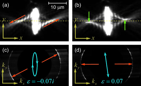
Remarkably, we observed extraordinary asymmetric deformations in the SPP beams when the input polarization of light was just slightly off from being parallel to the slit, as shown in Fig. 2. For instance, a tiny rotation of the quarter-wave plate (producing a slightly elliptical polarization) caused a strong angular deviation of the beams, whereas a tiny rotation of the half-wave plate (slightly tilted linear polarization) resulted in a well pronounced spatial displacement of the focal spot. These anomalous SPP beam shifts represent plasmonic SHEL and can be associated with “quantum weak measurements” AAV ; Duck ; Jozsa ; Nori of the incident light helicity via spin-orbit coupling induced by the light-to-SPP transformation at the slit. First, we interpret the results within a simple “quantum weak measurements” model of the SOI of light, and afterwards will give a complete wave description of the problem.
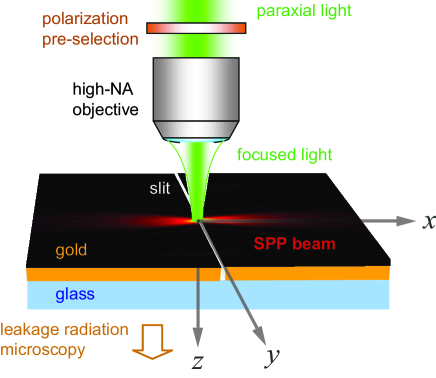
Let the incident light propagate along the -axis ( represents the gold surface), the slit be parallel to the -axis, whereas the SPP beams propagate in the directions (from now on we consider only the beam), Fig. 1. According to the “weak measurements” formalism, the external transverse spatial profile of the beam, , and its internal polarization state, , represent “classical measuring subsystem” and “quantum measured subsystem”, respectively Duck . For simplicity, let the -distribution of the incident light be Gaussian in the focal plane:
| (1) |
where is the beam waist and is the wavenumber of light. At the same time, using the basis of linear polarizations and along the corresponding axes, and the spin basis of right- and left-hand circular polarizations, and , the pre-selected input polarization of light is chosen to be almost -linear:
| (2) |
Here () is a complex number, with real and imaginary corresponding to the slightly tilted linear and slightly elliptical polarizations, respectively (see Fig. 2). In the spin basis, states and are the eigenvectors of the photon helicity operator Review .
Interaction of light with the slit and transformation to SPPs is similar to the beam refraction at a plane interface, and the geometric-phase difference between the constituent plane-wave components produce the SOI of light HK ; Review ; Remark I . One can show Plasmonic1 that the geometric-phase factor for the generated SPP waves with different -vectors is for (cf. HK ; Review ), which implies the dimensionless SOI Hamiltonian
| (3) |
where is the SHEL shift playing role of the coupling constant HK . Employing the weak-measurement interpretation HK ; Duck , the transverse profile of the beam, Gaussian-distributed in and “weakly measures” its helicity multiplied by the SHEL constant at the moment of interaction with the interface (slit).
Since the -component of the incident electric wave field cannot interact with plasmons via the slit, this naturally defines the post-selected polarization state to be perpendicular to the slit:
| (4) |
In fact, this state in the local coordinate frame attached to the direction of propagation of the beam corresponds to the -component of the SPP beam propagating along the -axis.
In terms of weak measurements, the input and output polarization states (2) and (4) determine the weak value of the photon helicity HK ; AAV ; Duck ; Jozsa ; Nori :
| (5) |
Remarkably, this weak value is complex and large, , although the photon helicity eigenvalues are . It is seen from Eq. (5) that elliptical and linear tilted pre-selected polarizations yield real and imaginary , respectively. Weak measurement of helicity, Eq. (5), results in the transverse shift of the “measuring subsystem”, i.e., of the transverse beam profile Duck :
| (6) |
Thus, the output SPP beam undergoes complex transverse shift (6) equaling to the SHEL shift multiplied by the helicity weak value (5). In this manner, real and imaginary parts of produce coordinate shift (displacement) and momentum shift (deflection) of the beam profile BB2 ; HK ; Aiello ; Qin ; Review ; Jozsa :
| (7) |
Note that the weak-measurement approximation fails in the vicinity of and is applicable at Duck .
Compare now the above weak-measurement model, based on the SOI of light, with the experimental plasmonic results presented in Fig. 2. Both coordinate and momentum shifts are clearly visible in the SPP fields in real (a,b) and Fourier (c,d) spaces for two types of the pre-selected polarization. However, the observed coordinate and momentum shifts of the SPP beams turn out to be swapped as compared to the model (5)–(7): Real (tilted linear polarization) causes coordinate shift , whereas imaginary (elliptical polarization) induces momentum shift . As we show below, the accurate description of the light-SPP coupling appends an additional phase factor that interchanges coordinate and momentum shifts with respect to the real or imaginary nature of . These swapped relations with respect to usual SHEL shifts have to be understood as an inherent feature of the plasmonic SHEL.
Complete wave theory.— The detailed wave picture of light evolution in the system can be divided into three stages: (i) focusing of the initial paraxial polarized field by a high-NA objective; (ii) interaction of the focused field with the slit; and (iii) generation and propagation of the SPP beams.
First, approximating the incident light by a single plane wave with the complex electric-field amplitude (in the Cartesian basis), the high-NA focusing is described by the Debye-Wolf approach Focusing2 ; RW . It implies that the transverse electric field of the wave is parallel-transported along each geometrical-optics ray, refracted by the lens, without change of the polarization state in the local coordinates. Marking the rays by spherical angles indicating the direction of the wave vectors , the plane-wave spectrum of the focused field, , is given by geometric rotational transformation Focusing2 :
| (8) |
Here , with denoting the SO(3) matrix operator of rotation about the -axis by the angle , and is the apodization factor which provides conservation of the energy flow RW . The real-space focused field is given by the Fourier-type integral over all plane waves , but the coupling with the SPPs is described in the momentum representation, and we perform this integration afterwards.
Second, the focused field (8) interacts with the slit. In doing so, only and components of the field can excite SPPs, whereas the component, parallel to the slit, does not take part in the interaction. In other words, the slit acts as a polarizer which cuts out the component of the field. This is described by the projection of the field onto the plane:
| (9) |
where is the projection operator.
Finally, the field can be considered as the source for the SPPs. Excited SPP field can be decomposed into plane waves which are characterized by the real wave vectors (dissipation is neglected hereafter), exponential decay away from the metal surface, at , and the complex electric-field amplitudes . From Maxwell equations it follows that the longitudinal and transverse field components are related as , Bradberry . Excitation of the SPPs by focused light via the slit is determined by: (i) the phase matching condition that provides transformation of the wave momenta and (ii) the coupling efficiency, , which we model by the inner product of the electric-field amplitudes of the incident light and SPPs: Remark II . Since the system is homogeneous in the -direction, the corresponding momentum component must be conserved. Taking into account that the SPP wave number is fixed (which determines the SPP circle in the Fourier space, Fig. 2), the phase matching condition can be written as
| (10) |
where . From here and equations above, the SPP plane-wave amplitude is
| (11) |
Taking into account the coupling efficiency , the resulting SPP field in the momentum and coordinate representations reads
| (12) |
Here the second Eq. (12) is the Fourier (Debye) integral over all incoming plane waves, is the aperture angle of the focusing objective, and we consider only the -distribution of the SPP field, omitting the common -dependence.
Equations (8)–(12) completely describe our system starting from the incident paraxial field and yielding the output SPP field distribution on the gold layer. We have verified numerically that these equations yield SPP distributions and shifts corresponding to experimental Figure 2 SOM .
In fact, for our experiment one can use the first post-paraxial approximation, and , which significantly simplifies equations and allows analytical solution. Keeping only terms linear in and , but neglecting -order terms, Eqs. (8)–(12) yield
| (13) |
where . This results in the following coupling coefficient and the SPP field:
| (14) |
It is seen from here that the imaginary longitudinal SPP field plays crucial role in the coupling with light. Indeed, the weak component of the input polarization, , is multiplied by because of the coupling between the -components of light and SPP fields. Therefore, imaginary transverse wave number of SPPs, , effectively swaps the real and imaginary parts of in the coupling process. Hence, in order to make the weak-measurement formalism (1)–(7) consistent with our plasmonic system, one has to substitute or in Eqs. (3)–(7). This modification immediately ascertains perfect agreement between the weak-measurement model and experimental results in Fig. 2.
To compare experiment and theory quantitatively, we calculate the SPP beam centroids in the coordinate and momentum spaces. Taking into account that the position operator is in the momentum representation, we define and , where the inner product implies the scalar product of the complex vector amplitudes and the integration in the momentum space: . Performing these calculations with the SPP Fourier spectrum (14), we finally arrive at
| (15) |
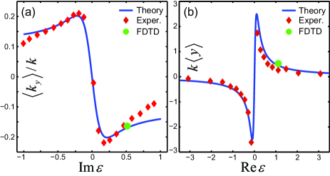
We emphasize that Eqs. (15) are valid in the whole range of values of . In the weak-measurement range , they are precisely equivalent to Eqs. (7) with modification , i.e., , and . Comparisons of the experimentally measured coordinate and momentum transverse shifts (as dependent on the complex polarization parameter ) with the theoretical results (15) are shown in Figure 3. Moreover, we performed a finite difference time domain (FDTD) simulations for two input polarizations, and the resulting shifts are also presented in Fig. 3. Evidently, the experiment, wave theory, weak-measurement interpretation, and FDTD simulations are all in perfect agreement SOM .
Conclusion.— We have observed and examined in detail an extraordinary plasmonic SHEL appearing in the interaction of focused light with a straight slit on the metal surface. Remarkably, this simple system offers a perfect weak-measurement tool where fixed polarization of SPPs provides a built-in post-selection. Tiny variations of the input polarization of light bring about huge SHEL shifts of the SPP beams in coordinate and momentum spaces, which correspond to the imaginary and real parts of the weak value of the helicity of light. The presented results demonstrate the unique ability of surface waves to perform as a post-selecting measuring device which might be potentially useful for various sensing applications involving the chirality of light.
We acknowledge fruitful discussions with Y. P. Bliokh and A. Y. Nikitin, and the financial support from the ERC (Grant 227577) and the European Commission (Marie Curie Action).
References
- (1) F. I. Fedorov, Dokl. Akad. Nauk SSSR 105, 465 (1955).
- (2) C. Imbert, Phys. Rev. D 5, 787 (1972).
- (3) H. Schilling, Ann. Phys. (Berlin) 16, 122 (1965); J. Ricard, Nouv. Rev. Opt. 5, 7 (1974); J. P. Hugonin and R. Petit, J. Opt. 8, 73 (1977).
- (4) M. A. Player, J. Phys. A: Math. Gen. 20, 3667 (1987); V. G. Fedoseyev, J. Phys. A: Math. Gen. 21, 2045 (1988).
- (5) L. Dutriaux, A. Le Floch, and F. Bretenaker, Europhys. Lett. 24, 345 (1993); F. Pillon, H. Gilles, and S. Girard, Appl. Opt. 43, 1863 (2004).
- (6) V. S. Liberman and B. Y. Zel’dovich, Phys. Rev. A 46, 5199 (1992).
- (7) K. Y. Bliokh and Y. P. Bliokh, Phys. Lett. A 333, 181 (2004); K. Y. Bliokh, A. Niv, V. Kleiner, and E. Hasman, Nature Photon. 2, 748 (2008).
- (8) M. Onoda, S. Murakami, and N. Nagaosa, Phys. Rev. Lett. 93, 083901 (2004).
- (9) K. Y. Bliokh and Y. P. Bliokh, Phys. Rev. Lett. 96, 073903 (2006).
- (10) K. Y. Bliokh and Y. P. Bliokh, Phys. Rev. E 75, 066609 (2007).
- (11) O. Hosten and P. Kwiat, Science 319, 787 (2008).
- (12) A. Aiello and J. P. Woerdman, Opt. Lett. 33, 1437 (2008); A. Aiello, M. Merano, and J. P. Woerdman, Phys. Rev. A 80, 061801(R) (2009); M. R. Dennis and J. B. Götte, arXiv:1204.0327v1.
- (13) Y. Qin, Y. Li, H. He, and Q. Gong, Opt. Lett. 34, 2551 (2009); Y. Qin, Y. Li, X. Feng, Y.-F. Xiao, H. Yang, and Q. Gong, Opt. Express 19, 9636 (2011).
- (14) K. Y. Bliokh, A. Aiello, and M. A. Alonso, in The Angular Momentum of Light, edited by D. L. Andrews and M. Babiker (Cambridge University Press, 2012, to appear).
- (15) Y. Aharonov, D. Z. Albert, and L. Vaidman, Phys. Rev. Lett. 60, 1351 (1988).
- (16) I. M. Duck, P. M. Stevenson, and E. C. G. Sudarshan, Phys. Rev. D 40, 2112 (1989).
- (17) R. Jozsa, Phys. Rev. A 76, 044103 (2007).
- (18) Y. Aharonov, S. Popescu, and J. Tollaksen, Physics Today 63, 27 (2010); A.G. Kofman, S. Ashhab, and F. Nori, arXiv:1109.6315; Y. Shikano, arXiv:1110.5055v3.
- (19) D. Haefner, S. Sukhov, and A. Dogariu, Phys. Rev. Lett. 102, 123903 (2009); Y. Zhao, J. S. Edgar, G. D. M. Jeffries, D. McGloin, and D. T. Chiu, Phys. Rev. Lett. 99, 073901 (2007).
- (20) O. G. Rodríguez-Herrera, D. Lara, K. Y. Bliokh, E. A. Ostrovskaya, and C. Dainty, Phys. Rev. Lett. 104, 253601 (2010); K. Y. Bliokh, E. A. Ostrovskaya, Miguel A. Alonso, O. G. Rodríguez-Herrera, D. Lara, and C. Dainty, Opt. Express 19, 26132 (2011).
- (21) K. Y. Bliokh, Y. Gorodetski, V. Kleiner, and E. Hasman, Phys. Rev. Lett. 101, 030404 (2008); Y. Gorodetski, A. Niv, V. Kleiner, and E. Hasman, Phys. Rev. Lett. 101, 043903 (2008).
- (22) N. Shitrit, I. Bretner, Y. Gorodetski, V. Kleiner, and E. Hasman, Nano Lett. 11, 2068 (2011).
- (23) W. L. Barnes, W. A. Murray, J. Dintinger, E. Devaux, and T.W. Ebbesen, Phys. Rev. Lett. 92, 107401 (2004).
- (24) A. Drezet, A. Hohenau, D. Koller, A. Stepanov, H. Ditlbacher, B. Steinberger, F. R. Aussenegg, A. Leitner, and J. R. KrennGordon, J. MSEB 149, 220 (2008).
- (25) High-NA focusing also induces SOI and partial spin-to-orbital angular momentum conversion in the incident light Focusing1 ; Focusing2 . However, efficiency of this conversion is estimated as here and can be neglected against the strong SOI () induced by the slit.
- (26) B. Richards and E. Wolf, Proc. Soc. London A 253, 358 (1959); P. Török, P. D. Higdon, and T. Wilson, Opt. Commun. 148, 300 (1998).
- (27) F. Yang, J. R. Sambles, and G. W. Bradberry, Phys. Rev. B 44, 5855 (1991).
- (28) This coupling coefficient implies equal efficiency of couplings for the and components of the fields. In general, this is not so because of the strong anisotropy of the system in the plane. The coupling anisotropy can be taken into account by modifying coefficient relating the longitudinal and transverse SPP fields. Therefore, we regard as a free parameter, which is chosen in Fig. 3 to fit the experimental data.
- (29) Details of the centroid calculations and measurements, as well as experimental, theoretical, and FDTD distributions of the SPP fields at different input polarizations are given in Supplementary Material.