∎
Tel.:+972-8-6461583
Fax: +972-8-6472949
44email: zoharmo@ee.bgu.ac.il 55institutetext: L. Faraone 66institutetext: School of Electrical, Electronic and Computer Engineering, The University of Western Australia, M018 35 Stirling Highway Crawley WA 6009, Australia
New resonant cavity-enhanced absorber structures for mid-infrared detector applications
Abstract
A new dielectric Fabry-Perot cavity was designed for a resonant enhancing optical absorption by a thin absorber layer embedded into the cavity. In this cavity, the front mirror is a subwavelength grating with % retroreflection. For a HgCdTe absorber in a matching cavity of the new type, the design is shown to meet the combined challenges of increasing the absorbing efficiency of the entire device up to % and reducing its size and overall complexity, compared to a conventional resonant cavity enhanced HgCdTe absorber, while maintaining a fairly good tolerance against the grating’s fabrication errors.
Keywords:
Optical resonant cavity Photodetectors HgCdTe Gratings1 Introduction
It is well known, that incorporating a photosensitive or an optically active layer into a Fabry-Perot (FP) cavity enhances the efficiency of detection by or emission from the layer, as a consequence of the multiple reflections that occur between the cavity’s mirrors. The enhancement is maximized if the round-trip phase, i.e. the phase difference between each succeeding reflection, satisfies the resonance condition
| (1) |
Here is a resonance wavelength and is the refractive index (RI) and length of the FP cavity, respectively, and are the reflection phase of the mirror that is further away from and adjacent to the illuminated side (hereafter referred to as the front and back mirror, respectively), and is an integer. Eq.(1) is thumb rule accurate regardless of the type of flat-surface mirror being employed, whether it consist of thin metallic films, or is e.g. a distributed Bragg reflector (DBR) that is a stack of quarter-wave pairs of high/low (HL) RI dielectric layers heavens ; knittl .
Optical communication, interconnection and information processing systems require high-efficiency photodetectors (PDs). In response to this demand, the field of resonant-cavity-enhanced (RCE) PDs has steadily maturated over past two decades unlu ; deen . For thermal PDs, the optical absorbance is an accurate measure of the efficiency, while for photodiodes and photo-conductors the key figure is the quantum efficiency . For initial design of the RCE PDs, the adoption of has a widespread use unlu ; deen since thus the analysis is framed into optics alone rather than being restricted to a specific PD technology. It appears unlu that for obtaining it is at least necessary to have % resonant reflectivity from the front mirror, which is problematic for a DBR of any practical thickness because of the tight material requirements for epitaxial growth. Thus, it is relevant to consider an alternative replacement for the DBR mirror by a thin dielectric micro-optical component which can be % reflective in a broad spectral band. A device that can exhibit such a reflection anomaly with a proper design havaus ; chang-a is a dielectric subwavelength grating structure.
This paper presents a theoretical study to incorporate a subwavelength grating as the front mirror in the FP cavity, for PD applications in the mid-wave infrared (MWIR) range. For a vertical-cavity surface-emitting laser, using an air-bridge subwavelength grating as a suspended top mirror, has been proposed before bissaillon ; kim . Only limited work on RCE PDs for operation in the MWIR range has been reported thus far. Currently this is an area of great interest due to the potential for obtaining the uncooled PDs.
2 Design considerations and simulation tools
We adopted [see Sec. 1], so RCE PDs with an absorber layer characterized by a complex RI, , were analyzed only optically. To compute the reflectance, transmittance and spectra of RCE PDs including a grating, we used the rigorous coupled wave analysis recast with an in-layer S-matrix propagation algorithm aushava1 . For DBR based PDs, a limiting case at zero grating groove width, which coincides with the impedance form knittl of transfer matrix method, was employed. The optical spectra were computed in the range .
We put emphasis on the two issues: (i) optimizing the peak at m and m, which are kept fixed, while fulfilling Eq.(1); (ii) seeking the designs with a high tolerance of the efficiency to errors in the grating fabrication. Interim design parameters serving as trial ones for computer aided optimization, will be obtained using the reflection phases [see Eq.(1)] of stand-alone mirrors unlu , which means the mirrors put on an infinite medium of the same material as the cavity’s material (CdTe in our designs) and irradiated from the substrate.
3 Conventional RCE PD structures
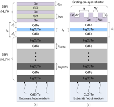
The reported RCE HgCdTe-PDs faraone1 ; faraone2 ; faraone3 have a standard configuration in which the CdTe FP cavity embeds a thin Hg0.71Cd0.29Te layer between two DBR mirrors [see in Fig.1(a)]. The HgCdTe/CdTe bilayers provide good lattice matching but the small difference in RIs of Hg0.56Cd0.44Te and CdTe requires , i.e. m thick DBR mirror, in order to achieve the desired reflectivity faraone3 . Apart from enlarging the cavity, the deposition of such a thick multilayer inevitably produces growth defects which deteriorate the reflectance. In practice, such DBRs have been fabricated with kanev and faraone3 and optimized with for high temperature-operation RCE PDs sioma .
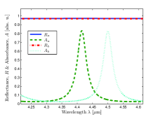
We adopted a mid value of , while due to faraone1 ; faraone2 ; faraone3 , . For a standard placement of the absorbing layer in the middle of the cavity (), combining semianalytical calculation and manual optimization, we found the optimal cavity length for which at [RCE-S structure in Table 2]. The automatic optimization results in the same as obtained manually. Further optimization, allowing for , yields RCE-Oa and RCE-Ob structures with and , respectively [see in Fig.3 and Table 2]. Figure 3 shows the spectra of the designed structures along with the reflectance () from the stand-alone front DBR mirror.
| Wavelengths | Ge | SiO | CdTe | Hg0.71Cd0.29Te | Hg0.56Cd0.44Te | CdZeTe |
|---|---|---|---|---|---|---|
| 2.6896 | ||||||
| 2.6895 |
4 Grating mirror based RCE PD structures
Figure 1(b) presents a modified RCE HgCdTe-PD, in which the front mirror is replaced by a one-dimensional (1-D) dielectric grating with period , groove width and depth , while the absorber, back mirror and irradiation scheme remain the same as those of the structure in Sec. 3. The grating is designed as the stand-alone % reflectivity mirror. Our design of the RCE absorber as a whole is done for the backside irradiation from CdZnTe substrate and is not suitable for the front irradiation from air [see Fig.1], because the grating mirror breaks down the irradiation symmetry inherent to the DBR based FP cavities.
4.1 Polarization-selective RCE HgCdTe-absorber structures
Earlier work havaus and a recent paper chang-a on designing grating mirrors have considered optical incidence from air, but here the stand-alone grating mirror is irradiated from CdTe. To get rid of the grating reflection orders, we imposed over all the computed wavelength range the subwavelength grating restriction , which is tighter than for the incidence from air. Because of polarization sensitivity of the 1-D gratings, we first maximized the for the incidence from CdTe half-space, separately for the TE and TM polarization.
Other trial dimensions were estimated semianalytically using the and as computed numerically for the stand-alone grating and DBR, respectively, and then refined by the optimization. The manual design was performed under the constraints: , and , by controlling the which allowed us to attain the desired . To remind, the optimization goal is to achieve maximal polarized , minimal changes of which due to variations in the grating fabrication process are being very desirable. A fully computer-aided optimization procedure easily allows for designing the structures with and . The results of such an optimization are the structures RCE-TEa and RCE-TMa (m), RCE-TEb and RCE-TMb (m) for operation with a TE and TM polarized radiation [see Table 2].
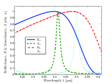
The TE and TM polarized spectra from the stand-alone grating mirrors and the related spectra of the RCE-TEa and RCE-TEb structures are shown in Fig. 3 and 5, respectively. The designed gratings maintain the polarized in a wide band around . For the TM polarization, as seen in Fig. 5, the high- band width greatly exceeds m, in a good agreement with the paper chang-a . For the TE polarization, however, this band is narrower which does not prevent from achieving the % peak [see Fig. 3] and a superior tolerance to a variation in the grating fabrication process, as discussed in Subsect. 4.2 below.
4.2 Design tolerances
An important issue for the practicality of the proposed RCE HgCdTe-PDs is the sensitivity to variations in the grating fabrication process. In this paper, we report the tolerance of the value and position of the peak to the grating groove duty cycle variations. The tolerance was found to be very good for the structures with the optimal , especially in the TE case. For example, the RCE-TEa structure still maintains high values of % and % with the initially prescribed and and , respectively. The small drop in , should not be treated as a deterioration of the detection performance since the peak % appears to be shifted by at most 3 nm from the , which indicates an excellent tolerance including a small change of the peak value and a minute shift of the peak position. The RCE-TEb structure exhibits similar tolerance properties.
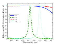
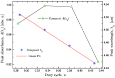
The RCE-TMa,b structures withstand errors in of as related to peak , which indicates a lower but still practical tolerance. However, the peak wavelength shift proves notably larger as compared to RCE-TEa,b structures. For example, as is shifted to the RCE-TMa structure exhibits a nm red shift of the absorption peak and a drop of the peak to . In this case, we found numerically that the peak wavelength, within a reasonable range, depends on linearly, as shown in Fig. 5.
5 Conclusion
The RCE HgCdTe-PDs, including new ones in which the front mirror is a reflectance grating, for applications in MWIR range, were designed and simulated using semianalytic and computer-aided tools such as a scrutinized control of the resonant round-trip phase , and the grating reflection amplitude and phase. The results show that the control is crucial for optimizing the efficiency, as was known for the conventional RCE PDs unlu ; faraone1 ; faraone2 ; faraone3 . In our case, and differ significantly, but the reflections from the absorbing layer have a relatively small effect due to . We also proved that a non-standard placement of the absorbing layer is capable of increasing the efficiency of the conventional RCE HgCdTe-PDs, which still remains below %.
It was decisively shown that for a linearly polarized light, the grating mirror based RCE HgCdTe-PDs can be designed to achieve efficiency, thus highly outperforming the conventional RCE HgCdTe-PDs, and simultaneously is highly tolerant to variations in the grating groove duty cycle . For the TM designs, a linear dependence was found between the varied around its optimal value and the peak wavelength shifting, in a response, around the prescribed .
| Structures | Peak | ||||||||
|---|---|---|---|---|---|---|---|---|---|
| RCE-S | 1.177 | 0.075 | 1.177 | - | - | - | - | 0.819 | - |
| RCE-Oa | 0.272 | 0.075 | 0.433 | - | - | - | - | 0.831 | - |
| RCE-Ob | 0.292 | 0.075 | 0.429 | - | - | - | - | 0.828 | - |
| RCE-TEa | 0.209 | 0.075 | 0.535 | 0.331 | 0.844 | 1.461 | 0.628 | 0.998 | 3.901 |
| RCE-TEb | 0.228 | 0.075 | 0.534 | 0.335 | 0.861 | 1.492 | 0.629 | 0.999 | 3.984 |
| RCE-TMa | 0.259 | 0.075 | 0.504 | 0.628 | 0.921 | 1.456 | 0.337 | 0.999 | 3.888 |
| RCE-TMb | 0.286 | 0.075 | 0.495 | 0.650 | 0.930 | 1.468 | 0.334 | 0.999 | 3.920 |
References
- (1) Heavens O. S.: Optical Properties of Thin Solid Films, Dover Publ., New York (1991).
- (2) Knittl Z.: Optics of Thin Films (an Optical Multilayer Theory, Wiley, New York (1976).
- (3) Ünlü M. S. and Strite S.: Resonant cavity enhanced photonic devices, J. Appl. Phys., 78, 607-639 (1995).
- (4) El-Batawy Y. M. and Deen M. J.: Resonant cavity enhanced photodetectors (RCE-PDs): structure, material analysis and optimization, Proc. SPIE, 4999, 363-378 (2003).
- (5) S. Hava and M. Auslender, Silicon grating-based mirror for 1.3-m polarized beams: MATLAB-aided design, Appl. Opt., 34, 1053-1058 (1995).
- (6) C. F. R. Mateus, M. C. Y. Huang, Y. Deng, A. R. Neureuther, and C. J. Chang-Hasnain, Ultrabroadband mirror using low-index cladded subwavelength grating, IEEE Photonics Technol. Lett., 16, 518-520 (2004).
- (7) E. Bissaillon, D. Tan, B. Faraji, A. G. Kirk, L. Chrostowski, and D. V. Plant, “High reflectivity air-bridge subwavelength grating reflector and Fabry-Perot cavity in AlGaAs/GaAs, Opt. Express, 14, 2573-2582 (2006).
- (8) J. H. Kim, L. Chrostowski, E. Bisaillon, and D. V. Plant DBR, subwavelength grating, and photonic crystal slab Fabry-Perot cavity design using phase analysis by FDTD, Opt. Express, 15, 10330-10339 (2007).
- (9) M. Auslender and S. Hava, Scattering-matrix propagation algorithm in full-vectorial optics of multilayer grating structures, Opt. Lett., 21, 1765-1767 (1996).
- (10) J. G. A. Wehner, C. A. Musca, R. H. Sewell, J. M. Dell, and L. Faraone, Mercury cadmium telluride resonant-cavity-enhanced photoconductive infrared detectors, Appl. Phys. Lett., 87, 211104:1-3 (2005).
- (11) J. G. A. Wehner, C. A. Musca, R. H. Sewell, J. M. Dell, and L. Faraone, Responsivity and lifetime of resonant-cavity-enhanced HgCdTe detectors, Solid-State Electron., 50, 1640-1648 (2006).
- (12) J. G. A. Wehner, R. H. Sewell, J. Antoszewski, C. A. Musca, J. M. Dell, and L. Faraone, Mercury cadmium telluride/cadmium telluride distributed Bragg reflectors for use with resonant cavity-enhanced detectors, J. Electron. Mater., 34, 710-715 (2005).
- (13) J. Kaniewski, J. Muszalski and J. Piotrowski, Resonant microcavity enhanced infrared photodetectors, Optica Applicata, 17, 405-413 (2007).
- (14) M. Sioma and J. Piotrowski, Modelling and optimisation of high temperature detectors of long wavelength infrared radiation with optically resonant cavity, Opto-Electron. Rev. 12, 157-160 (2004).